Page is loading ...

Manual No.
FS-OM2-0
4-12 in. FrostSafe™ Two-Way Damper
Operation, Maintenance and
Installation Manual
INTRODUCTION.....................................1
RECEIVING AND STORAGE.................1
DESCRIPTION OF OPERATION ...........1
INSTALLATION.......................................1
CONSTRUCTION...................................2
MAINTENANCE......................................2
TROUBLESHOOTING............................2
DISASSEMBLY.......................................2
REASSEMBLY........................................2
PARTS AND SERVICE...........................3
WARRANTY............................................3
® VAL-MATIC® VALVE AND MANUFACTURING CORP.
905 RIVERSIDE DR. ELMHURST, IL. 60126
TEL. 630 / 941-7600 FAX. 630 / 941-8042

1
4-12 in. FrostSafe™ Two-Way Damper
OPERATION, MAINTENANCE AND INSTALLATION
INTRODUCTION
This manual will provide you with the information to
properly install, maintain and ensure a long service
life for the FrostSafe™. The FrostSafe™ is installed
in vent pipes used to vent vaults, reservoirs and air
valves to help protect vault components and air
valves from freezing due to convection by minimizing
the flow of cold air into the vault while allowing air
flow in both directions when necessary. The
FrostSafe™ is designed with three flexible
membranes that fully open when venting and snap
closed when finished to prevent cold air from
entering.
RECEIVING AND STORAGE
Inspect the FrostSafe™ upon receipt for damage in
shipment. Unload all devices carefully to the ground
without dropping.
The devices should remain boxed, clean and dry
until installed to prevent weather related damage.
For long-term storage greater than six months, the
rubber membrane should be coated with a thin film
of FDA approved grease such as Lubriko #CW-606.
Do not expose rubber membrane to sunlight or
ozone for any extended period.
DESCRIPTION OF OPERATION
The FrostSafe™ is a wafer-style hingeless 2-way
damper that prevents cold air from entering the
vault, reservoir or air valve while still allowing the
vent to perform its function of admitting and
expelling air under normal operating conditions.
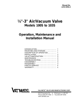
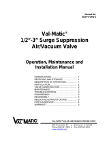
INSTALLATION
The installation of the FrostSafe™ is important for its
proper operation. The FrostSafe™ can be installed
in the vertical or horizontal position between typical
ANSI Class 125 flanges using standard connection
practices. The FrostSafe™ Device can be located in
the vault or above ground as shown in Figure 2.
The device can also be placed in series at both
locations for added protection. Since the
FrostSafe™ is a two-way flow device, it has no
designated flow direction.
Flanged connections should only be mated with flat-
faced pipe flanges. The bolts should be tightened in
gradual steps using the crossover method.
Recommended torque values are given in Table 1.
The FrostSafe™ can be used with rubber or
compressed fiber ring-type gaskets.
TABLE 1. FLANGE BOLT TORQUES
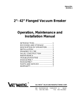
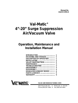
Figure 1. FrostSafe™ Two-Way Damper
Mounting Flange Bolts
Device
Size Bolt
Size Recommended
Torque (ft-lbs) Maximum
Torque (ft-lbs)
4 5/8” 20 30
8 3/4” 30 40
12 7/8" 60 70
CAUTION: The use of excessive bolt torque
may damage the device.

2
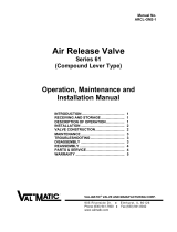
ITEM DESCRIPTION MATERIAL
1 Body HDPE
2 Rubber Membrane High Grade Neoprene
3 Damper Seal PETG
4 Body Bolt T316 Stainless Steel
WARNING: If the FrostSafe™ is installed
downstream of an air valve, the
air valve’s isolation valve must be
closed prior to performing
inspection or maintenance of the
FrostSafe™. Failure to close the
isolation valve could lead to
bodily injury if the air valve
discharges air during inspection.
Figure 2. Typical Installation
FROSTSAFE™ CONSTRUCTION
The standard FrostSafe™ is constructed of quality
corrosion resistant materials including high density
polyethylene (HDPE) and Stainless steel type 316
bolts. The general details of construction are
illustrated in Figure 3 and identified in Table 2.
Figure 3: FrostSafe™ Cross Section of
Components
Table 2: FrostSafe™ Parts List
MAINTENANCE
The FrostSafe™ requires no scheduled lubrication
or maintenance.
INSPECTION: The FrostSafe™ may be checked for
debris by following the disassembly and reassembly
instructions. The body may be checked for cracks
and gouges and the damper seal for tears. The
rubber membranes may be inspected for aging,
tears or deep scratches.
TROUBLESHOOTING
Troubleshooting is presented below to assist you
with the FrostSafe™ in an efficient manner.
• FrostSafe™ Stuck Open: Clean and inspect the
damper seal and rubber membranes for debris.
DISASSEMBLY
1. Loosen the pipe flange bolts, separate the flanges
and remove the FrostSafe™.
2. Use an Allen wrench to remove the button head
cap screws (4).
3. Pull the body halves apart to inspect the damper
seal (3) and the rubber membranes (2).
REASSEMBLY
All parts must be clean. Worn or damaged parts
should be replaced during reassembly.
1. Insert screws into counterbores of one of the
damper bodies (1).
2. Place one of the rubber membranes (2) into the
register making sure to put the screw through one
of the bolt holes cut into the membrane.
3. Lay the plastic damper seal (3) on top of the
rubber membrane (2) making sure to align the cut
patterns for proper mating.
4. Place the other rubber membrane (2) on top of
the damper seal completing the three-layer
structure. Again, make sure to align the cut
patterns for proper mating.

3
LIMITED WARRANTY
All products are warranted to be free of defects in material and workmanship for a period of one year from the date of
shipment, subject to the limitations below.
If the purchaser believes a product is defective, the purchaser shall: (a) Notify the manufacturer, state the alleged defect and reques
t
permission to return the product; (b) if permission is given, return the product with transportation prepaid. If the product is accepted
for return and found to be defective, the manufacturer will, at his discretion, either repair or replace the product, f.o.b. factory, within
60 days of receipt, or refund the purchase price. Other than to repair, replace or refund as described above, purchaser agrees that
manufacturer shall not be liable for any loss, costs, expenses or damages of any kind arising out of the product, its use, installation
or replacement, labeling, instructions, information or technical data of any kind, description of product use, sample or model,
warnings or lack of any of the foregoing. NO OTHER WARRANTIES, WRITTEN OR ORAL, EXPRESS OR IMPLIED, INCLUDING THE
WARRANTIES OF FITNESS FOR A PARTICULAR PURPOSE AND MERCHANTABILITY, ARE MADE OR AUTHORIZED. NO
AFFIRMATION OF FACT, PROMISE, DESCRIPTION OF PRODUCT OF USE OR SAMPLE OR MODEL SHALL CREATE ANY WARRANT
Y
FROM MANUFACTURER, UNLESS SIGNED BY THE PRESIDENT OF THE MANUFACTURER. These products are not manufactured,
sold or intended for personal, family or household purposes.
5. Align the threaded holes of the other damper body
with the protruding screws. Use an Allen wrench
to install the screws taking care not to strip the
threads in the body (DO NOT USE AN IMPACT
GUN). A gap between the two body halves is
acceptable.
PARTS AND SERVICE
Parts and service are available from your local
representative or the factory. Make note of the
Valve Size and Model Number located on the valve
nameplate and contact:
Val-Matic Valve and Manufacturing Corp.
905 Riverside Drive
Elmhurst, IL 60126
Phone: (630) 941-7600
Fax: (630) 941-8042
www.valmatic.com
A sales representative will quote prices for parts or
arrange for service as needed.
® VAL-MATIC® VALVE AND MANUFACTURING CORP.
905 RIVERSIDE DR. ELMHURST, IL. 60126
TEL. 630 / 941-7600 FAX. 630 / 941-8042
/