Page is loading ...

Page 1 of 4
Installation and Operation Instructions
2020 PIU C3100/C3900 SPEAKER
IMPORTANT! Read all instructions before installing and using. Installer: This manual must be delivered to the end user.
WARNING!
Failure to install or use this product according to manufacturer’s recommendations may result in property damage, serious injury, and/
or death to those you are seeking to protect!
Do not install and/or operate this safety product unless you have read and understood the safety information
contained in this manual.
1. Proper installation combined with operator training in the use, care, and maintenance of emergency warning devices are essential to
ensure the safety of emergency personnel and the public.
2. Emergency warning devices often require high electrical voltages and/or currents. Exercise caution when working with live electrical
connections.
3. This product must be properly grounded. Inadequate grounding and/or shorting of electrical connections can cause high current arcing,
which can cause personal injury and/or severe vehicle damage, including re.
4. Proper placement and installation is vital to the performance of this warning device. Install this product so that output performance of
the system is maximized and the controls are placed within convenient reach of the operator so that they can operate the system without
losing eye contact with the roadway.
5. Do not install this product or route any wires in the deployment area of an air bag. Equipment mounted or located in an air bag
deployment area may reduce the eectiveness of the air bag or become a projectile that could cause serious personal injury or death.
Refer to the vehicle owner’s manual for the air bag deployment area. It is the responsibility of the user/operator to determine a suitable
mounting location ensuring the safety of all passengers inside the vehicle particularly avoiding areas of potential head impact.
6. It is the responsibility of the vehicle operator to ensure daily that all features of this product work correctly. In use, the vehicle operator
should ensure the projection of the warning signal is not blocked by vehicle components (i.e., open trunks or compartment doors),
people, vehicles or other obstructions.
7. The use of this or any other warning device does not ensure all drivers can or will observe or react to an emergency warning signal.
Never take the right-of-way for granted. It is the vehicle operator’s responsibility to be sure they can proceed safely before entering an
intersection, drive against trac, respond at a high rate of speed, or walk on or around trac lanes.
8. This equipment is intended for use by authorized personnel only. The user is responsible for understanding and obeying all laws
regarding emergency warning devices. Therefore, the user should check all applicable city, state, and federal laws and regulations. The
manufacturer assumes no liability for any loss resulting from the use of this warning device.

Page 2 of 4
Step 1. Consult the factory service manual to remove the front bumper cover from the vehicle.
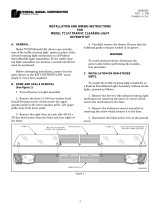
Step 2. Test t the bracket into position as shown in Figure 3. The bracket is positioned behind the center brace. Slight drilling/reaming of the
holes in the brace may be required for the mounting screws provided in this kit.
Step 3. Mount the desired speaker (C3100/C3900) to the desired bracket using the supplied fasteners as shown in Figure 1. C3100 with the
(4) four supplied screws, C3900 with the (2) two supplied screws.
Step 4. Position the bracket behind the central support as shown in Figure 2.
Step 5. Mount the bracket into position using (4) supplied 1/4-20 fasteners in positions as indicated in Figure 3.
Step 6. (For Dual Speaker Applications) - Repeat process using the opposite side speaker bracket, mirroring the position on the central
brace.
Figure 1
Installation and Mounting:
Figure 2
Figure 3

Page 3 of 4
Notes:

Page 4 of 4
Product Returns:
If a product must be returned for repair or replacement*, please contact our factory to obtain a Return Goods Authorization Number (RGA
number) before you ship the product to Code 3®, Inc. Write the RGA number clearly on the package near the mailing label. Be sure you use
sucient packing materials to avoid damage to the product being returned while in transit.
*Code 3®, Inc. reserves the right to repair or replace at its discretion. Code 3®, Inc. assumes no responsibility or liability for expenses incurred for the removal and /or reinstallation of products requiring
service and/or repair.; nor for the packaging, handling, and shipping: nor for the handling of products returned to sender after the service has been rendered.
Manufacturer Limited Warranty Policy:
Manufacturer warrants that on the date of purchase this product will conform to Manufacturer’s specications for this product (which are avail-
able from the Manufacturer upon request). This Limited Warranty extends for Sixty (60) months from the date of purchase.
DAMAGE TO PARTS OR PRODUCTS RESULTING FROM TAMPERING, ACCIDENT, ABUSE, MISUSE, NEGLIGENCE, UNAPPROVED MODIFICA-
TIONS, FIRE OR OTHER HAZARD; IMPROPER INSTALLATION OR OPERATION; OR NOT BEING MAINTAINED IN ACCORDANCE WITH THE
MAINTENANCE PROCEDURES SET FORTH IN MANUFACTURER’S INSTALLATION AND OPERATING INSTRUCTIONS VOIDS THIS LIMITED WAR-
RANTY.
Exclusion of Other Warranties:
MANUFACTURER MAKES NO OTHER WARRANTIES, EXPRESS OR IMPLIED. THE IMPLIED WARRANTIES FOR MERCHANTABILITY, QUALITY
OR FITNESS FOR A PARTICULAR PURPOSE, OR ARISING FROM A COURSE OF DEALING, USAGE OR TRADE PRACTICE ARE HEREBY EX-
CLUDED AND SHALL NOT APPLY TO THE PRODUCT AND ARE HEREBY DISCLAIMED, EXCEPT TO THE EXTENT PROHIBITED BY APPLICABLE
LAW. ORAL STATEMENTS OR REPRESENTATIONS ABOUT THE PRODUCT DO NOT CONSTITUTE WARRANTIES.
Remedies and Limitation of Liability:
MANUFACTURER’S SOLE LIABILITY AND BUYER’S EXCLUSIVE REMEDY IN CONTRACT, TORT (INCLUDING NEGLIGENCE), OR UNDER ANY
OTHER THEORY AGAINST MANUFACTURER REGARDING THE PRODUCT AND ITS USE SHALL BE, AT MANUFACTURER’S DISCRETION, THE
REPLACEMENT OR REPAIR OF THE PRODUCT, OR THE REFUND OF THE PURCHASE PRICE PAID BY BUYER FOR NON-CONFORMING PROD-
UCT. IN NO EVENT SHALL MANUFACTURER’S LIABILITY ARISING OUT OF THIS LIMITED WARRANTY OR ANY OTHER CLAIM RELATED TO
THE MANUFACTURER’S PRODUCTS EXCEED THE AMOUNT PAID FOR THE PRODUCT BY BUYER AT THE TIME OF THE ORIGINAL PURCHASE.
IN NO EVENT SHALL MANUFACTURER BE LIABLE FOR LOST PROFITS, THE COST OF SUBSTITUTE EQUIPMENT OR LABOR, PROPERTY
DAMAGE, OR OTHER SPECIAL, CONSEQUENTIAL, OR INCIDENTAL DAMAGES BASED UPON ANY CLAIM FOR BREACH OF CONTRACT, IM-
PROPER INSTALLATION, NEGLIGENCE, OR OTHER CLAIM, EVEN IF MANUFACTURER OR A MANUFACTURER’S REPRESENTATIVE HAS BEEN
ADVISED OF THE POSSIBILITY OF SUCH DAMAGES. MANUFACTURER SHALL HAVE NO FURTHER OBLIGATION OR LIABILITY WITH RESPECT
TO THE PRODUCT OR ITS SALE, OPERATION AND USE, AND MANUFACTURER NEITHER ASSUMES NOR AUTHORIZES THE ASSUMPTION OF
ANY OTHER OBLIGATION OR LIABILITY IN CONNECTION WITH SUCH PRODUCT.
This Limited Warranty denes specic legal rights. You may have other legal rights which vary from jurisdiction to jurisdiction. Some jurisdic-
tions do not allow the exclusion or limitation of incidental or consequential damages.
© 2019 Code 3, Inc. all rights reserved.
920-0774-00 Rev. B
Warranty:
10986 North Warson Road
St. Louis, MO 63114
Technical Service
USA (314) 996-2800
Customer Service
UK +44 (0)113 237 5340
AUS +61 (0)3 63322444
www.code3esg.com
An ECCO SAFETY GROUP™ Brand
www.eccosafetygroup.com

920-0633-00 Rev. A Page 1 of 4
Introduction:
This C3100 Speaker Mounting Bracket kit ts 2015+ PI
Utility & mounts the Code3 C3100 speaker either singly
or in pairs side by side.
IMPORTANT! Read all instructions before installing and using. Installer: This manual must be delivered to the end user.
WARNING!
Failure to install or use this product according to manufacturers recommendations may result in property damage, serious injury,
and/or death to those you are seeking to protect!
1. Proper installation combined with operator training in the use, care, and maintenance of emergency warning devices are essential to
ensure the safety of emergency personnel and the public.
2. Emergency warning devices often require high electrical voltages and/or currents. Exercise caution when working with live electrical
connections.
3. This product must be properly grounded. Inadequate grounding and/or shorting of electrical connections can cause high current arcing,
which can cause personal injury and/or severe vehicle damage, including re.
4. Proper placement and installation is vital to the performance of this warning device. Install this product so that output performance of the
system is maximized and the controls are placed within convenient reach of the operator so that s/he can operate the system without losing
eye contact with the roadway.
5. It is the responsibility of the vehicle operator to ensure daily that all features of this product work correctly. In use, the vehicle operator
should ensure the projection of the warning signal is not blocked by vehicle components (i.e., open trunks or compartment doors), people,
vehicles or other obstructions.
6. The use of this or any other warning device does not ensure all drivers can or will observe or react to an emergency warning signal. Never
take the right-of-way for granted. It is your responsibility to be sure you can proceed safely before entering an intersection, drive against
trafc, respond at a high rate of speed, or walk on or around trafc lanes.
7. This equipment is intended for use by authorized personnel only. The user is responsible for understanding and obeying all laws regarding
emergency warning devices. Therefore, the user should check all applicable city, state, and federal laws and regulations. The manufacturer
assumes no liability for any loss resulting from the use of this warning device.
Do not install and/or operate this safety product unless you have read and understand the safety information con-
tained in this manual.
WARNING!
Sirens product lous sounds that may damage hearing
• Wear hearing protection when testing
• Use siren only for emergency response
• Roll up windows when siren is operating
• Avoid exposure to the siren sound outside of vehicle
Installation and Operation Instructions
C3100 SPEAKER MOUNT - 2015+ PI UTILITY
FOR SINGLE AND DUAL SPEAKERS
DUAL SPEAKER MOUNT SHOWN
Contents:
Specications.........................................................01
Installation and Mounting..................................02-03
Warranty.................................................................04
Specications:
The C3100 Speaker Mounting bracket kit ts 2015+ PI Utility
and mounts the Code3 C3100 speaker either singly or in
pairs side by side. The bracket dimensions are 14.00” Wide X
11.375 High X 1.10” Deep.
For C3100 speaker specications, wiring & operation, see the
Code3 C3100 installation manual.

920-0633-00 Rev. A Page 2 of 4
Installation and Mounting:
Step 1. For a single speaker application, assemble the C3100 speaker to the mounting bracket as shown in gure 1. For a dual
speaker application, assemble the C3100 speaker to the mounting plate as shown in gure 2. Use (4) of the #12 phillips head screws
and star lock washers that are supplied in the #55025 hardware bags to mount each of the C3100 speakers. Make sure the “MOUNT
WITH THIS END UP” “CAUTION!” label is on the top as oriented in the views in Figures 1, 2 & 3 below. Discard the remaining hard-
ware.
Step 2. Refer to the Ford Service manual for steps required to remove the front facia from the PI Utility.
Step 3. Note the (2) existing holes that are 12 1/4 inches apart in the PI Utility’s front bumper brace (See Figure 3 Front View below).
Position the speaker assembly with the speakers facing forward on the vehicle and slip the mounting ange up behind the PI Utility’s
bumper brace (The back side of the brace is at while the front side is curved to match the curvature of the front facia). Align the (2)
holes in the speaker bracket mounting ange with the holes in the PI Utility’s bumper brace and slip the (2) provided 5/16”-18 X 3”
long stainless steel bolts from the back side through the holes in the bracket and through the holes in the vehicle’s bumper brace. slip
a provided 5/16 I.D. X 1 1/4” O.D. fender washer over the threads of the bolts and thread a provided 5/16” hex locking nut onto each
of the bolts. See Figure 4 on page 3 for a cross section view of the assembly.
Step 3. Have an assistant hold the speakers up or prop something under the speakers so they are positioned up under the PI Utility’s
bumper brace and tighten the nuts until they are snugged up and the speakers are up close to the bottom of the bumper brace (about
1/8” to 1/4” Gap).
Step 4. Route the wiring as desired to connect the speakers to the siren.
Figure 1 Single Speaker Version Figure 2 Dual Speaker Version
12 1/4"
PI UTILITY'S
FRONT BUMPER
BRACE
C3100 SPEAKERS
(DUAL VERSION SHOWN)
HOLE LOCATIONS IN PI UTILITY'S
FRONT BUMPER BRACE
Figure 3 Front View

920-0633-00 Rev. A Page 3 of 4
C3100 SPEAKER
MOUNT BRACKET
5/16"-18 X 3" BOLT
PI UTILITY'S FRONT
BUMPER BRACE
5/16"-18 HEX
LOCKING NUT
5/16" X 1 1/4" O.D.
FENDER WASHER
C3100 SPEAKER
TO FRONT
OF VEHICLE
Figure 4 Cross Sectional View

920-0633-00 Rev. A Page 4 of 4
Manufacturer Limited Warranty Policy:
Manufacturer warrants that on the date of purchase this product will conform to Manufacturer’s specications for this product (which are avail-
able from the Manufacturer upon request). This Limited Warranty extends for Sixty (60) months from the date of purchase.
DAMAGE TO PARTS OR PRODUCTS RESULTING FROM TAMPERING, ACCIDENT, ABUSE, MISUSE, NEGLIGENCE, UNAPPROVED MODIFICA-
TIONS, FIRE OR OTHER HAZARD; IMPROPER INSTALLATION OR OPERATION; OR NOT BEING MAINTAINED IN ACCORDANCE WITH THE
MAINTENANCE PROCEDURES SET FORTH IN MANUFACTURER’S INSTALLATION AND OPERATING INSTRUCTIONS VOIDS THIS LIMITED WAR-
RANTY.
Exclusion of Other Warranties:
MANUFACTURER MAKES NO OTHER WARRANTIES, EXPRESS OR IMPLIED. THE IMPLIED WARRANTIES FOR MERCHANTABILITY, QUALITY
OR FITNESS FOR A PARTICULAR PURPOSE, OR ARISING FROM A COURSE OF DEALING, USAGE OR TRADE PRACTICE ARE HEREBY EX-
CLUDED AND SHALL NOT APPLY TO THE PRODUCT AND ARE HEREBY DISCLAIMED, EXCEPT TO THE EXTENT PROHIBITED BY APPLICABLE
LAW. ORAL STATEMENTS OR REPRESENTATIONS ABOUT THE PRODUCT DO NOT CONSTITUTE WARRANTIES.
Remedies and Limitation of Liability:
MANUFACTURER’S SOLE LIABILITY AND BUYER’S EXCLUSIVE REMEDY IN CONTRACT, TORT (INCLUDING NEGLIGENCE), OR UNDER ANY
OTHER THEORY AGAINST MANUFACTURER REGARDING THE PRODUCT AND ITS USE SHALL BE, AT MANUFACTURER’S DISCRETION, THE
REPLACEMENT OR REPAIR OF THE PRODUCT, OR THE REFUND OF THE PURCHASE PRICE PAID BY BUYER FOR NON-CONFORMING PROD-
UCT. IN NO EVENT SHALL MANUFACTURER’S LIABILITY ARISING OUT OF THIS LIMITED WARRANTY OR ANY OTHER CLAIM RELATED TO
THE MANUFACTURER’S PRODUCTS EXCEED THE AMOUNT PAID FOR THE PRODUCT BY BUYER AT THE TIME OF THE ORIGINAL PURCHASE.
IN NO EVENT SHALL MANUFACTURER BE LIABLE FOR LOST PROFITS, THE COST OF SUBSTITUTE EQUIPMENT OR LABOR, PROPERTY
DAMAGE, OR OTHER SPECIAL, CONSEQUENTIAL, OR INCIDENTAL DAMAGES BASED UPON ANY CLAIM FOR BREACH OF CONTRACT, IM-
PROPER INSTALLATION, NEGLIGENCE, OR OTHER CLAIM, EVEN IF MANUFACTURER OR A MANUFACTURER’S REPRESENTATIVE HAS BEEN
ADVISED OF THE POSSIBILITY OF SUCH DAMAGES. MANUFACTURER SHALL HAVE NO FURTHER OBLIGATION OR LIABILITY WITH RESPECT
TO THE PRODUCT OR ITS SALE, OPERATION AND USE, AND MANUFACTURER NEITHER ASSUMES NOR AUTHORIZES THE ASSUMPTION OF
ANY OTHER OBLIGATION OR LIABILITY IN CONNECTION WITH SUCH PRODUCT.
This Limited Warranty denes specic legal rights. You may have other legal rights which vary from jurisdiction to jurisdiction. Some jurisdic-
tions do not allow the exclusion or limitation of incidental or consequential damages.
Product Returns:
If a product must be returned for repair or replacement*, please contact our factory to obtain a Return Goods Authorization Number (RGA number)
before you ship the product to Code 3®, Inc. Write the RGA number clearly on the package near the mailing label. Be sure you use sufcient
packing materials to avoid damage to the product being returned while in transit.
*Code 3®, Inc. reserves the right to repair or replace at its discretion. Code 3®, Inc. assumes no responsibility or liability for expenses incurred for the removal and /or reinstallation of products requiring service and/or repair.; nor for the packaging, handling,
and shipping: nor for the handling of products returned to sender after the service has been rendered.
10986 North Warson Road
St. Louis, MO 63114
Technical Service
(314) 996-2800
www.code3esg.com
An ECCO SAFETY GROUP™ Company
www.eccosafetygroup.com

1
INSTALLATION &
OPERATION
MANUAL
Read all instructions and warnings before installing and using.
This manual must be delivered to the end user of this equipment.
IMPORTANT:
INSTALLER:
2011-13 FORD EXPLORER & UTILITY INTERCEPTOR
SPEAKER INSTALLATION
2011 FORD EXPLORER &
2012-13 Uitility Interceptor
Speaker Bracket
Table of Contents:
Page No: Description:
1. Preparation for installation
2. Bolt-On Easy Installation of speaker to vehicle bumper system
3. Reinstalling the vehicle facia, Wiring connections and
Installation notes
4. Warranty Information
Preparation for Installation:
1. Access to the rear and front of the bumper extrusion is required in order to complete
hardware installation and make wiring connections.
• Remove top engine shroud cover (2 push in fasteners & 6 hex head screws)
• Remove phillips head screws from both front wheel well forward areas
• Remove hex head screws from lower facia behind air dam area of vehicle
• Remove (2) phillips head screws from DS & PS facia under front wheel well trim
• Remove facia & grill from vehicle & unplug fog light connectors DS & PS
Position : Below bumper installation shown,
Installation does not interfer with auxiliary cooler on Utility Interceptor version of Explorer.
UTILITY INTERCEPTOR SHOWN:

2
Bolt - On Installation of Speaker Bracket to bumper system on vehicle:
(No Drilling Necessary)
fi g 1
fi g 2
fi g 4
fi g 3
NOTE: While vehicle facia is removed, installation of grill light brackets, Par
36 LED lighthead brackets and wiring harnesses may be easily accomplished.
1. removal of the front facia
exposes the bumper area for
speaker installation. Locate (2)
center holes in the mid section
2. install speaker onto bracket using the
hardware provided. Speaker should sit in-
side bracket recess as shown in fi g. 2.
3. install 4.5" stainless steel car-
riage bolts through retaining strap
bracket, (Included in kit), and
place through holes in center of
bumper.
4. place speaker bracket over bolt
ends with speaker facing forward
5. install fl at washer, lock washer and nut on
the back side of the speaker bracket.
6. slide bracket up in mounting slots and
tighten nuts using wrench.
NOTE:
Speaker should sit above lower lip of radiator hous-
ing and away from the front of the radiator fi ns.
No contact with the radiator should be alowed.
(TOP VIEW)
(FRONT VIEW)
carriage bolts
retaining strap bracket
Below
bumper
install
shown.
DOMESTIC EXPLORER SHOWN:

3
WIRING CONNECTIONS:
Extend the BLUE (Positive) and the WHITE (Negative) speaker wires to your siren
amplifi er and connect as shown in the amplifi ers instructions and test the siren for proper
operation.
Notes:
Re-installation of vehicle facia:
1. Pre-determine wiring connections for speaker to wiring harness prior to re-installation of
vehicle facia.
2. Place vehicle facia into place and set top engine shroud over top edge of facia.
3. Place (2) plastic push-in fasteners through top engine shroud to hold it in place.
4. Hand insert and start one hex head fastener on each end of top engine shroud and through
the top leading edge of front facia. (These will hole facia in place for further installation)
5. Lift the wheel well trim cover and place facia into edges around each headlight and snap
trailing edge of facia into groove around front wheel well. The facia will snap into place on
each side of the vehicle at this point.
6. Re-install phillips head screws into sides of front facia and around each wheel well.
7. Re-install hex head screws along underside of facia behind air dam of lower facia.

4
Code 3
®
is a registered trademark of Code 3, Inc., a subsidiary of Public Safety Equipment, Inc.
PRODUCT RETURNS
If a product must be returned for repair or replacement*, please contact our factory to obtain a Return Goods Authorization Number
(RGA number) before you ship the product to Code 3, Inc. Write the RGA number clearly on the package near the mailing label. Be sure you
use suffi cient packing materials to avoid damage to the product being returned while in transit.
*Code 3, Inc. reserves the right to repair or replace at its discretion. Code 3, Inc. assumes no responsibility or liability for expenses incurred for the removal and /or reinstallation of products requiring
service and/or repair.; nor for the packaging, handling, and shipping: nor for the handling of products return to sender after the service has been rendered.
PROBLEMS OR QUESTIONS? CALL OUR TECHNICAL ASSISTANCE HOTLINE (314) 996-2800
WWW.CODE3PSE.COM
Code 3®, Inc.
10986 N. Warson Road
St. Louis, Missouri 63114-2029—USA
Ph. (314) 426-2700 Fax (314) 426-1337
Part No. T56540 Rev. 2 06/2012
©2005 Code 3, Inc
WARRANTY
Code 3,
®
Inc.'s emergency devices are tested and found to be operational at the time of manufacture. Provided they are installed and
operated in accordance with manufacturer's recommendations, Code 3, Inc. guarantees all parts and components except the lamps to a period
of 1 year (unless otherwise expressed) from the date of purchase or delivery, whichever is later. Units demonstrated to be defective within the
warranty period will be repaired or replaced at the factory service center at no cost.
Use of lamp or other electrical load of a wattage higher than installed or recommended by the factory, or use of inappropriate or inadequate
wiring or circuit protection causes this warranty to become void. Failure or destruction of the product resulting from abuse or unusual use and/or
accidents is not covered by this warranty. Code 3, Inc. shall in no way be liable for other damages including consequential, indirect or special
damages whether loss is due to negligence or breach of warranty.
CODE 3, INC. MAKES NO OTHER EXPRESS OR IMPLIED WARRANTY INCLUDING, WITHOUT LIMITATION, WARRANTIES OF
FITNESS OR MERCHANTABILITY, WITH RESPECT TO THIS PRODUCT.
Larger wires and tight connections will provide longer service life for components. For high current wires it is highly
recommended that terminal blocks or soldered connections be used with shrink tubing to protect the connections. Do
not use insulation displacement connectors (e.g. 3M
®
Scotchlock type connectors). Route wiring using grommets
and sealant when passing through compartment walls. Minimize the number of splices to reduce voltage drop. High
ambient temperatures (e.g. underhood) will signifi cantly reduce the current carrying capacity of wires, fuses, and circuit
breakers. Use "SXL" type wire in engine compartment. All wiring should conform to the minimum wire size and other
recommendations of the manufacturer and be protected from moving parts and hot surfaces. Looms, grommets,
cable ties, and similar installation hardware should be used to anchor and protect all wiring. Fuses or circuit breakers
should be located as close to the power takeoff points as possible and properly sized to protect the wiring and devices.
Particular attention should be paid to the location and method of making electrical connections and splices to protect
these points from corrosion and loss of conductivity. Ground terminations should only be made to substantial chassis
components, preferably directly to the vehicle battery. The user should install a fuse sized to approximately 125% of
the maximum Amp capacity in the supply line to protect against short circuits. For example, a 30 Amp fuse should
carry a maximum of 24 Amps. DO NOT USE 1/4" DIAMETER GLASS FUSES AS THEY ARE NOT SUITABLE FOR
CONTINUOUS DUTY IN SIZES ABOVE 15 AMPS. Circuit breakers are very sensitive to high temperatures and will
"false trip" when mounted in hot environments or operated close to their capacity.
Wear hearing protection when testin, Use siren only for emergency response, Roll up windows when siren is operating,
Avoid exposure to the siren sound outside of vehicle.
WARNING!

1
IMPORTANT:
INSTALLATION
& OPERATION
MANUAL
2011 FORD EXPLORER
Speaker Bracket
2011 FORD EXPLORER SPEAKER INSTALLATION
Table of Contents:
Page No: Description:
1. Preparation for installation
2. Bolt-On Easy Installation of speaker
3. Reinstalling the vehicle fascia, Wiring connections and
Installation notes
4. Warranty Information
Preparation for Installation:
1. Access to the rear and front of the bumper extrusion is required in order to complete
hardware installation and make wiring connections.
• Remove top engine shroud cover (2 push in fasteners & 6 hex head screws)
• Remove Phillips head screws from both front wheel well forward areas
• Remove hex head screws from lower fascia behind air dam area of vehicle
• Remove (2) Phillips head screws from DS & PS fascia under front wheel well trim
• Remove fascia & grill from vehicle & unplug fog light connectors DS & PS
Read all instructions and warnings before installing and using.
INSTALLER:
This manual must be delivered to the end user of this equipment.

2
NOTE: While vehicle fascia is removed, installation of grill light brackets,
Par 36 LED lighthead brackets and wiring harnesses may be easily accomplished.
Bolt-On Installation of Speaker Bracket on vehicle:
(No Drilling Necessary)
Mounting
Holes
3. Install bolts through bracket and
vehicle hole locations as shown.
4. Install flat washer, lock washer and
nut onto the speaker bracket. Tighten
nuts using wrench.
Fig. 3
Fig. 4
Fig. 1
Fig. 2
1. Remove of the front fascia to expose
the bumper area for speaker
installation.
2. Install speaker onto bracket using the
hardware provided. Speaker should
mount on the bracket as shown in fig. 2.

3
Re-installation of vehicle fascia:
1. Pre-determine wiring connections for speaker to wiring harness prior to re-installation of
vehicle fascia.
2. Place vehicle fascia into place and set top engine shroud over top edge of fascia.
3. Place (2) plastic push-in fasteners through top engine shroud to hold it in place.
4. Hand insert and start one hex head fastener on each end of top engine shroud and through
the top leading edge of front fascia.
5. Lift the wheel well trim cover and place fascia into edges around each headlight and snap
trailing edge of fascia into groove around front wheel well. The fascia will snap into place
on each side of the vehicle at this point.
6. Re-install Phillips head screws into sides of front fascia and around each wheel well.
7. Re-install hex head screws along underside of fascia behind air dam of lower fascia.
WIRING CONNECTIONS:
Extend the BLUE (Positive) and the WHITE (Negative) speaker wires to your siren amplifier and
connect as shown in the amplifiers instructions and test the siren for proper operation.
Notes:

4
L
re
n
WARNING!
Larger wires and tight connections will provide longer service life for components. For high current wires it is highly
commended that terminal blocks or soldered connections be used with shrink tubing to protect the connections. Do
not use insulation displacement connectors (e.g. 3M
®
Scotchlocknotonnectors). Route wiring using grommets
and sealant when passing through compartment walls. Minimize the number of splices to reduce voltage drop. High
ambient temperatures (e.g. under hood) will significantly reduce the current carrying capacity of wires, fuses, and
circuit breakers. Use "SXL" type wire in engine compartment. All wiring should conform to the minimum wire size and
other recommendations of the manufacturer and be protected from moving parts and hot surfaces. Looms, grommets,
cable ties, and similar installation hardware should be used to anchor and protect all wiring. Fuses or circuit breakers
should be located as close to the power takeoff points as possible and properly sized to protect the wiring and devices.
Particular attention should be paid to the location and method of making electrical connections and splices to protect
these points from corrosion and loss of conductivity. Ground terminations should only be made to substantial chassis
components, preferably directly to the vehicle battery. The user should install a fuse sized to approximately 125% of
the maximum Amp capacity in the supply line to protect against short circuits. For example, a 30 Amp fuse should
carry a maximum of 24 Amps. DO NOT USE 1/4" DIAMETER GLASS FUSES AS THEY ARE NOT SUITABLE FOR
CONTINUOUS DUTY IN SIZES ABOVE 15 AMPS. Circuit breakers are very sensitive to high temperatures and will
"false trip" when mounted in hot environments or operated close to their capacity.
Wear hearing protection when testing, Use siren only for emergency response, Roll up windows when siren is
operating, Avoid exposure to the siren sound outside of vehicle.
WARRANTY
Code 3,
®
Inc.'s emergency devices are tested and found to be operational at the time of manufacture. Provided they are installed and
operated in accordance with manufacturer's recommendations, Code 3, Inc. guarantees all parts and components except the lamps to a period
of 1 year (unless otherwise expressed) from the date of purchase or delivery, whichever is later. Units demonstrated to be defective within the
warranty period will be repaired or replaced at the factory service center at no cost.
Use of lamp or other electrical load of wattage higher than installed or recommended by the factory, or use of inappropriate or inadequate
wiring or circuit protection causes this warranty to become void. Failure or destruction of the product resulting from abuse or unusual use and/or
accidents is not covered by this warranty. Code 3, Inc. shall in no way be liable for other damages including consequential, indirect or special
damages whether loss is due to negligence or breach of warranty.
CODE 3, INC. MAKES NO OTHER EXPRESS OR IMPLIED WARRANTY INCLUDING, WITHOUT LIMITATION, WARRANTIES OF
FITNESS OR MERCHANTABILITY, WITH RESPECT TO THIS PRODUCT.
PRODUCT RETURNS
If a product must be returned for repair or replacement*, please contact our factory to obtain a Return Goods Authorization Number
(RGA number) before you ship the product to Code 3, Inc. Write the RGA number clearly on the package near the mailing label. Be sure you
use sufficient packing materials to avoid damage to the product being returned while in transit.
*Code 3, Inc. reserves the right to repair or replace at its discretion. Code 3, Inc. assumes no responsibility or liability for expenses incurred for the removal and /or reinstallation of products requiring
service and/or repair; nor for the packaging, handling, and shipping: nor for the handling of products return to sender after the service has been rendered.
PROBLEMS OR QUESTIONS? CALL OUR TECHNICAL ASSISTANCE HOTLINE (314) 996-2800
WWW.CODE3PSE.COM
Code 3
®
a registered trademark of Code 3, Inc., a subsidiary of Public Safety Equipment, Inc.
Code 3®, Inc.
10986 N. Warson Road
St. Louis, Missouri 63114-2029—USA
Ph. (314) 426-2700 Fax (314) 426-1337
Part No. T57226 Rev. 0 08/2013
©2013 Code 3, Inc.
!

Page 1 of 4
C3100 Speaker for 2016 Ford PI Utility
Installation Procedure:
1. REMOVE FRONT FASCIA FROM VEHICLE.
a. Care should be given to disconnect air ow sensor wire connectors behind forward section of both front wheel wells before
removing facia from vehicle mounting points. These must be reconnected when replacing facia later.
b. If vehicle is built with factory supplied grill lighting option, then grill light wiring connectors must be disconnected at this time as well.
IMPORTANT! Read all instructions before installing and using. Installer: This manual must be delivered to the end user.
Installation and Operation Instructions
Figure 1

Page 2 of 4
2. ASSEMBLE SPEAKER TO MOUNTING BRACKET.
a. Speaker is mounted to bracket using (4) Stainless Steel screws provided in speaker kit from Code 3.
3. MOUNT SPEAKER ASSEMBLY TO VEHICLE.
a. Speaker brackets are installed onto vehicle frame using existing OEM fasteners located on the fender-to-frame support brackets
located fwd of the front wheel wells in both the driver and passenger sides of the vehicle.
b. Brackets are mirror images for Passenger and Driver side applications.
Figure 2 (Passenger side shown)
Two OEM fasteners used
to mount bracket to vehicle
frame
4. INSTALLATION OF OTHER ITEMS SUCH AS GRILLE BRACKETS SHOULD BE PERFORMED AT THIS TIME AS WELL.
5. REPLACE FRONT FACIA ON VEHICLE BY REPLACING CENTER FRONT TOP FASTENERS TO HOLD FACIA IN PLACE WHILE
WIRE RE-CONNECTIONS ARE MADE.
6. RE-CONNECT AIR FLOW SENSORS IN BOTH FRONT WHEEL WELLS AND GRILL LIGHT CONNECTIONS IF VEHICLE IS EQUIPED
WITH FACTORY PROVIDED GRILL LIGHTING.
7. REPLACE FACIA BY RE-INSTALLING HARDWARE REMOVED IN REVERSE SEQUENCE FROM REMOVAL.

Page 3 of 4
Figure 3
COMPLETED INSTALLATION
(prior to re-installation of fascia)
PARTS LIST:
If C3100PIU (Driver Side Speaker Kit) is ordered:
ITEM NO. PART NO. DESCRIPTION QTY.
1 S31364 Passenger Side Bracket 1
If C3100PIU-2 (Passenger Side Speaker Kit) is ordered:
ITEM NO. PART NO. DESCRIPTION QTY.
1 S31365 Driver Side Bracket 1

Page 4 of 4
Manufacturer Limited Warranty Policy:
Manufacturer warrants that on the date of purchase this product will conform to Manufacturer’s specifications for this product (which are
available from the Manufacturer upon request). This Limited Warranty extends for Sixty (60) months from the date of purchase.
DAMAGE TO PARTS OR PRODUCTS RESULTING FROM TAMPERING, ACCIDENT, ABUSE, MISUSE, NEGLIGENCE, UNAPPROVED MODIFICA-
TIONS, FIRE OR OTHER HAZARD; IMPROPER INSTALLATION OR OPERATION; OR NOT BEING MAINTAINED IN ACCORDANCE WITH THE
MAINTENANCE PROCEDURES SET FORTH IN MANUFACTURER’S INSTALLATION AND OPERATING INSTRUCTIONS VOIDS THIS LIMITED
WARRANTY.
Exclusion of Other Warranties:
MANUFACTURER MAKES NO OTHER WARRANTIES, EXPRESS OR IMPLIED. THE IMPLIED WARRANTIES FOR MERCHANTABILITY, QUALITY
OR FITNESS FOR A PARTICULAR PURPOSE, OR ARISING FROM A COURSE OF DEALING, USAGE OR TRADE PRACTICE ARE HEREBY
EXCLUDED AND SHALL NOT APPLY TO THE PRODUCT AND ARE HEREBY DISCLAIMED, EXCEPT TO THE EXTENT PROHIBITED BY APPLI-
CABLE LAW. ORAL STATEMENTS OR REPRESENTATIONS ABOUT THE PRODUCT DO NOT CONSTITUTE WARRANTIES.
Remedies and Limitation of Liability:
MANUFACTURER’S SOLE LIABILITY AND BUYER’S EXCLUSIVE REMEDY IN CONTRACT, TORT (INCLUDING NEGLIGENCE), OR UNDER ANY
OTHER THEORY AGAINST MANUFACTURER REGARDING THE PRODUCT AND ITS USE SHALL BE, AT MANUFACTURER’S DISCRETION, THE
REPLACEMENT OR REPAIR OF THE PRODUCT, OR THE REFUND OF THE PURCHASE PRICE PAID BY BUYER FOR NON-CONFORMING
PRODUCT. IN NO EVENT SHALL MANUFACTURER’S LIABILITY ARISING OUT OF THIS LIMITED WARRANTY OR ANY OTHER CLAIM RELAT-
ED TO THE MANUFACTURER’S PRODUCTS EXCEED THE AMOUNT PAID FOR THE PRODUCT BY BUYER AT THE TIME OF THE ORIGINAL
PURCHASE. IN NO EVENT SHALL MANUFACTURER BE LIABLE FOR LOST PROFITS, THE COST OF SUBSTITUTE EQUIPMENT OR LABOR,
PROPERTY DAMAGE, OR OTHER SPECIAL, CONSEQUENTIAL, OR INCIDENTAL DAMAGES BASED UPON ANY CLAIM FOR BREACH OF
CONTRACT, IMPROPER INSTALLATION, NEGLIGENCE, OR OTHER CLAIM, EVEN IF MANUFACTURER OR A MANUFACTURER’S REPRESEN-
TATIVE HAS BEEN ADVISED OF THE POSSIBILITY OF SUCH DAMAGES. MANUFACTURER SHALL HAVE NO FURTHER OBLIGATION OR
LIABILITY WITH RESPECT TO THE PRODUCT OR ITS SALE, OPERATION AND USE, AND MANUFACTURER NEITHER ASSUMES NOR
AUTHORIZES THE ASSUMPTION OF ANY OTHER OBLIGATION OR LIABILITY IN CONNECTION WITH SUCH PRODUCT.
This Limited Warranty defines specific legal rights. You may have other legal rights which vary from jurisdiction to jurisdiction. Some
jurisdictions do not allow the exclusion or limitation of incidental or consequential damages.
Product Returns:
If a product must be returned for repair or replacement*, please contact our factory to obtain a Return Goods Authorization Number (RGA
number) before you ship the product to Code 3®, Inc. Write the RGA number clearly on the package near the mailing label. Be sure you use
sufficient packing materials to avoid damage to the product being returned while in transit.
*Code 3®, Inc. reserves the right to repair or replace at its discretion. Code 3®, Inc. assumes no responsibility or liability for expenses incurred for the removal and /or reinstallation of products requiring service and/or repair.; nor for the packaging,
handling, and shipping: nor for the handling of products returned to sender after the service has been rendered.
10986 North Warson Road
St. Louis, MO 63114
Technical Service
(314) 996-2800
www.code3esg.com
An ECCO SAFETY GROUP™ Brand
www.eccosafetygroup.com
T56235 Rev. A
© 2015 Code 3, Inc. all rights reserved.
/