Page is loading ...

Page 1 of 4
Installation and Operation Instructions
C3100 Speaker Mtg Kit
2011+ Charger
IMPORTANT! Read all instructions before installing and using. Installer: This manual must be delivered to the end user.
WARNING!
Failure to install or use this product according to manufacturer’s recommendations may result in property damage, serious injury, and/
or death to those you are seeking to protect!
Do not install and/or operate this safety product unless you have read and understood the safety information
contained in this manual.
1. Proper installation combined with operator training in the use, care, and maintenance of emergency warning devices are essential to
ensure the safety of emergency personnel and the public.
2. Emergency warning devices often require high electrical voltages and/or currents. Exercise caution when working with live electrical
connections.
3. This product must be properly grounded. Inadequate grounding and/or shorting of electrical connections can cause high current arcing,
which can cause personal injury and/or severe vehicle damage, including re.
4. Proper placement and installation is vital to the performance of this warning device. Install this product so that output performance of
the system is maximized and the controls are placed within convenient reach of the operator so that they can operate the system without
losing eye contact with the roadway.
5. Do not install this product or route any wires in the deployment area of an air bag. Equipment mounted or located in an air bag
deployment area may reduce the eectiveness of the air bag or become a projectile that could cause serious personal injury or death.
Refer to the vehicle owner’s manual for the air bag deployment area. It is the responsibility of the user/operator to determine a suitable
mounting location ensuring the safety of all passengers inside the vehicle particularly avoiding areas of potential head impact.
6. It is the responsibility of the vehicle operator to ensure daily that all features of this product work correctly. In use, the vehicle operator
should ensure the projection of the warning signal is not blocked by vehicle components (i.e., open trunks or compartment doors),
people, vehicles or other obstructions.
7. The use of this or any other warning device does not ensure all drivers can or will observe or react to an emergency warning signal.
Never take the right-of-way for granted. It is the vehicle operator’s responsibility to be sure they can proceed safely before entering an
intersection, drive against trac, respond at a high rate of speed, or walk on or around trac lanes.
8. This equipment is intended for use by authorized personnel only. The user is responsible for understanding and obeying all laws
regarding emergency warning devices. Therefore, the user should check all applicable city, state, and federal laws and regulations. The
manufacturer assumes no liability for any loss resulting from the use of this warning device.

Page 2 of 4
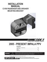
Step 1. Remove the plastic engine shroud. This is the cover that ts
over the radiator area of the engine compartment and surrounds the
hood latch. Note: It may be necessary to trim a portion of this
cover around the hood latch area before reinstalling it on the
vehicle. Then remove the entire vehicle grill and front fascia assembly
per the automobile manufacturer’s shop manual instructions. Several
fasteners are hidden so the shop manual is very helpful. For 2015+
models the engine shroud, grill, and front fascia are all part of the nose
assembly and are removed together as a single assembly.
Step 2. Remove the hood latch assembly but do not detach the cables and place the assembly o to the side. Also detach the horn
electrical wire and set it aside from the work area.
Step 3. Assemble the C3100 speaker/driver assembly to the mounting bracket as shown. Fasteners are included with the C3100 speaker
kit. Note: The arrows must point up for water to drain properly from the speaker/driver assembly. Be sure the blue and white wires
are connected to the driver.
Step 4. Where the plastic retainers were remove from the front support braces (on either side and in front of the hood latch area) slide a
5/16-18 Extruded U-Nut over each hole (supplied with the mounting kit). The front anges of the speaker mounting bracket t over these
U-Nuts and are held in place with two 5/16 at washers, two 5/16 split lock washers, and two 5/16-18x1.00 hex head bolts (also supplied with
the mounting kit).
Step 5. Attach the rear of the bracket behind the hood latch assembly using the hood latch fasteners while being careful the cables are still
attached and properly located. Note: The two marks left on the hool latch assembly created originally by the fasteners must be made
to line up again with the fasteners. This ensures the vehicle’s hood mounted latch bracket will mate up with the hood latch assembly as
originally assembled at the factory.
Step 6. Replace the horn wire in its original location and connect to the horn. Recheck the speaker/driver assembly is mounted in the up
position (so water will drain properly) and connect the blue and white wires to the siren amplier per the siren and speaker driver instructions.
Test for proper operation.
Step 7. Replace the vehicle grill and front fascia assembly per shop manual instructions. Reinstall the plastic engine shroud. Do this for the
entire nose assembly for 2015 models. Note: It may be necessary to trim a portion of the plastic engine shroud around the hood latch
assembly to t properly with the speaker bracket anges.
Installation and Mounting:
Sirens are an integral part of an eective audio/visual emergency warning system. However, sirens are only short range secondary
warning devices. The use of a siren does not insure that all drivers can or will observe or react to an emergency warning signal,
particularly at long distances or when either vehicle is traveling at a high rate of speed. Sirens should only be used in a combination
with eective warning lights and never relied upon as a sole warning signal. Never take the right of way for granted. It is your responsibility to
be sure you can proceed safely before entering an intersection driving against trac, or responding at a high rate of speed.
The eectiveness of this warning device is highly dependent upon correct mounting and wiring. Read and follow the manufacturer’s
instructions before installing this device. The vehicle operator should check the equipment daily to insure that all features of the device
operate correctly.
To be eective, sirens must produce high sound levels that potentially can inict hearing damage. Installers should be warned to wear hearing
protection, clear bystanders from the area and not to operate the siren indoors during testing. Vehicle operators and occupants should assess
their exposure to siren noise and determine what steps, such as consultation with professionals or use of hearing protection should be
implemented to protect their hearing.
This equipment is intended for use by authorized personnel only. It is the user’s responsibility to understand and obey all laws regarding
emergency warning devices. The user should check all applicable city, state and federal laws and regulations. Code 3, Inc., assumes no
liability for any loss resulting from the use of this warning device.
Proper installation is vital to the performance of the siren and the safe operation of the emergency vehicle. It is important to recognize that
the operator of the emergency vehicle is under psychological and physiological stress caused by the emergency situation. The siren system
should be installed in such a manner as to: A) Not reduce the acoustical performance of the system, B) Limit as much as practical the noise
level in the passenger compartment of the vehicle, C) Place the controls within convenient reach of the operator so that he can operate the
system without losing eye contact with the roadway.
Emergency warning devices often require high electrical voltages and/or currents. Properly protect and use caution around live electrical
connections. Grounding or shorting of electrical connections can cause high current arcing, which can cause personal injury and/or severe
vehicle damage, including re.
PROPER INSTALLATION COMBINED WITH OPERATOR TRAINING IN THE PROPER USE OF EMERGENCY WARNING DEVICES IS ESSENTIAL
TO INSURE THE SAFETY OF EMERGENCY PERSONNEL AND THE PUBLIC.
WARNING!
Sirens produce loud sounds that may damage hearing.
• Wear hearing protection when testing
• Use siren only for emergency response
• Roll up windows when siren is operating
• Avoid exposure to the siren sound outside of vehicle

Page 3 of 4
Figure 1 Figure 2
Figure 3

Page 4 of 4
Product Returns:
If a product must be returned for repair or replacement*, please contact our factory to obtain a Return Goods Authorization Number (RGA
number) before you ship the product to Code 3®, Inc. Write the RGA number clearly on the package near the mailing label. Be sure you use
sucient packing materials to avoid damage to the product being returned while in transit.
*Code 3®, Inc. reserves the right to repair or replace at its discretion. Code 3®, Inc. assumes no responsibility or liability for expenses incurred for the removal and /or reinstallation of products requiring
service and/or repair.; nor for the packaging, handling, and shipping: nor for the handling of products returned to sender after the service has been rendered.
Manufacturer Limited Warranty Policy:
Manufacturer warrants that on the date of purchase this product will conform to Manufacturer’s specications for this product (which are avail-
able from the Manufacturer upon request). This Limited Warranty extends for Sixty (60) months from the date of purchase.
DAMAGE TO PARTS OR PRODUCTS RESULTING FROM TAMPERING, ACCIDENT, ABUSE, MISUSE, NEGLIGENCE, UNAPPROVED MODIFICA-
TIONS, FIRE OR OTHER HAZARD; IMPROPER INSTALLATION OR OPERATION; OR NOT BEING MAINTAINED IN ACCORDANCE WITH THE
MAINTENANCE PROCEDURES SET FORTH IN MANUFACTURER’S INSTALLATION AND OPERATING INSTRUCTIONS VOIDS THIS LIMITED WAR-
RANTY.
Exclusion of Other Warranties:
MANUFACTURER MAKES NO OTHER WARRANTIES, EXPRESS OR IMPLIED. THE IMPLIED WARRANTIES FOR MERCHANTABILITY, QUALITY
OR FITNESS FOR A PARTICULAR PURPOSE, OR ARISING FROM A COURSE OF DEALING, USAGE OR TRADE PRACTICE ARE HEREBY EX-
CLUDED AND SHALL NOT APPLY TO THE PRODUCT AND ARE HEREBY DISCLAIMED, EXCEPT TO THE EXTENT PROHIBITED BY APPLICABLE
LAW. ORAL STATEMENTS OR REPRESENTATIONS ABOUT THE PRODUCT DO NOT CONSTITUTE WARRANTIES.
Remedies and Limitation of Liability:
MANUFACTURER’S SOLE LIABILITY AND BUYER’S EXCLUSIVE REMEDY IN CONTRACT, TORT (INCLUDING NEGLIGENCE), OR UNDER ANY
OTHER THEORY AGAINST MANUFACTURER REGARDING THE PRODUCT AND ITS USE SHALL BE, AT MANUFACTURER’S DISCRETION, THE
REPLACEMENT OR REPAIR OF THE PRODUCT, OR THE REFUND OF THE PURCHASE PRICE PAID BY BUYER FOR NON-CONFORMING PROD-
UCT. IN NO EVENT SHALL MANUFACTURER’S LIABILITY ARISING OUT OF THIS LIMITED WARRANTY OR ANY OTHER CLAIM RELATED TO
THE MANUFACTURER’S PRODUCTS EXCEED THE AMOUNT PAID FOR THE PRODUCT BY BUYER AT THE TIME OF THE ORIGINAL PURCHASE.
IN NO EVENT SHALL MANUFACTURER BE LIABLE FOR LOST PROFITS, THE COST OF SUBSTITUTE EQUIPMENT OR LABOR, PROPERTY
DAMAGE, OR OTHER SPECIAL, CONSEQUENTIAL, OR INCIDENTAL DAMAGES BASED UPON ANY CLAIM FOR BREACH OF CONTRACT, IM-
PROPER INSTALLATION, NEGLIGENCE, OR OTHER CLAIM, EVEN IF MANUFACTURER OR A MANUFACTURER’S REPRESENTATIVE HAS BEEN
ADVISED OF THE POSSIBILITY OF SUCH DAMAGES. MANUFACTURER SHALL HAVE NO FURTHER OBLIGATION OR LIABILITY WITH RESPECT
TO THE PRODUCT OR ITS SALE, OPERATION AND USE, AND MANUFACTURER NEITHER ASSUMES NOR AUTHORIZES THE ASSUMPTION OF
ANY OTHER OBLIGATION OR LIABILITY IN CONNECTION WITH SUCH PRODUCT.
This Limited Warranty denes specic legal rights. You may have other legal rights which vary from jurisdiction to jurisdiction. Some jurisdic-
tions do not allow the exclusion or limitation of incidental or consequential damages.
© 2015 Code 3, Inc. all rights reserved.
T51684 Rev. A
Warranty:
An ECCO SAFETY GROUP™ Brand
ECCOSAFETYGROUP.com
10986 North Warson Road, St. Louis, MO 63114 USA
Technical Service USA (314) 996-2800
CODE3ESG.com

Installation and Operation Instructions
CW2440 & CW2441 LED WORKLAMPS
Read all instructions and warnings before installing and using.
INSTALLER: This manual must be delivered to the end user of this equipment.
2015 DODGE CHARGER DRIVER
AND PASSENGER SIDES SHOWN
IMPORTANT:
Installation and Operation Instructions
C-3100 SPEAKER MOUNTING
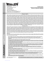
INSTALLATION PROCEDURE:
1. RAISE VEHICLE TO ACCESS UNDERSIDE OF ENGINE COMPARTMENT
2. REMOVE FRONT SPLASH GUARD BY REMOVING SCREWS AND PUSH FAST-
NERS IN PANEL. (REMOVAL OF (2) FRONT ENGINE SKID PLATE SCREWS IS
NECESSARY TO REMOVE FRONT SPLASH GUARD. IT IS NOT NECESSARY TO
REMOVE THE SKID PLATE. )
SPLASH GUARD
REMOVE 2 FRONT
SCREWS FROM
SKID PLATE
SLIDE SPLASH GUARD BACK AND REMOVE
FROM VEHICLE
SKID PLATE
PASSENGER SIDE DRIVER SIDE

3. USE TOP PLATE BRACKET WITH (2) 1/2” STUDS AS A LOCATION GUIDE FOR
DRILLING (1) 5/16” DIA HOLE THROUGH BOTTOM (2) LAYERS OF BUMPER RAIL.
THE HOLE IS ACTUALLY DRILLED THROUGH THE PLASTIC BUMPER COVER
USE TOP PLATE AS
GUIDE
DRILL (1) 5/16” DIA.
HOLE THROUGH
BOTTOM AND TOP OF
LOWER BUMPER RAIL
PROFILE
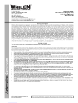
4. PLACE BOTTOM PLATE BRACKET
UNDER BUMPER RAIL AND INSERT 2.5”
CARRIAGE BOLT UP THROUGH 5/16” DIA
HOLES IN LOWER BUMPER PROFILE.
5. PLACE TOP PLATE WITH SLOT OVER
CARRIAGE BOLT END TO FORM A “CLAM
SHELL” AROUND LOWER HALF OF
BUMPER RAIL.
6. (2) 1/2” LONG 1/4” DIA STUDS ON TOP
PLATE ALIGN WITH SLOTS IN LOWER
PLATE AS SHOWN.
7. PLACE 5/16” SPLIT WASHER AND 5/16 NUT ON CARRIAGE BOLT AND TIGHTEN
WITH WRENCH UNTIL LOCK WASHER IS FULLY COMPRESSED.
8. ATTACH SPEAKER MOUNTING BRACKET ONTO SPEAKER HOUSING (MAKING
SURE SPEAKER IS CORRECTLY ORIENTATED FOR PROPER DRAINAGE.
9. PLACE SPEAKER MOUNTING BRACKET OVER 1/2” STUDS ON BUMPER AS-
SEMBLY AND INSTALL USING (2) STAINLESS STEEL KEPS NUTS PROVIDED WITH
KIT.
10. WIRE INSTALLATION AS DESIRED -
NOTE:
GRILL BRACKET LIGHTS CAN BE
EASILY INSTALLED FROM UNDER THE FRONT OF THE VEHCLE AT THE SAME
TIME WHEN SPEAKER BRACKETS ARE INSTALLED.
11. RE- INSTALL BOTTOM SPLASH GUARD.

PARTS LIST:
NO: PART NO: DESCRIPTION: QTY:
1 T17201 BOTTOM PLATE 1
2 T17202 TOP PLATE 1
3 T17203 MOUNTING BRACKET 1
4 T08863 2.5” CARRIAGE BOLT 1
5 T00244 5/16” SS HEX NUT 1
6 T00245 5/16” SS SPLIT WASH 1
7 T15105 1/4”-20 HEX KEPS NUT 2
COMPLETED INSTALLATION

WARRANTY
This product was tested and found to be operational at the time of manufacture. Provided
this product is installed and operated in accordance with the manufacturer’s recommendations,
CODE3, Inc. guarantees this product for a period of 5 years from the date of purchase or delivery,
whichever is later (does not apply to lamps). Units demonstrated to be defective within the war-
ranty period will be repaired or replaced at the factory service center at no cost.
Use of a lamp or other electrical load of a wattage higher than installed or recommended by
the factory, or use of inappropriate or inadequate wiring or circuit protection causes this warranty
to become void. Failure or destruction of the product resulting from abuse or unusual use and/or
accidents is not covered by this warranty. Use of non-CODE 3 components and assemblies may
cause damage to the system and/or personal injury, and voids all warranties.
CODE 3, Inc. shall in no way be liable for other damages including consequential, indirect or
special damages whether loss is due to negligence or breach of warranty.
CODE 3, INC. MAKES NO OTHER EXPRESS OR IMPLIED WARRANTY INCLUDING,
WITHOUT LIMITATION, WARRANTIES OF FITNESS OR MERCHANTABILITY, WITH RE‑
SPECT TO THIS PRODUCT.
Code 3 is a registered trademark of Code 3, Inc. a subsidiary of Public Safety Equipment, Inc.
Revision 0, 02/2015 - Instruction Book Part No. T56193 ©2015
CODE 3, Inc. Printed in USA
PRODUCT RETURNS
In order to provide you with faster service, if you are going to return a product for repair or re-
placement*, please contact our factory to obtain a Return Goods Authorization Number (RGA number)
before you ship the product to Code 3. Write the RGA number clearly on the package near the mailing
label. Be sure you use sufcient packing materials to avoid damage to the product being returned while
in transit.
*Code 3, Inc. reserves the right to repair or replace product at its discretion and assumes no responsibility or liability for
expenses incurred for the removal and/or reinstallation of products requiring service and/or repair.
NEED HELP? Call our Technical Assistance HOTLINE ‑ (314) 996‑2800
10986 North Warson Road
St. Louis, MO 63114
Customer Service
(314) 426-2700
www.code3esg.com
A Division of ESG
|
www.eccogroup.com
/