Page is loading ...

Page 1 of 12
Installation and Operation Instructions
Z3S
MATRIX
®
Compatible Z3™ Siren
IMPORTANT! Read all instructions before installing and using. Installer: This manual must be delivered to the end user.
WARNING!
Failure to install or use this product according to manufacturer’s recommendations may result in property damage, serious injury, and/
or death to those you are seeking to protect!
Do not install and/or operate this safety product unless you have read and understood the safety information
contained in this manual.
1. Proper installation combined with operator training in the use, care, and maintenance of emergency warning devices are essential to
ensure the safety of emergency personnel and the public.
2. Emergency warning devices often require high electrical voltages and/or currents. Exercise caution when working with live electrical
connections.
3. This product must be properly grounded. Inadequate grounding and/or shorting of electrical connections can cause high current arcing,
which can cause personal injury and/or severe vehicle damage, including re.
4. Proper placement and installation is vital to the performance of this warning device. Install this product so that output performance of
the system is maximized and the controls are placed within convenient reach of the operator so that they can operate the system without
losing eye contact with the roadway.
5. It is the responsibility of the vehicle operator to ensure daily that all features of this product work correctly. In use, the vehicle operator
should ensure the projection of the warning signal is not blocked by vehicle components (i.e., open trunks or compartment doors),
people, vehicles or other obstructions.
6. The use of this or any other warning device does not ensure all drivers can or will observe or react to an emergency warning signal.
Never take the right-of-way for granted. It is the vehicle operator’s responsibility to be sure they can proceed safely before entering an
intersection, drive against trac, respond at a high rate of speed, or walk on or around trac lanes.
7. This equipment is intended for use by authorized personnel only. The user is responsible for understanding and obeying all laws
regarding emergency warning devices. Therefore, the user should check all applicable city, state, and federal laws and regulations. The
manufacturer assumes no liability for any loss resulting from the use of this warning device.
Specications:
Size:
Control Head (HxLxD) 3.25” x 6.75” x 1.30”
Amp (HxLxD) 3.25” x 10.50” x 6.75”
Weight:
Amplier 7.6 lbs
Control Head 0.6 lbs
Input Voltage:
12 VDC Nominal
10-18 VDC Max
Input Current:
Amplier 100W: 8.5A
200W: 17.0A
300W: 25.5A
Auxiliary Outputs:
Aux A (High Current) 20A each 25A Total
Aux B (Mid Current) 10A each
25A Total
Aux C (Digital) 0.5A each
Temp. Range:
-40°F to 149°F
(-40°C to 65°C)
WARNING!
Sirens produce loud sounds that may damage hearing.
• Wear hearing protection when testing
• Use siren only for emergency response
• Roll up windows when siren is operating
• Avoid exposure to the siren sound outside of vehicle

Page 2 of 12
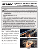
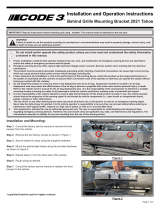
The Z3S Siren Control Head, shown in Figure 1, is designed to mount directly into the console of most leading manufacturers. It may also
be mounted above the dash, below the dash or on the transmission tunnel using the mounting hardware supplied (see Figure 2). Ease of
operation and convenience to the operator should be the prime consideration when choosing a mounting location. However, the user must
also consider the deployment area for the air bag of the vehicle and other factors which might impact the safety of the vehicle occupants.
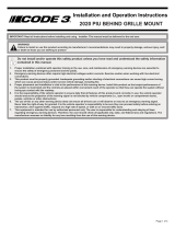
When connecting a CAT5 cable or Microphone to the back of the Z3S Siren Control Head, use tie wraps, as shown in Figure 3, to relieve
strain on the wires.
The Z3S Amplier is mounted with four screws (not supplied). Mount the Z3S Amplier so that connectors and wiring are easy to access.
NOTE: All Z3S equipment should be mounted in locations that are safe from moisture. All wiring should be routed so that it cannot
be damaged by sharp edges or moving parts.
Installation and Mounting:
Unpacking and Pre-Installation:
Carefully remove the product and place it on a at surface. Examine the unit for transit damage and locate all parts. If damage is found or
parts are missing, contact the transit company or Code 3. Do not use damaged or broken parts.
Ensure the product voltage is compatible with the planned installation.
Sirens are an integral part of an eective audio/visual emergency warning system. However, sirens are only short range secondary
warning devices. The use of a siren does not insure that all drivers can or will observe or react to an emergency warning signal,
particularly at long distances or when either vehicle is traveling at a high rate of speed. Sirens should only be used in a combination
with eective warning lights and never relied upon as a sole warning signal. Never take the right of way for granted. It is the vehicle operator’s
responsibility to be sure they can proceed safely before entering an intersection driving against trac, or responding at a high rate of speed.
The eectiveness of this warning device is highly dependent upon correct mounting and wiring. Read and follow the manufacturer’s
instructions before installing this device. The vehicle operator should check the equipment daily to insure that all features of the device
operate correctly.
To be eective, sirens must produce high sound levels that potentially can inict hearing damage. Installers should be warned to wear hearing
protection, clear bystanders from the area and not to operate the siren indoors during testing. Vehicle operators and occupants should assess
their exposure to siren noise and determine what steps, such as consultation with professionals or use of hearing protection should be
implemented to protect their hearing.
This equipment is intended for use by authorized personnel only. It is the user’s responsibility to understand and obey all laws regarding
emergency warning devices. The user should check all applicable city, state and federal laws and regulations. Code 3, Inc., assumes no
liability for any loss resulting from the use of this warning device.
Proper installation is vital to the performance of the siren and the safe operation of the emergency vehicle. It is important to recognize that
the operator of the emergency vehicle is under psychological and physiological stress caused by the emergency situation. The siren system
should be installed in such a manner as to: A) Not reduce the acoustical performance of the system, B) Limit as much as practical the noise
level in the passenger compartment of the vehicle, C) Place the controls within convenient reach of the operator so that he can operate the
system without losing eye contact with the roadway.
Emergency warning devices often require high electrical voltages and/or currents. Properly protect and use caution around live electrical
connections. Grounding or shorting of electrical connections can cause high current arcing, which can cause personal injury and/or severe
vehicle damage, including re.
PROPER INSTALLATION COMBINED WITH OPERATOR TRAINING IN THE PROPER USE OF EMERGENCY WARNING DEVICES IS ESSENTIAL
TO INSURE THE SAFETY OF EMERGENCY PERSONNEL AND THE PUBLIC.
IMPORTANT! This unit is a safety device and it must be connected to its own separate, fused power point to assure its continued operation
should any other electrical accessory fail.
CAUTION!
When drilling into any vehicle surface, make sure that the area is free from any electrical wires, fuel lines, vehicle upholstery, etc. that
could be damaged.
Figure 1 Figure 2

Page 3 of 12
The Z3S Siren acts as a central node on the Matrix network, and provides a USB interface for system congurability via PC.
All other Matrix compatible products can connect to the Z3S Siren using one or more of the four provided connections, labeled AUX4, CANP_
CANN, PRI-1, and SEC-2. For example, a Matrix compatible serial lightbar can connect to the PRI-1 port with a CAT5 cable.
NOTE: The PRI-1 port must be utilized rst, before additional products can be connected to the SEC-2 port.
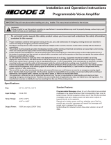
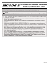
See Wiring Diagram for the details of each harness. Connect each harness from the siren to the equipment to be controlled using proper
crimping techniques and adequate wire gauges. The USB port can be used to connect the siren to a computer running the Matrix®
Congurator software.
Caution!! Do not connect anything other than a 100 watt speaker to the siren speaker outputs. This will void the siren and/or
speaker warranty!
Power Distribution:
Connect the red (power) and black (ground) wires from the Power Harness (690-0724-00) to a nominal 12 VDC supply, along with three (3)
customer supplied in-line, slow blow ATC style fuses. Use one for each red (power) wire. Each fuse must be rated for 30A. Please note that
the fuse holders selected by the customer must also be rated by the manufacturer to meet or exceed the corresponding fuse ampacity. See
the wiring diagram for details.
The Aux A Outputs are High Current; they can supply a maximum of 20A each or 25A combined. The Aux B Outputs are Mid Current; they
can supply a maximum of 10A each. The Aux C Outputs are Digital; they can supply a maximum of 0.5A each and be congured for either
Positive or Ground output. The Aux B and Aux C Outputs can supply up to 25A combined. C Outputs are digital and not designed to power
devices higher than 0.5A. Do not combine multiple C Outputs to power devices.
NOTE: Any electronic device may create or be aected by electromagnetic interference. After installation of any electronic device,
operate all equipment simultaneously to insure that operation is free of interference.
NOTE: If an AUX C Output detects 5 shorts during operation it will shut o until power is cycled. Functionality will return after
power is cycled.
Output Loads
Per Output Combined
A* 20 amps 25 amps (A1+A2)
B* 10 amps
25 amps (B+C)
C 0.5 amps
*Flashable congurable outputs
Wiring Instructions:
Figure 3
NOTE: This unit is programmable using the Matrix software. Reference the Matrix Software installation manual (920-0731-00)
for more details. The latest version of Matrix can be downloaded at this link: http://software.code3esg.global/updater/matrix/
downloads/Matrix.exe

Page 4 of 12
Wiring Diagram:
18GA
10A FUSED
10A FUSED
10A FUSED
10A FUSED
10A FUSED
10A FUSED
10A FUSED
10A FUSED
AUXB1
AUXB2
AUXB3
AUXB4
AUXB8
AUXB7
AUXB6
AUXB5
MID CURRENT OUTPUT HARNESS
690-0726-00
18GA
AUXC1
AUXC2
AUXC3
AUXC4
PRI SPK 1
PRI SPK 2
AUXC8
AUXC7
AUXC6
AUXC5
DIGITAL OUTPUT HARNESS
690-0727-00
14GA
AUXA1
AUXA2
HIGH CURRENT OUTPUT HARNESS
690-0725-00
(TAN)
(VIOLET)
(GREEN)
(GRAY)
(YELLOW)
(BLUE)
(TAN W/BLK)
(VIOLET W/BLK)
(BROWN W/BLK)
(ORANGE W/BLK)
(TAN W/BLK)
(VIOLET W/BLK)
(WHITE)
(GRAY W/BLK)
(YELLOW W/BLK)
(BLUE W/BLK)
(GREEN W/BLK)
(WHITE W/BLK)
(ORANGE)
(BROWN)
+12VDC
GND
(RED)
(BLACK)
(RED)
(RED)
+12VDC
+12VDC
10GA
POWER INPUT HARNESS
690-0724-00
+
-
BATTERY
+12V
* USER SUPPLIED (SEE WARNINGS IN THE WIRING INSTRUCTIONS SECTION)
18GA
RRB1
RRB2
TO RRB
690-0728-00
(YELLOW)
(YELLOW W/BLK)
HORN
GND
BREAK CONNECTION
HORN RING
HORN RELAY
(WHITE)
(BLUE)
TO INPUTS
IN2
IN1
(PURPLE)
(ORANGE)
IN4
IN3
(PURPLE W/BLK)
(ORANGE W/BLK)
IN6
IN5
(GRAY W/BLK)
(GRAY)
IN8
IN7
(BROWN)
(PINK W/WHT)
IN11
IN10(PURPLE W/WHT)
(ORANGE W/WHT)
IN13
IN12(BLUE W/WHT)
(GRAY W/WHT)
IN9
IN14(BROWN W/WHT)
(GREEN W/WHT)
22GA
CANP
CANN
BARE WIRE
TO CONTROL HEAD
TO AUX 4 PIN DEVICE
USB TO MICRO USB
PRI - 1SEC - 2
INPUT/HORN RING/RRB
DIGITAL
MID
HIGH
POWER
CAN
AUX 4 PIN
USB
KEY W/ P.A.
PRIMARY SPEAKER/
CURRENT
CURRENT
AUX A
AUX B AUX C
100W 100W
SPEAKER 1 SPEAKER 3
TO HORN
TO HORN
INTERFACE
HARNESS
HORN RING
HORN RELAY
T56925
690-0769-00
NOT INCLUDED
TO MATRIX CONNECTED DEVICE
TO MATRIX CONNECTED DEVICE
690-0769-00
690-0769-00
NOTE: The SEC – 2 port
should only be used if the
PRI – 1 port is already in use.
C OUTPUTS
B OUTPUTS
A OUTPUTS
30A
Fuse*
30A
Fuse*
30A
Fuse*
SECONDARY
SPEAKER
SEC SPEAKER
(20A FUSE)
100W
SPEAKER 2
SEC SPK 2
SEC SPK 1
(RED)
(BLACK)
690-0721-00
SECONDARY OUTPUT HARNESS

Page 5 of 12
Device Functionality:
Control Head - Default Functions
Input Type Function Network
Slide/Alert 0 Toggle Tones OFF Alert 0
Slide/Alert 1 Toggle
AUX C5 = POSITIVE
AUX C6 = POSITIVE
Alert 1 + Lighting 1
Slide/Alert 2 Toggle
AUX C5 = POSITIVE
AUX C6 = POSITIVE
AUX A1 = POSITIVE
Horn Ring = ENABLED
Alert 2 + Lighting 2
Slide/Alert 3 Toggle
AUX C5 = POSITIVE
AUX C6 = POSITIVE
AUX A1 = POSITIVE
AUX A2 = POSITIVE
Horn Ring = ENABLED
Alert 3 + Lighting 3
Rotary 0 Toggle Tones OFF Alert 0
A1/Rotary 1 Toggle
Horn Ring = ENABLED
Primary/Hit-N-Go: WAIL/YELP
Secondary/Hit-N-Go: YELP/LOW FREQ YELP
A2/Rotary 2 Toggle
Horn Ring = ENABLED
Primary/Hit-N-Go: YELP/HYPER-YELP 1
Secondary/Hit-N-Go: HYPER-YELP 1/LOW FREQ YELP
A3/Rotary 3 Toggle
Horn Ring = ENABLED
Primary/Hit-N-Go: HI-LO 1/COMMAND ALERT
Secondary/Hit-N-Go: HYPER-LO 1/LOW FREQ YELP
A4 Momentary
Slide/Alert 3 AUX Outs
Horn Ring = ENABLED
Primary: MECHANICAL MANUAL WAIL 1
Secondary: MECHANICAL MANUAL WAIL 1
Alert 3 + Lighting 3
A5 Momentary
Slide/Alert 3 AUX Outs
Primary: AIRHORN 1
Secondary: AIRHORN 2
Alert 3 + Lighting 3
B1 Toggle AUX B1 = ON Left Alley
B2 Toggle AUX B2 = ON Right Alley
B3 Toggle AUX B3 = ON Center TD
B4 Toggle AUX B4 = ON Full Scene
B5 Toggle AUX B5 = ON Left Corners Scene
B6 Toggle AUX B6 = ON Right Corners Scene
B7 Timed AUX B7 = ON
B8 Toggle AUX B8 = ON
C1 Toggle AUX C1 = ON Arrowstik Left Build Fast
C2 Toggle
AUX C1 = ON
AUX C2 = ON
Arrowstik Center Build Fast
C3 Toggle AUX C2 = ON Arrowstik Right Build Fast
C5 Toggle AUX C4 = ON Simultaneous Flash
C4 Toggle AUX C3 = ON DIM

Page 6 of 12
Discrete Input - Default Functions
Input Color Function Active
IN 1 ORANGE HANDS-FREE POSITIVE
IN 2 PURPLE CONFIGURABLE GROUND
IN 3 ORANGE/BLACK PARK KILL GROUND
IN 4 PURPLE/BLACK ALARM POSITIVE
IN 5 GRAY RRB POSITIVE
IN 6 GRAY/BLACK IGNITION POSITIVE
IN 7 PINK/WHITE AUX C7 = GROUND POSITIVE
IN 8 BROWN CONFIGURABLE POSITIVE
IN 9 ORANGE/WHITE CONFIGURABLE POSITIVE
IN 10 PURPLE/WHITE CONFIGURABLE POSITIVE
IN 11 GRAY/WHITE CONFIGURABLE POSITIVE
IN 12 BLUE/WHITE CONFIGURABLE POSITIVE
IN 13 GREEN/WHITE CONFIGURABLE POSITIVE
IN 14 BROWN/WHITE CONFIGURABLE POSITIVE
RRB IN 1 YELLOW
RRB INPUTS
N/A
RRB IN 2 YELLOW/BLACK N/A
HORN RING WHITE HORN RING INPUT GROUND
HORN RELAY BLUE HORN RING TRANSFER RELAY N/A
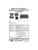
Control Head - Menus
Menu Access Functionality
Backlight Level
Push and hold C1 or C3 while in Alert Level 0.
C2 will illuminate while menu is active.
Release C1, C3.
Press and hold C1 to decrease backlight level.
Press and hold C3 to increase backlight level.
Press C5 to exit the menu.
RRB Volume
Drive INPUT 5 (Gray) high.
Then push and hold C1 or C3 while in Alert Level 0.
C2 will illuminate while menu is active.
Release C1, C3.
Press and hold C1 to decrease RRB volume.
Press and hold C3 to increase RRB volume.
Press C5 to exit the menu.
PA Volume
Hold the PTT button on the microphone.
Then push and hold C1 or C3 while in Alert Level 0.
C2 will illuminate while menu is active.
Release C1, C3.
Press and hold C1 to decrease PA volume.
Press and hold C3 to increase PA volume.
Press C5 to exit the menu.
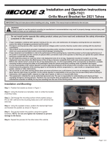
Figure 4 - Rotary Control Head Key Figure 5 - Push Button Control Head Key

Page 7 of 12
Feature Descriptions:
The information below describes the features of the Z3S(X) Siren system. Many of these features are congurable using the Matrix
Congurator. See software manual 920-0731-00 for further information.
Siren Priority – Audible siren outputs conform to the following priority order from highest to lowest; PTT/PA, RRB, Airhorn tones, Alarm
function, Manual tones, remaining tones (e.g. Wail, Yelp, Hi-Lo).
Hands-Free – This mode enables the Scroll functionality, as well as Alert Level 3 lighting, in response to the vehicle’s horn input. To enable
this mode, apply Positive voltage to the discrete wire input IN 1 (Orange).
Horn Ring – This input allows the Z3S siren to respond to the vehicle horn press. See the Wiring Diagram for details. This input is only
enabled in Alert Level 2 or above, and when tones are active, by default. When enabled the vehicle’s horn input is replaced by siren tones.
Hit-N-Go – This mode overrides an active siren tone for eight (8) seconds. It can be enabled by the Horn Ring input.
Note: The Horn Ring input cannot enable Hit-N-Go mode if the Hands Free mode is active. The specic override tones are outlined
in the Control Head - Default Functions table.
Scroll – This function loops through a list of push button inputs and must be congured via software. When active, a dened input will
advance to the next available push button, e.g. A1 -> A2 -> A3 -> A1. By default, this input is the short press Horn Ring. If no tone is active,
A1 will be selected. A long press Horn Ring will turn on an Airhorn tone. To stop the function loop, press the currently active push button.
Note: in Hands Free mode a long press will instead disable the current push button input.
Scroll On/O – This mode is similar to the Scroll mode except that is inserts an OFF state at the end of the push button input list. This mode
must also be congured via software.
Overvoltage Lockout – This function monitors system supply voltages to prevent speaker damage. Supply voltages greater than 15V will
shuto siren tones per the table below. The siren tones can be turned on again after shuto by reactivating the input. This will reset the
overvoltage timer. See software manual 920-0731-00 for further information.
Supply Voltage Duration
15 - 16 VDC 15 min.
16 - 17 VDC 10 min.
17 - 18 VDC 5 min.
18+ VDC 0 min.
LightAlert – This function produces an audible noise from the Control Head on a periodic basis if any lighting or auxiliary outputs are enabled.
Sleep – This mode allows the siren to enter a low power state when the vehicle is turned o. Removing Positive from the Ignition input starts
a timer which lasts one (1) hour by default. The Z3S siren enters Sleep mode whenever the timer runs out. Reapplying Positive to the Ignition
input will prevent the siren from going to sleep.
Overcurrent Lockout – This function monitors tone output currents to prevent siren damage. If a short circuit is detected, the corners of the
ArrowStik Indicator on the control head will ash RED momentarily to warn the operator. The tone output will be disabled for 10 seconds
before retry.
Radio Rebroadcast (RRB) – This mode allows a user to rebroadcast an audio signal over the siren speakers. Siren tones do not operate
when this mode is enabled. Connect the audio signal to the RRB 1 and RRB 2 discrete inputs (Yellow and Yellow/Black). Polarity is not an
issue. The mode can be enabled by applying Positive to discrete input IN 5 (Gray). The volume of the output can be adjusted using the RRB
volume menu. See the Control Head - Menus table for more details.
Push-To-Talk (PTT) – Select the momentary button on the side of the microphone to switch the siren outputs to the Public Address (PA)
mode. This will override all other active tone outputs until the button is released.
Public Address (PA) – This mode allows a user to broadcast their voice over the siren speakers. This takes priority over all other siren tone
functions. The mode can be enabled by pushing the PTT button. The volume of the output can be adjusted using the PA volume menu. See
the Control Head - Menus table for more details.
Microphone Lockout – This function disables the PA mode if the PTT input is held for 30 seconds. This will avoid the situation where the PTT
is stuck in the on position for an extended period. To continue using PA mode, release the PTT button and press it again.

Page 8 of 12
Fuse Indicators – All fuses are accessible from outside the siren housing. An open fuse is indicated with a RED LED located next to the fuse.
In the event of an open fuse, the corners of the ArrowStik Indicator will momentarily ash RED to warn the operator.
Note: The fuse LED for the Secondary Siren output on a Z3SX system will illuminate GREEN under normal operation.
Park Kill – This function enables the Standby mode. To enable this function, apply Ground to the discrete wire input IN 3 (Orange/Black).
When Park Kill is disabled, active tones will remain in Standby. Airhorn tones and the Alarm function are not aected by Standby mode.
Alarm – This function will output an Alarm Chirp tone. To enable this function, apply Positive to the discrete wire input IN 4 (Purple/Black).
For example, this can be used to alarm the police ocer when a temperature sensor on a K-9 unit has reached dangerous levels. The Alarm
input will operate even in Sleep Mode.
Ignition – This function controls the Sleep Mode of the siren. Apply Positive to the discrete input IN 6 (Gray/Black) to exit Sleep Mode. A USB
cable between the siren and a PC running the Matrix Congurator will also exit Sleep Mode.
Note: One (1) minute after communication with the software is terminated the system will reset.
ArrowStik Indicator – The LEDs located in the upper right corner of the control head indicate the current status of any trac director on the
Matrix network. They are also used to indicate system faults: the far left and right arrows will momentarily ash RED in the presence of a
fault. They are also used to display menu information.
Standby – This mode disables siren tones and prevents the Matrix network from being in Alert 3. A Control Head tone button that is aected
will begin to blink at a steady rate when this mode is enabled. All functions, except siren tones, will resume immediately on exiting Standby
mode. A short press will re-enable the tone button once Standby is removed, or a long press will turn the tone o permanently.
Manual Tones – This function produces a manual style tone when enabled. A manual tone will ramp up to its maximum frequency and hold
until the input is released. When the input is released the tone will ramp down and return to the previous function. If the button is pressed
again before the ramp down is completed, the tone will start ramping up again from the current frequency. If another tone is active the
Manual Tones will take priority per the Siren Priority.
Positive – A voltage applied to an input wire that is 10V or greater.
Ground – A voltage applied to an input wire that is 1V or less.
Alert 0/1/2/3 (Level 0/1/2/3) – These modes group default functions together for one touch access, e.g. slide switch position. By default, there
are three (3) available groups. These groups can be modied. See software manual 920-0731-00 for further information.
Brownout Condition – This function allows the Matrix network to recover from an extended low voltage condition. Recovery time is ve (5)
seconds or less once the Brownout Condition is relieved. The control head will beep three times. Functions operating prior to the Brownout
Condition will not automatically resume.
Button Input Types:
Timed – Active on press; inactive after dened duration or next press
Toggle – Active on press; inactive after next press
Momentary – Active while held; inactive on release

Page 9 of 12
Troubleshooting:
Problem Possible Cause(s) Comments / Response
No Power Power Wiring Ensure power and ground connections to the Siren are secured.
Ensure input voltage does not exceed the range of 10-16 VDC.
Remove and reconnect the power wire harness.
Blown Fuse / Reverse Polarity Check and replace the fuse(s) feeding the power wire harness if
necessary. Verify the correct power wire polarity.
Ignition Input The Ignition wire input is required to bring the Siren out of a Sleep
mode. Ensure that the Ignition wire is connected properly. Note that
the Siren will revert to a Sleep mode after a default 1 hour time period
if Ignition is removed. Driving the Ignition wire high again will resume
active operation. Connecting the Siren to the Matrix Congurator via
USB will keep the network active while the software is active.
No Communication Connectivity Ensure that all other Matrix devices are securely connected to the
Siren. For example, ensure that the CAT5 cable(s) are fully seated
into the RJ45 jacks with positive lock.
No Siren Tones Park Kill Shift the vehicle out of park to exit Park Kill. Press the desired tone
input to exit Standby.
Overcurrent Lockout The corners of the ArrowStik Indicator will ash RED momentarily
to warn the operator of a short circuit condition. Check the speaker
wiring and condition. Replace as needed.
Overvoltage Lockout See Feature Descriptions section for more detail. Monitor the vehicle
supply during operation.
PA/RRB The PA and RRB function both override normal siren operation.
Release the PTT button or remove the signal from the RRB input.
Defective Speaker(s) Verify resistance across the speaker(s) in the range of 4Ω - 6Ω.
Replace speaker(s) as necessary.
Siren Temperature Siren tone outputs shut o at an over temperature threshold. This
allows the system to cool, and avoid damage to the components.
Once temperatures decrease, the siren tones will resume operation.
Speaker Wiring Check speaker harness wiring. Ensure positive lock, proper
connections, and continuity. Ensure that tones are heard from within
the siren enclosure when active.
Open Siren Fuse Defective Speaker(s) Verify resistance across the speaker(s) in the range of 4Ω - 6Ω.
Replace speaker(s) as necessary.
Auxiliary A/B/C Output Overcurrent See Specications / Auxiliary Outputs for output type current limits.
Ensure that each output type does not exceed its rating.
Siren Tone Quality Low Supply Voltage Ensure power and ground connections to the Siren are secured. If an
aftermarket power distribution system is installed, ensure that its rated
current capacity is sucient for all downstream loads.
Speaker Wiring Check speaker harness wiring. Ensure positive lock, proper
connections, and continuity. Ensure that tones are heard from within
the siren enclosure when active.
Speaker Arrangement Multiple speakers on the same output harness must be installed in
parallel. Refer to Wiring Diagram for details.
Defective Speaker(s) Verify resistance across the speaker(s) in the range of 4Ω - 6Ω.
Replace speaker(s) as necessary.
Premature Speaker Failure High Supply Voltage Verify proper operation of the vehicle charging system. Supply
voltage in excess of 15V will induce the Overvoltage Lockout.
Speaker Type Only 100W speakers are permitted. Contact customer support for a
list of approved speakers/speaker ratings.

Page 10 of 12
Problem Possible Cause(s) Comments / Response
Auxiliary Output Failure Output Wiring Check output harness wiring. Ensure positive lock, proper
connections, and continuity.
Output Load Verify that the load is not shorted. All outputs are designed to self
current limit in case of short circuit. In some cases, this may prevent
an open fuse. See Specications / Auxiliary Outputs for output
type current limits. Ensure that each output type does not exceed
its rating. AUX C Outputs may require full power cycle if shorted
repeatedly.
PA Quality PA Volume See the Control Head - Menus table for more details.
Microphone Connection Check microphone wiring. Ensure positive lock, proper connections,
and continuity.
Defective Microphone Test the siren with another microphone.
Microphone Lockout This function disables the PA mode if the PTT input is held for 30
seconds. This will avoid the situation where the PTT is stuck in the on
position for an extended period. To continue using PA mode, release
the PTT button and press it again.
Microphone Type Contact customer support for a list of approved microphones.
RRB Quality RRB Volume See the Control Head - Menus table for more details.
Audio Signal Connection Check microphone wiring. Ensure positive lock, proper connections,
and continuity.
Audio Signal Amplitude Ensure that the audio source volume is high enough. Turn up the
source volume as necessary.
Control Head Connectivity Ensure that the CAT5 cable from the control head is fully seated
into the RJ45 jack on both ends. Note that the control head jack is
labeled ‘KEY w/ PA’. Replace the cable if necessary.
Sleep mode Ensure that the Ignition wire is connected properly, and Positive is
applied.
Fault LEDs The LEDs located in the upper right corner of the control head
are used to indicate system faults: the far left and right arrows will
momentarily ash RED in the presence of a fault.
Park Kill Buttons will ash slowly if the associated functions are on Standby.
Shift the vehicle out of park to exit Park Kill. Then press the desired
tone input to exit Standby.
Conguration Error Connect the siren to the Matrix Congurator and reload the desired
system conguration.
Unexpected Operation
(Misc)
Scroll Verify that the Horn Ring input is not inadvertently triggered. This
could cause the system to enter Scroll mode.
Conguration Error Connect the siren to the Matrix Congurator and reload the desired
system conguration.

Page 11 of 12
All replacement parts and accessories pertaining to the product will be placed in a chart with their description and part numbers. Below is an
example of a Replacement/Accessories chart.
Description Part No.
Z3S PUSH BUTTON CONTROL HEAD CZPCH
Z3S ROTARY CONTROL HEAD CZRCH
Z3S HARNESS CZZ3SH
Z3S LEGEND SET CZZ3SL
Z3S SIREN MICROPHONE CZZ3SMIC
CAT5 Splitter Z3-SPLIT
Replacement Parts and Accesories:

Page 12 of 12
Product Returns:
If a product must be returned for repair or replacement*, please contact our factory to obtain a Return Goods Authorization Number (RGA
number) before you ship the product to Code 3®, Inc. Write the RGA number clearly on the package near the mailing label. Be sure you use
sucient packing materials to avoid damage to the product being returned while in transit.
*Code 3®, Inc. reserves the right to repair or replace at its discretion. Code 3®, Inc. assumes no responsibility or liability for expenses incurred for the removal and /or reinstallation of products requiring
service and/or repair.; nor for the packaging, handling, and shipping: nor for the handling of products returned to sender after the service has been rendered.
Manufacturer Limited Warranty Policy:
Manufacturer warrants that on the date of purchase this product will conform to Manufacturer’s specications for this product (which are avail-
able from the Manufacturer upon request). This Limited Warranty extends for Sixty (60) months from the date of purchase.
DAMAGE TO PARTS OR PRODUCTS RESULTING FROM TAMPERING, ACCIDENT, ABUSE, MISUSE, NEGLIGENCE, UNAPPROVED MODIFICA-
TIONS, FIRE OR OTHER HAZARD; IMPROPER INSTALLATION OR OPERATION; OR NOT BEING MAINTAINED IN ACCORDANCE WITH THE
MAINTENANCE PROCEDURES SET FORTH IN MANUFACTURER’S INSTALLATION AND OPERATING INSTRUCTIONS VOIDS THIS LIMITED WAR-
RANTY.
Exclusion of Other Warranties:
MANUFACTURER MAKES NO OTHER WARRANTIES, EXPRESS OR IMPLIED. THE IMPLIED WARRANTIES FOR MERCHANTABILITY, QUALITY
OR FITNESS FOR A PARTICULAR PURPOSE, OR ARISING FROM A COURSE OF DEALING, USAGE OR TRADE PRACTICE ARE HEREBY EX-
CLUDED AND SHALL NOT APPLY TO THE PRODUCT AND ARE HEREBY DISCLAIMED, EXCEPT TO THE EXTENT PROHIBITED BY APPLICABLE
LAW. ORAL STATEMENTS OR REPRESENTATIONS ABOUT THE PRODUCT DO NOT CONSTITUTE WARRANTIES.
Remedies and Limitation of Liability:
MANUFACTURER’S SOLE LIABILITY AND BUYER’S EXCLUSIVE REMEDY IN CONTRACT, TORT (INCLUDING NEGLIGENCE), OR UNDER ANY
OTHER THEORY AGAINST MANUFACTURER REGARDING THE PRODUCT AND ITS USE SHALL BE, AT MANUFACTURER’S DISCRETION, THE
REPLACEMENT OR REPAIR OF THE PRODUCT, OR THE REFUND OF THE PURCHASE PRICE PAID BY BUYER FOR NON-CONFORMING PROD-
UCT. IN NO EVENT SHALL MANUFACTURER’S LIABILITY ARISING OUT OF THIS LIMITED WARRANTY OR ANY OTHER CLAIM RELATED TO
THE MANUFACTURER’S PRODUCTS EXCEED THE AMOUNT PAID FOR THE PRODUCT BY BUYER AT THE TIME OF THE ORIGINAL PURCHASE.
IN NO EVENT SHALL MANUFACTURER BE LIABLE FOR LOST PROFITS, THE COST OF SUBSTITUTE EQUIPMENT OR LABOR, PROPERTY
DAMAGE, OR OTHER SPECIAL, CONSEQUENTIAL, OR INCIDENTAL DAMAGES BASED UPON ANY CLAIM FOR BREACH OF CONTRACT, IM-
PROPER INSTALLATION, NEGLIGENCE, OR OTHER CLAIM, EVEN IF MANUFACTURER OR A MANUFACTURER’S REPRESENTATIVE HAS BEEN
ADVISED OF THE POSSIBILITY OF SUCH DAMAGES. MANUFACTURER SHALL HAVE NO FURTHER OBLIGATION OR LIABILITY WITH RESPECT
TO THE PRODUCT OR ITS SALE, OPERATION AND USE, AND MANUFACTURER NEITHER ASSUMES NOR AUTHORIZES THE ASSUMPTION OF
ANY OTHER OBLIGATION OR LIABILITY IN CONNECTION WITH SUCH PRODUCT.
This Limited Warranty denes specic legal rights. You may have other legal rights which vary from jurisdiction to jurisdiction. Some jurisdic-
tions do not allow the exclusion or limitation of incidental or consequential damages.
© 2018 Code 3, Inc. all rights reserved.
920-0663-00 Rev. H
Warranty:
10986 North Warson Road
St. Louis, MO 63114
Technical Service
USA (314) 996-2800
Customer Service
UK +44 (0)113 237 5340
AUS +61 (0)3 63322444
www.code3esg.com
An ECCO SAFETY GROUP™ Brand
www.eccosafetygroup.com
/