Page is loading ...

INSTALLATION
MANUAL
C3100 PASSENGER SIDE SPEAKER
MOUNTING BRACKET
Read all instructions and warnings before installing and using.
This manual must be delivered to the end user of this equipment.
IMPORTANT:
Installation & Mounting.........................................................2-4
Parts List...............................................................................5
Notes:...................................................................................6-7
Warranty................................................................................8
CONTENTS:
For future reference record your product's serial no. here __________________________________________
INSTALLER:
2005 - PRESENT IMPALA PPV
Utilizing non-factory supplied screws and/or mounting brackets and/or the improper number of
screws may result in loss of warranty coverage on the equipment.
WARNING!

2
Installation Instructions:
Step 1. Remove the passenger side head light by pulling up and removing the white plastic retention clip (See Figure
-1). Remove the single mounting screw at the passenger side fender using a 7 mm hex socket wrench (See Figure -2).
Pull the head light out, unplug the wiring connector & set the head light, clip, & mounting screw aside.
FIGURE -1 FIGURE -2
Step 2. Remove the OEM horn assembly mounting screw with a 10 mm hex socket (See Figure -3). Take note as to
which horn is the top horn and which is the bottom. Unplug the horn connector and set the horn assembly aside.
Tuck the head light & horn wires & their connectors back in the fender to provide more room to install the speaker.
Step 3. Remove the (2) Vehicle bumper bolts using a 13 mm socket (See Figure -4).
Step 4. Position the Speaker Mounting bracket inside the side of the vehicle's frame as shown in Figure -5 and locate
the existing hole in the side of the vehicle's frame which will be behind the slot in the Speaker Mounting Bracket shown
in Figure -6. Note: The hole in the vehicle's frame is covered up by a bar code sticker. Take a small Phillips screw
driver or punch and poke a hole through the bar code sticker. Once you have located the existing hole in the vehicle's
frame, using a 10 mm socket, thread the supplied 1/4" X 5/8" Long Slot/Hex head sheet metal screw into the hole in the
side of the vehicle's frame (See Figure -7 -Shown with Speaker Mounting Bracket in place for clarity only) until the
screw has created a thread in the vehicle's frame sheet metal. Thread the screw in until it is almost bottomed out but not
fully tightened. Remove the screw for later steps in the process.
Step 5. Attach the C3100 Speaker to the mounting bracket using the (4) supplied #12 Phillips Pan Head Screws with (4)
1/4" internal tooth star washers (See Figure 8). NOTE: The speaker must be oriented with the speaker wires exit-
ing the bottom of the speaker and the CAUTION label at the top (See Figure -9 on page 3). The exit holes for the
wires are also the speaker drain holes. Failure to mount the speaker in this orientation will void all warranties!
FIGURE -3 FIGURE -4 FIGURE -5
FIGURE -6 FIGURE -7 FIGURE -8

3
Installation Instructions - Cont:
Step 6. Drop the speaker assembly into the headlight cavity (See Figure -10) then rotate the speaker bracket mounting
ange forward & down into the headlight cavity while lowering the speaker deeper into the space below the headlight
(See Figure -11). NOTE: The vehicle's exible plastic front shroud and it's parts below will ex out of the way to
allow the speaker assembly to drop into position. Space is tight but it will t!
Step 7. Once the bracket is in position, thread the bumper bolts back into their holes (see Figure -12). Lift up on the
speaker and thread the supplied 1/4" X 5/8" Long Slot/Hex head sheet metal screw through the slot in the Speaker
Mounting Bracket and into the hole in the side of the vehicle's frame (See Arrow in Figure -13).
Step 8. Tighten up the bumper bolts and remove the 1/4" X 5/8" Long Slot/Hex head screw for the next step.
Step 9. Again take note and keep track of which horn is the bottom and which is the top, remove the hex nuts fastening
the horns to the vehicle's OEM horn mounting bracket (See Figures 14 & 15). Discard the OEM horn bracket. Mount
the horns to the supplied Horn Relocation/Mounting Bracket as shown in Figure -16 (Attach the TOP HORN rst) &
Figure -17 (BOTTOM HORN). Only tighten the horn fastening nuts nger tight at this time so they can be adjusted later.
FIGURE -9 FIGURE -10 FIGURE -11
FIGURE -12 FIGURE -13 FIGURE -14 - BOTTOM HORN
FIGURE 15 - TOP HORN FIGURE -16 - TOP HORN FIGURE -17 - BOTTOM HORN

4
Larger wires and tight connections will provide longer service life for components. For high current wires it
is highly recommended that terminal blocks or soldered connections be used with shrink tubing to protect
the connections. Do not use insulation displacement connectors (e.g. 3M
®
Scotchlock type connectors).
Route wiring using grommets and sealant when passing through compartment walls. Minimize the
number of splices to reduce voltage drop. High ambient temperatures (e.g. under hood) will signicantly
reduce the current carrying capacity of wires, fuses, and circuit breakers. Use "SXL" type wire in engine
compartment. All wiring should conform to the minimum wire size and other recommendations of the
manufacturer and be protected from moving parts and hot surfaces. Looms, grommets, cable ties, and
similar installation hardware should be used to anchor and protect all wiring. Fuses or circuit breakers
should be located as close to the power takeoff points as possible and properly sized to protect the wiring
and devices. Particular attention should be paid to the location and method of making electrical connections
and splices to protect these points from corrosion and loss of conductivity. Ground terminations should
only be made to substantial chassis components, preferably directly to the vehicle battery. The user should
install a fuse sized to approximately 125% of the maximum Amp capacity in the supply line to protect
against short circuits. For example, a 30 Amp fuse should carry a maximum of 24 Amps. DO NOT USE
1/4" DIAMETER GLASS FUSES AS THEY ARE NOT SUITABLE FOR CONTINUOUS DUTY IN SIZES
ABOVE 15 AMPS. Circuit breakers are very sensitive to high temperatures and will "false trip" when
mounted in hot environments or operated close to their capacity.
WARNING!
Installation Instructions - Cont:
Step 10. Reconnect the wiring connector to the bottom horn. Position the New Horn Assembly with both horn ares
facing down as shown in Figure -18. Thread the supplied 1/4" X 5/8" Long Slot/Hex head sheet metal screw with a sup-
plied 1/4" internal tooth star washer through the mounting hole in the Horn Relocation/Mounting Bracket and into the
threaded hole in the vehicle's frame from Step -4. Tighten the screw using a 10 mm socket making sure that the top of
the Horn Relocation/Mounting Bracket is up against the under side of the vehicle's frame ange (see Figure -18). Posi-
tion the horns so that they aim down and slightly to the rear of the vehicle and tighten the horn retention nuts to secure
the horns in place. Note: The top and bottom horns should not be touching each other or anything around them.
Step 11. Route the speaker wires as desired. Connect the speaker leads to the siren according to the siren install
manual.
Step 12. Re install the vehicle's head light.
FIGURE -18

5
Item No Part Description Qty: Part Number
1 C3100 Speaker Mounting Bracket-Passenger Side 2005+Impala 1 T17154
2 C3100 Speaker Assembly 1 S71684
3 Horn Relocation/Mounting Bracket 1 T17155
4 1/4" X 5/8" Long Slot Hex Washer Head SMS STL Zinc 1 T16222
5 1/4" Internal Tooth Star Washer 5 T11253
6 #12 X 1" Long Phillips Pan Head SMS - 18-8 SS 4 T11247
PARTS LIST:
1
2
3
6
5
4
5
4

6
NOTES:

7
NOTES:

8
WARRANTY
This product was tested and found to be operational at the time of manufacture. Provided this product
is installed and operated in accordance with the manufacturer's recommendations, CODE 3, Inc. guarantees
this product for a period of 5 years from the date of purchase or delivery, whichever is later (does not apply to
lamps). Units demonstrated to be defective within the warranty period will be repaired or replaced at the factory
service center at no cost.
Use of a lamp or other electrical load of a wattage higher than installed or recommended by the factory,
or use of inappropriate or inadequate wiring or circuit protection causes this warranty to become void. Failure
or destruction of the product resulting from abuse or unusual use and/or accidents is not covered by this war-
ranty. Use of non-CODE 3, Inc. components and assemblies may cause damage to the system and/or personal
injury, and voids all warranties.
CODE 3, Inc. shall in no way be liable for other damages including consequential, indirect or special
damages whether loss is due to negligence or breach of warranty.
CODE 3, INC. MAKES NO OTHER EXPRESS OR IMPLIED WARRANTY INCLUDING, WITHOUT LIMI-
TATION, WARRANTIES OF FITNESS OR MERCHANTABILITY, WITH RESPECT TO THIS PRODUCT.
Code 3 is a registered trademark of Code 3, Inc. a subsidiary of Public Safety Equipment, Inc.
Revision - 0, 08/2014 - Instruction Book Part No. T17156
©2014 CODE 3, Inc. Printed in USA
CODE 3, Inc.
10986 N. Warson Road
St. Louis, Missouri 63114-2029—USA
Ph. (314) 426-2700 Fax (314) 426-1337
www.code3pse.com
PRODUCT RETURNS
In order to provide you with faster service, if you are going to return a product for repair or replacement*,
please contact our factory to obtain a Return Goods Authorization Number (RGA number) before you ship the
product to Code 3. Write the RGA number clearly on the package near the mailing label. Be sure you use suf-
cient packing materials to avoid damage to the product being returned while in transit.
*Code 3, Inc. reserves the right to repair or replace product at its discretion and assumes no responsibility or liability for expenses
incurred for the removal and/or reinstallation of products requiring service and/or repair.
Problems or Questions? Call our Technical Assistance HOTLINE - (314) 966-2800

Page 1 of 4
Installation and Operation Instructions
IMPORTANT! Read all instructions before installing and using. Installer: This manual must be delivered to the end user.
WARNING!
Failure to install or use this product according to manufacturer’s recommendations may result in property damage, serious injury, and/
or death to those you are seeking to protect!
Do not install and/or operate this safety product unless you have read and understood the safety information
contained in this manual.
1. Proper installation combined with operator training in the use, care, and maintenance of emergency warning devices are essential to
ensure the safety of emergency personnel and the public.
2. Emergency warning devices often require high electrical voltages and/or currents. Exercise caution when working with live electrical
connections.
3. This product must be properly grounded. Inadequate grounding and/or shorting of electrical connections can cause high current arcing,
which can cause personal injury and/or severe vehicle damage, including re.
4. Proper placement and installation is vital to the performance of this warning device. Install this product so that output performance of
the system is maximized and the controls are placed within convenient reach of the operator so that they can operate the system without
losing eye contact with the roadway.
5. Do not install this product or route any wires in the deployment area of an air bag. Equipment mounted or located in an air bag
deployment area may reduce the eectiveness of the air bag or become a projectile that could cause serious personal injury or death.
Refer to the vehicle owner’s manual for the air bag deployment area. It is the responsibility of the user/operator to determine a suitable
mounting location ensuring the safety of all passengers inside the vehicle particularly avoiding areas of potential head impact.
6. It is the responsibility of the vehicle operator to ensure daily that all features of this product work correctly. In use, the vehicle operator
should ensure the projection of the warning signal is not blocked by vehicle components (i.e., open trunks or compartment doors),
people, vehicles or other obstructions.
7. The use of this or any other warning device does not ensure all drivers can or will observe or react to an emergency warning signal.
Never take the right-of-way for granted. It is the vehicle operator’s responsibility to be sure they can proceed safely before entering an
intersection, drive against trac, respond at a high rate of speed, or walk on or around trac lanes.
8. This equipment is intended for use by authorized personnel only. The user is responsible for understanding and obeying all laws
regarding emergency warning devices. Therefore, the user should check all applicable city, state, and federal laws and regulations. The
manufacturer assumes no liability for any loss resulting from the use of this warning device.
C3100 Speaker Bracket Kit
2006+ Chevy Impala
Sirens are an integral part of an eective audio/visual emergency warning system. However, sirens are only short range secondary
warning devices. The use of a siren does not insure that all drivers can or will observe or react to an emergency warning signal,
particularly at long distances or when either vehicle is traveling at a high rate of speed. Sirens should only be used in a combination
with eective warning lights and never relied upon as a sole warning signal. Never take the right of way for granted. It is your responsibility to
be sure you can proceed safely before entering an intersection driving against trac, or responding at a high rate of speed.
The eectiveness of this warning device is highly dependent upon correct mounting and wiring. Read and follow the manufacturer’s
instructions before installing this device. The vehicle operator should check the equipment daily to insure that all features of the device
operate correctly.
To be eective, sirens must produce high sound levels that potentially can inict hearing damage. Installers should be warned to wear hearing
protection, clear bystanders from the area and not to operate the siren indoors during testing. Vehicle operators and occupants should assess
their exposure to siren noise and determine what steps, such as consultation with professionals or use of hearing protection should be
implemented to protect their hearing.
This equipment is intended for use by authorized personnel only. It is the user’s responsibility to understand and obey all laws regarding
emergency warning devices. The user should check all applicable city, state and federal laws and regulations. Code 3, Inc., assumes no
liability for any loss resulting from the use of this warning device.
Proper installation is vital to the performance of the siren and the safe operation of the emergency vehicle. It is important to recognize that
the operator of the emergency vehicle is under psychological and physiological stress caused by the emergency situation. The siren system
should be installed in such a manner as to: A) Not reduce the acoustical performance of the system, B) Limit as much as practical the noise
level in the passenger compartment of the vehicle, C) Place the controls within convenient reach of the operator so that he can operate the
system without losing eye contact with the roadway.
Emergency warning devices often require high electrical voltages and/or currents. Properly protect and use caution around live electrical
connections. Grounding or shorting of electrical connections can cause high current arcing, which can cause personal injury and/or severe
vehicle damage, including re.
PROPER INSTALLATION COMBINED WITH OPERATOR TRAINING IN THE PROPER USE OF EMERGENCY WARNING DEVICES IS ESSENTIAL
TO INSURE THE SAFETY OF EMERGENCY PERSONNEL AND THE PUBLIC.

Page 2 of 4
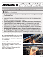
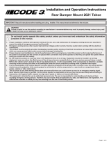
Step 1. Attach speaker to bracket using supplied hardware
NOTE: The speaker MUST be oriented with the speaker wires
exiting the bottom of the speaker. The exit holes for the wires
are also the drain holes. Failure to mount the speaker in this
orientation voids all warranties.
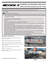
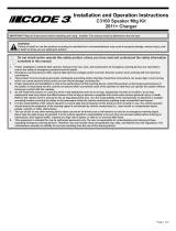
Step 2. Remove the headlight assembly (pull clip and screw).
Step 3. Attach Speaker and bracket assembly to frame rail with supplied hardware (holes may be under sticker).
Step 4. Connect Speaker leads to siren according to siren install manual.
Step 5. Reinstall headlight assembly.
Installation and Mounting:
WARNING!
Sirens produce loud sounds that may damage hearing.
• Wear hearing protection when testing
• Use siren only for emergency response
• Roll up windows when siren is operating
• Avoid exposure to the siren sound outside of vehicle
Figure 1
5/16”-18 Button Head Screw
& 5/16” Split Lock Washer
4x - #12 Phillips Pan Head
& 1/4” Inside Star Washer
Figure 2
Remove to take
out headlight
Figure 3
2X - 1/4” Type B Screw,
1/4” Split Lock Washer, &
1/4” Flat Washer
5/16”-18 Self Tapping Bolt,
5/16” Split Washer, & 5/16”
Flat Washer

Page 3 of 4
Notes:

Page 4 of 4
An ECCO SAFETY GROUP™ Brand
ECCOSAFETYGROUP.com
10986 North Warson Road, St. Louis, MO 63114 USA
Technical Service USA (314) 996-2800
CODE3ESG.com
Product Returns:
If a product must be returned for repair or replacement*, please contact our factory to obtain a Return Goods Authorization Number (RGA
number) before you ship the product to Code 3®, Inc. Write the RGA number clearly on the package near the mailing label. Be sure you use
sucient packing materials to avoid damage to the product being returned while in transit.
*Code 3®, Inc. reserves the right to repair or replace at its discretion. Code 3®, Inc. assumes no responsibility or liability for expenses incurred for the removal and /or reinstallation of products requiring
service and/or repair.; nor for the packaging, handling, and shipping: nor for the handling of products returned to sender after the service has been rendered.
Manufacturer Limited Warranty Policy:
Manufacturer warrants that on the date of purchase this product will conform to Manufacturer’s specications for this product (which are avail-
able from the Manufacturer upon request). This Limited Warranty extends for Sixty (60) months from the date of purchase.
DAMAGE TO PARTS OR PRODUCTS RESULTING FROM TAMPERING, ACCIDENT, ABUSE, MISUSE, NEGLIGENCE, UNAPPROVED MODIFICA-
TIONS, FIRE OR OTHER HAZARD; IMPROPER INSTALLATION OR OPERATION; OR NOT BEING MAINTAINED IN ACCORDANCE WITH THE
MAINTENANCE PROCEDURES SET FORTH IN MANUFACTURER’S INSTALLATION AND OPERATING INSTRUCTIONS VOIDS THIS LIMITED WAR-
RANTY.
Exclusion of Other Warranties:
MANUFACTURER MAKES NO OTHER WARRANTIES, EXPRESS OR IMPLIED. THE IMPLIED WARRANTIES FOR MERCHANTABILITY, QUALITY
OR FITNESS FOR A PARTICULAR PURPOSE, OR ARISING FROM A COURSE OF DEALING, USAGE OR TRADE PRACTICE ARE HEREBY EX-
CLUDED AND SHALL NOT APPLY TO THE PRODUCT AND ARE HEREBY DISCLAIMED, EXCEPT TO THE EXTENT PROHIBITED BY APPLICABLE
LAW. ORAL STATEMENTS OR REPRESENTATIONS ABOUT THE PRODUCT DO NOT CONSTITUTE WARRANTIES.
Remedies and Limitation of Liability:
MANUFACTURER’S SOLE LIABILITY AND BUYER’S EXCLUSIVE REMEDY IN CONTRACT, TORT (INCLUDING NEGLIGENCE), OR UNDER ANY
OTHER THEORY AGAINST MANUFACTURER REGARDING THE PRODUCT AND ITS USE SHALL BE, AT MANUFACTURER’S DISCRETION, THE
REPLACEMENT OR REPAIR OF THE PRODUCT, OR THE REFUND OF THE PURCHASE PRICE PAID BY BUYER FOR NON-CONFORMING PROD-
UCT. IN NO EVENT SHALL MANUFACTURER’S LIABILITY ARISING OUT OF THIS LIMITED WARRANTY OR ANY OTHER CLAIM RELATED TO
THE MANUFACTURER’S PRODUCTS EXCEED THE AMOUNT PAID FOR THE PRODUCT BY BUYER AT THE TIME OF THE ORIGINAL PURCHASE.
IN NO EVENT SHALL MANUFACTURER BE LIABLE FOR LOST PROFITS, THE COST OF SUBSTITUTE EQUIPMENT OR LABOR, PROPERTY
DAMAGE, OR OTHER SPECIAL, CONSEQUENTIAL, OR INCIDENTAL DAMAGES BASED UPON ANY CLAIM FOR BREACH OF CONTRACT, IM-
PROPER INSTALLATION, NEGLIGENCE, OR OTHER CLAIM, EVEN IF MANUFACTURER OR A MANUFACTURER’S REPRESENTATIVE HAS BEEN
ADVISED OF THE POSSIBILITY OF SUCH DAMAGES. MANUFACTURER SHALL HAVE NO FURTHER OBLIGATION OR LIABILITY WITH RESPECT
TO THE PRODUCT OR ITS SALE, OPERATION AND USE, AND MANUFACTURER NEITHER ASSUMES NOR AUTHORIZES THE ASSUMPTION OF
ANY OTHER OBLIGATION OR LIABILITY IN CONNECTION WITH SUCH PRODUCT.
This Limited Warranty denes specic legal rights. You may have other legal rights which vary from jurisdiction to jurisdiction. Some jurisdic-
tions do not allow the exclusion or limitation of incidental or consequential damages.
© 2007 Code 3, Inc. all rights reserved.
T16214 Rev. A
Warranty:

C3100 Speaker
Bracket Kit
2006 Chevy Impala
Installation
& Owners
Manual
WARNING
Sirens produce loud sounds that may damage hearing
• Wear hearing protection when testing
• Use siren only for emergency response
• Roll up windows when siren is operating
• Avoid exposure to the siren sound outside of vehicle
Read all instructions and warnings before installing and using this equipment.
INSTALLER: This manual must be delivered to the end user of this equipment.
IMPORTANT:

Sirens are an integral part of an effective audio/visual emer-
gency warning system. However, sirens are only short range
secondary warning devices. The use of a siren does not insure
that all drivers can or will observe or react to an emergency
warning signal, particularly at long distances or when either
vehicle is traveling at a high rate of speed. Sirens should only
be used in a combination with effective warning lights and
never relied upon as a sole warning signal. Never take the right
of way for granted. It is your responsibility to be sure you can
proceed safely before entering an intersection, driving against
traffic, or responding at a high rate of speed.
The effectiveness of this warning device is highly dependent
upon correct mounting and wiring. Read and follow the
manufacturer’s instructions before installing or using this
device. The vehicle operator should check the equipment daily
to insure that all features of the device operate correctly.
To be effective, sirens must produce high sound levels that
potentially can inflict hearing damage. Installers should be
warned to wear hearing protection, clear bystanders from the
area and not to operate the siren indoors during testing.
Vehicle operators and occupants should assess their exposure
to siren noise and determine what steps, such as consultation
with professionals or use of hearing protection should be
implemented to protect their hearing.
This equipment is intended for use by authorized personnel
only. It is the user’s responsibility to understand and obey all
laws regarding emergency warning devices. The user should
check all applicable city, state and federal laws and regulations.
Code 3, Inc., assumes no liability for any loss resulting from the
use of this warning device.
Proper installation is vital to the performance of the siren and
the safe operation of the emergency vehicle. It is important to
recognize that the operator of the emergency vehicle is under
psychological and physiological stress caused by the emer-
gency situation. The siren system should be installed in such a
manner as to: A) Not reduce the acoustical performance of the
system, B) Limit as much as practical the noise level in the
passenger compartment of the vehicle, C) Place the controls
within convenient reach of the operator so that he can operate
the system without losing eye contact with the roadway.
Emergency warning devices often require high electrical
voltages and/or currents. Properly protect and use caution
around live electrical connections. Grounding or shorting of
electrical connections can cause high current arcing, which can
cause personal injury and/or severe vehicle damage, including
fire.
PROPER INSTALLATION COMBINED WITH OPERATOR
TRAINING IN THE PROPER USE OF EMERGENCY WARN-
ING DEVICES IS ESSENTIAL TO INSURE THE SAFETY OF
EMERGENCY PERSONNEL AND THE PUBLIC.
WARNING!
SIREN PRODUCTS:
!

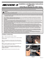
Installation:
Mount the speaker to the bracket
using the mounting hardware
supplied (Fig. 1).
WARNING! The speaker wires must
exit through the bottom of the speaker.
The speaker wire hole is also the
drainage hole. Improper mounting will
damage the driver and void the
warranty.
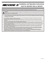
Remove drivers side headlamp
assembly. This is accomplished by
removing the screw and plastic clip.
Place speaker assembly in position
(see fig. 2) and mark holes for drilling.
Drill 2 holes (No.8 drill or 0.199"). Bolt
the speaker in place using the thread
cutting hardwarew provided.
Extend the BLUE (Positive) and WHITE
(Negative) speaker wires to the siren
amplifier and connect them as shown
in the amplifier’s instructions and test
the siren for proper operation.
Fig 2
Fig 1

PRODUCT RETURNS
If a product must be returned for repair or replacement*, please
contact our factory to obtain a Return Goods Authorization Number (RGA
number) before you ship the product to Code 3, write the RGA number
clearly on the package near the mailing label. Be sure you use sufficient
packing materials to avoid damage to the product being returned while in
transit.
*Code 3, Inc. reserves the right to repair or replace at its discretion. Code 3, Inc. assumes no
responsibility or liability for expenses incurred for the removal and /or reinstallation of products requiring
service and/or repair.; nor for the packaging, handling, and shipping: nor for the handling of products return to
sender after the service has been rendered.
Revision 0, 02/2006 - Instruction Book Part No. T08835
©2006, CODE 3, Inc. Printed in USA
Code 3 is a registered trademark of Code 3, Inc.
a subsidiary of Public Safety Equipment, Inc.
CODE 3, Inc.
10986 N. Warson Road
St. Louis, Missouri 63114-2029—USA
www.code3pse.com
WARRANTY
Code 3, Inc. emergency devices are tested and found to be operational
at the time of manufacture. Provided they are installed and operated in
accordance with manufacturer's recommendations, Code 3, Inc. guarantees
all parts and components except the lamps to a period of 1 year (unless
otherwise expressed) from the date of purchase or delivery, whichever is
later. Units demonstrated to be defective within the warranty period will be
repaired or replaced at the factory service center at no cost.
Use of lamp or other electrical load of a wattage higher than installed
or recommended by the factory, or use of inappropriate or inadequate wiring
or circuit protection causes this warranty to become void. Failure or
destruction of the product resulting from abuse or unusual use and/or
accidents is not covered by this warranty. Code 3, Inc. shall in no way be
liable for other damages including consequential, indirect or special damages
whether loss is due to negligence or breach of warranty.
CODE 3, INC. MAKES NO OTHER EXPRESS OR IMPLIED
WARRANTY INCLUDING, WITHOUT LIMITATION, WARRAN-
TIES OF FITNESS OR MERCHANTABILITY, WITH RESPECT
TO THIS PRODUCT.
NEED HELP? Call our Technical
Assistance Hotline - (314) 996-2800
/