Danfoss MBT Temperature Sensors User guide

Type
User guide
Safety Manual and Programmer Guide
PLUS+1® Compliant
PVED-CLS Hardware Function Blocks
www.danfoss.com
Revision history Table of revisions
Date Changed Rev
November 2018 First edition 0101
Safety Manual and Programmer Guide
PVED-CLS Hardware Function Blocks
2 |
©
Danfoss | November 2018 AQ00000254en-000101
Document Overview
Quality and Safety Considerations
Applicable Function Blocks for This Safety Manual............................................................................................................. 5
Safety Integrity Level.......................................................................................................................................................................6
Reference Manuals...........................................................................................................................................................................6
Obtaining Technical Literature and Reference Manuals...............................................................................................7
Obtaining Product Support..........................................................................................................................................................7
Common Features of the Function Blocks
All Blocks Have a Common Structure........................................................................................................................................8
All Blocks Have Inputs that Require Defined Data Types...................................................................................................9
All Blocks Have Companion Service Screens..........................................................................................................................9
Import Service Tool Pages from the PLUS+1
®
GUIDE Library Tab Manager........................................................10
Using Identical Blocks in the Same Application
Identical Function Blocks Need Different Namespace Values to Successfully Compile...................................... 12
Identical Service Tool Screens Need Different Signal Name Prefixes to be Usable...............................................12
Change Signal Name Prefixes with the Find and Replace Feature..............................................................................13
Switching Between Different Parameter Sets..................................................................................................................... 13
Fault of Input Signals....................................................................................................................................................................14
Status of Parameters.....................................................................................................................................................................14
Best Practices
Using the Same Parameter in Several Function Blocks....................................................................................................15
Controller Memory Consumption............................................................................................................................................15
Glossary
Abbreviations
Safety Manual and Programmer Guide
PVED-CLS Hardware Function Blocks
Contents
©
Danfoss | November 2018 AQ00000254en-000101 | 3
This manual provides information that is applicable to every function block of the PVED-CLS hardware
function block library.
You must read this Safety Manual and Programmer Guide before you read any user manual for a specific
PVED function block.
Safety Manual and Programmer Guide
PVED-CLS Hardware Function Blocks
Document Overview
4 |
©
Danfoss | November 2018 AQ00000254en-000101
You must know and follow appropriate safety standards and specifications when developing a product.
Fulfilling standards and legal requirements results in several development needs — documentation,
development processes, organizational structures, and so on. All these needs have the goal to ensure a
certain product quality and safety. Meeting these requirements also makes your product development
process transparent and traceable for others.
The following are some items to consider when developing your application:
Review your specification of requirements, design, code and tests with peers.
Document decisions, actions, specifications, designs and reviews.
Assign the different roles to members of your team, such as programmer, tester, review team, and so
on.
Ensure the tester is a different person than the programmer.
Test all required functions, including functions in machines operating at extremes, on the target
platform.
Test all the required functions, including extreme situations and worst case scenarios, on the target
platform.
Implement life cycle and change management.
Ensure your documentation is complete, comprehensive, and understandable.
These considerations are necessary as a minimum. You may have additional considerations for your
application.
Applicable Function Blocks for This Safety Manual
The content of this safety manual is valid for the following PVED-CLS Hardware Function Blocks
contained in the PVED_CLS_70316311v100.HWD.
W
Warning
Read this manual completely before programming your application.
Name Version
PVED_CLS_AUX_JOY 1.00
PVED_CLS_AUX_STW 1.00
PVED_CLS_GMC 1.00
PVED_CLS_GMS 1.00
PVED_CLS_MMI 1.00
PVED_CLS_STAT_Msg_0_OP 1.00
PVED_CLS_STAT_Msg_1 1.00
PVED_CLS_STAT_Msg_2 1.00
PVED_CLS_STAT_Msg_3 1.00
PVED_CLS_STAT_Msg_4 1.00
PVED_CLS_STAT_Msg_5 1.00
PVED_CLS_STAT_Msg_6 1.00
PVED_CLS_STAT_Msg_7 1.00
PVED_CLS_STAT_Msg_8 1.00
PVED_CLS_Str_Fdbk 1.00
PVED_CLS_STW 1.00
PVED_CLS_VSP 1.00
PVED_CLS_WAS 1.00
Safety Manual and Programmer Guide
PVED-CLS Hardware Function Blocks
Quality and Safety Considerations
©
Danfoss | November 2018 AQ00000254en-000101 | 5
Safety Integrity Level
The PVED-CLS Hardware Function Block Library is designed to meet SIL 2 in accordance with IEC 61508
Ed. 3.
The OEM/customer is responsible for the overall functional safety specification, safety integrity level
requirement, implementation and validation of their application. Detailed analysis, review and
documentation for compliance to ISO 13849 or ISO 25119 must be done by the designer or integrator of
the safety related system.
The OEM/customer must select an appropriate PLUS+1
®
controller for the application. This selection
depends on the identified target risk reduction required for the application.
The function blocks in the library are unit tested and suitable for direct integration into the OEM/
customer target PLUS+1
®
GUIDE application software. Each function block is designed for signal
conversion and not for performing any safety functions.
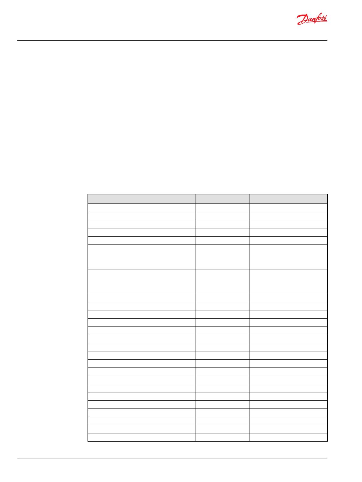
Reference Manuals
The documents described here can help you understand how to use PVED-CLS function blocks.
Title Type Identification number
PLUS+1®SC0XX-1XX Controller Family Technical Information L1415500, L1206334
PLUS+1®SC0XX-1XX Controller Family Safety Manual L1420375, L1228981
PLUS+1®Controller Family Technical Information 520L0719
PLUS+1®GUIDE Software User Manual Operation Manual 10100824
How to Install PLUS +1®GUIDE Upgrades Operation Manual 11078040
PVED-CLS Controller For Electrohydraulic Steering User Manual See Obtaining Technical Literature
and Reference Manuals for more
information about obtaining this
document.
PVED-CLS Controller For Electrohydraulic Steering Communication Protocol See Obtaining Technical Literature
and Reference Manuals for more
information about obtaining this
document.
PVED_CLS_Safety_ Manual_and_Programmer_Guide User Manual AQ00000254
PVED_CLS_AUX_JOY User Manual User Manual AQ00000255
PVED_CLS_AUX_STW User Manual User Manual AQ00000256
PVED_CLS_GMC User Manual User Manual AQ00000257
PVED_CLS_GMS User Manual User Manual AQ00000258
PVED_CLS_MMI User Manual User Manual AQ00000259
PVED_CLS_STAT_0_OP User Manual User Manual AQ00000260
PVED_CLS_STAT_1 User Manual User Manual AQ00000261
PVED_CLS_STAT_2 User Manual User Manual AQ00000262
PVED_CLS_STAT_3 User Manual User Manual AQ00000263
PVED_CLS_STAT_4 User Manual User Manual AQ00000264
PVED_CLS_STAT_5 User Manual User Manual AQ00000265
PVED_CLS_STAT_6 User Manual User Manual AQ00000266
PVED_CLS_STAT_7_User_Manual User Manual AQ00000267
PVED_CLS_STAT_8 User Manual User Manual AQ00000268
PVED_CLS_Str_Fdbk User Manual User Manual AQ00000269
PVED_CLS_STW User Manual User Manual AQ00000270
PVED_CLS_WAS User Manual User Manual AQ00000271
Safety Manual and Programmer Guide
PVED-CLS Hardware Function Blocks
Quality and Safety Considerations
6 |
©
Danfoss | November 2018 AQ00000254en-000101
Obtaining Technical Literature and Reference Manuals
You can find literature about Danfoss products online and in the PLUS+1
®
GUIDE tool.
Obtain online help for the PLUS+1
®
GUIDE tool by using the application's Help menu.
PVED-CLS documents are part of the PVED-CLS firmware release packages. You can download the
packages at: https://www.danfoss.com/en/products/steering/dps/steering-components-and-systems/
electrohydraulic-steering/pved-cls/#overview
Obtaining Product Support
You can find information about product support, product news, parts, and more at the link that follows.
https://www.danfoss.com/en/products/software/dps/plus1-software-services-support-and-training/plus1-
support-and-services
Safety Manual and Programmer Guide
PVED-CLS Hardware Function Blocks
Quality and Safety Considerations
©
Danfoss | November 2018 AQ00000254en-000101 | 7
Function blocks share some common features.
All function blocks have:
A common structure.
Inputs that require defined data types.
Companion PLUS+1
®
Service Tool screens
All Blocks Have a Common Structure
Function blocks share common features that provide the machine with feedback for its operation.
Item Description
1 Function block description. Describes the general purpose of the function block.
2 Note. General information about data types and the available checkpoints.
3 Parameter page. Contains default parameter values. Values can be changed or replaced with signals from the application via the Para Bus.
4 Logic page. Contains a function block’s operating logic. This is a locked page that you cannot enter.
5 Checkpoints page. Contains Advanced Checkpoints with Namespace components that can make all of a block’s input, output and internal
signals available to the PLUS+1
®
Service Tool. To disable these signals set a block’s Chkpt input to False before you compile your application.
6
Input signal description. Explanatory text that describes the input’s:
Purpose
Data type
Expected range
Unit
7
Output signal description. Explanatory text that describes the output’s:
Purpose
Data type
Expected range
Unit
Safety Manual and Programmer Guide
PVED-CLS Hardware Function Blocks
Common Features of the Function Blocks
8 |
©
Danfoss | November 2018 AQ00000254en-000101
All Blocks Have Inputs that Require Defined Data Types
To avoid compiler errors, use only the data type specified for an input.
These blocks do not allow autotyped inputs.
Item Description
1
The ErrCode input requires an input with a U8 data type.
2 If an incorrect data type is routed to the ErrCode input, then the compiler Error Message tab (with the error message generated by the
incorrect U32 data type) shows that a wrong type was chosen.
3 Compiler Error Message tab. The compilation does not finish.
All Blocks Have Companion Service Screens
All function blocks have P1D (PLUS+1 Diagnostic) files with companion Service Tool screens.
You can use these screens to simplify the task of creating PLUS+1
®
Service Tool screens for applications
that use PVED-CLS hardware function blocks. Refer to the PLUS+1 GUIDE Service Tool Design Manual
(Danfoss document number AQ00000160 for more information on how to create PLUS+1
®
Service Tool
screens.
The following figure shows the PLUS+1
®
Service Tool screen for a PVED-CLS function block. These screens
are typical of the PLUS+1
®
Service Tool screens supplied with function blocks.
You must set a function block’s Chkpt input to true to make a function block’s input and output signals
available to the PLUS+1
®
Service Tool program.
Safety Manual and Programmer Guide
PVED-CLS Hardware Function Blocks
Common Features of the Function Blocks
©
Danfoss | November 2018 AQ00000254en-000101 | 9
1. Right-click on Parameter Functions to open the dialog for importing service screens.
2. Select the service screen PFX file you want to import. In this figure, PVED_CLS_AUX_JOY_Msg.pfx is
selected.
3. The service screen is imported to the PLUS+1
®
Service Tool.
4. The service screen shows input, output and internal values to visualize the function block’s signal
flow. Input signals are located on the left side, output signals on the right side. In addition, the service
screen provides access to user-configurable operating parameters. They are always located in a
yellow panel.
5. Click Replace missing ECU in all log and parameter functions to replace the preset ECU “0,42 -
(Missing ECU)”.
Using the Replace missing ECU in all log and parameter functions feature is highly recommended
if service screens have been imported. Otherwise parameter pre-settings are lost. To use this feature,
make sure your ECU is connected to the Service Tool.
6. Select your ECU (here: 0,2 - WT) which replaces the missing ECU.
Import Service Tool Pages from the PLUS+1
®
GUIDE Library Tab Manager
In PLUS+1
®
GUIDE versions 8.1 and later, service screens (PFX files) and other documents can be stored in
libraries.
In the PVED-CLS Hardware Function Block Library for each module, the module itself (SCS file), the User
Manual, the Safety Manual and Programmer Guide and the service screen are stored under the
corresponding module – all in one place. Because of this change, use the following steps to import PLUS
+1
®
Service Tool pages to the PLUS+1
®
Service Tool.
Safety Manual and Programmer Guide
PVED-CLS Hardware Function Blocks
Common Features of the Function Blocks
10 |
©
Danfoss | November 2018 AQ00000254en-000101
1. Browse to the module of interest.
2. Right-click the service screen of the module.
3. Select Save to, then select the location and save the file.
4. Open the PLUS+1
®
Service Tool.
5. Continue as described in the topic All Blocks Have Companion Service Screens.
Safety Manual and Programmer Guide
PVED-CLS Hardware Function Blocks
Common Features of the Function Blocks
©
Danfoss | November 2018 AQ00000254en-000101 | 11
To use identical function blocks in the same application, perform the following steps.
1. Change the function block’s namespace values.
2. Change the prefixes of the names of the signals displayed in the function block’s companion PLUS+1
®
Service Tool screens if you want to use these screens.
Identical Function Blocks Need Different Namespace Values to Successfully Compile
If you use the same function block more than once in an application, you must change each function
block’s namespace value to avoid compiler errors.
All function blocks contain Advanced Checkpoint with Namespace components that enable the PLUS+1
®
Service Tool to read block input and output values.
Some function blocks contain non-volatile memory components that store function block operating
parameters.
Both these components use memory names (“aliases”) to allocate memory. Identical memory names
cause compiler errors.
The namespace value adds a unique prefix to each component name to avoid errors. Keep each
namespace value short to save controller memory.
Identical Service Tool Screens Need Different Signal Name Prefixes to be Usable
If you use the same work function block more than once in an application, you must change the signal
name prefixes used in the companion PLUS+1
®
Service Tool screens to make the screens usable.
The input and output signals for blocks all have namespace prefixes. Danfoss configured the companion
PLUS+1
®
Service Tool screens to read signal names with these prefixes.
You must set a function block’s Chkpt input to true (which is the default value) to make the function
block’s input and output signals available to the PLUS+1
®
Service Tool program’s companion screens.
The following figure shows how a function block’s namespace value prefixes a signal name from the
function block.
Safety Manual and Programmer Guide
PVED-CLS Hardware Function Blocks
Using Identical Blocks in the Same Application
12 |
©
Danfoss | November 2018 AQ00000254en-000101
Item Description
1 The namespace value for this block is now PVED_CLS_STW. All input and output signals from this function block now have a
PVED_CLS_STW_ prefix.
2 The PVED_CLS_STW_CP_Angle signal as it appears in the Design Screen (Advanced) window of the PLUS+1
®
Service Tool.
3 The Properties window that selects the PVED_CLS_STW_CP_Angle signal for display on the Engine Control Basic service screen.
Change Signal Name Prefixes with the Find and Replace Feature
You can simplify how you change name prefixes by using the Find and Replace feature.
Use the Find and Replace feature of the PLUS+1
®
Service Tool to change the namespace prefixes in PLUS
+1
®
Service Tool signal names.
Refer to the PLUS+1 GUIDE Service Tool Design Manual (Danfoss part L1320837) for more information
about the Find and Replace feature.
Switching Between Different Parameter Sets
Schedule changes to parameter sets while the machine is in a safe state.
W
Warning
Do not change parameters while the machine is driving. Changing parameters while the machine is
driving could result in a dangerous situation. Before changing parameters, ensure that the machine is in a
safe state (for example, with standstill and neutral conditions) to prevent any harm to operators and
bystanders.
Safety Manual and Programmer Guide
PVED-CLS Hardware Function Blocks
Using Identical Blocks in the Same Application
©
Danfoss | November 2018 AQ00000254en-000101 | 13
Fault of Input Signals
Input signals that do not use the full range of their data type are checked to determine if they are in the
allowed range.
If they are outside their range they are clamped to fit into their range. The Fault output displays a fault
code.
Value Fault
0x0000 OK, no fault.
0x8001 Input value too low.
0x8002 Input value too high.
Status of Parameters
A status output, rather than a fault output, is given for parameter faults where parameters are out of
range or where parameters are lacking order (for example, Src_Addr > 253).
If a parameter is outside an allowed range, the parameter is clamped to fit into the allowed range. The
allowed range is listed for every parameter in the individual function block’s user manual. The upper and
lower limit are always included as valid values.
Value Fault
0x0000 OK
0x8008 At least one parameter is out of its defined range or in the wrong order.
Safety Manual and Programmer Guide
PVED-CLS Hardware Function Blocks
Using Identical Blocks in the Same Application
14 |
©
Danfoss | November 2018 AQ00000254en-000101
The following guidelines can help achieve good outcomes when using the same parameter in several
function blocks and when managing controller memory consumption.
Using the Same Parameter in Several Function Blocks
Sometimes the same parameter is needed in several function blocks.
Because such a parameter is placed independently in each function block where it is used, it has multiple
definitions without any automated alignment.
Recommendations for handling this are:
Remove the duplicated parameters and connect them to one common parameter block, so that the
value of the parameter is controlled from one central point.
Update the service screens.
Controller Memory Consumption
Every function block included in your application uses a certain amount of the controller’s memory.
Also, every checkpoint consumes a bit of memory. Depending on the amount of the controller’s memory
and the complexity of your application you might run out of memory.
If the controller runs out of memory, you can first remove unnecessary checkpoints to regain memory.
There are two ways to remove the function block’s checkpoints.
Delete single checkpoints inside the Checkpoints page on the second level.
Remove all function block’s checkpoints from the compiled code. This can be achieved easily by
changing the Chkpt input of the Checkpoints page from True (T) to False (F). After you recompile the
code, none of the function block’s checkpoints are included.
To integrate the checkpoints again, set the Chkpt input back to True (T) and recompile the code.
Be aware that some checkpoints include Status and Fault information. If you deactivate or delete them
you no longer see them on the service screen.
Safety Manual and Programmer Guide
PVED-CLS Hardware Function Blocks
Best Practices
©
Danfoss | November 2018 AQ00000254en-000101 | 15
Terms and acronyms about safety are defined.
ECU Electronic Control Unit
Fail-Safe State Functional safety term. State where the safety output is de-energized.
HWD The file that defines how the GUIDE application is connected to the controller hardware. The
abbreviation stands for Hardware Description.
IEC International Electrotechnical Commission
OEM Original Equipment Manufacturer
P1D The file format extension used by the PLUS+1 Service Tool. The abbreviation stands for PLUS+1
®
Diagnostic.
PVED-CLS Valve controller and actuator. The abbreviation stands for Proportional Valve Electronic Digital
– Closed Loop Safety.
SCS A file that contains graphical code used with the PLUS+1
®
GUIDE application.
SIL Functional Safety Term. Safety Integrity Level.
Safety Manual and Programmer Guide
PVED-CLS Hardware Function Blocks
Glossary
16 |
©
Danfoss | November 2018 AQ00000254en-000101
Abbreviations used in the PVED-CLS function block user manuals are described.
Abbreviation Meaning
AUX JOY Auxiliary Joystick
AUX STW Auxiliary Steering Wheel
CLS Closed Loop Safety
GMC Guidance System Command
GMS Guidance Machine Status
MMI Man Machine Interface
PVED CLS Proportional Valve Electronic Digital Closed Loop Safety
STAT MSG OP Status Message Operation
STAT MSG Status Message
Str Fdbk Steering Feedback
STW Steering Wheel
VSP Vehicle Speed
WAS Wheel Angle Sensor
Safety Manual and Programmer Guide
PVED-CLS Hardware Function Blocks
Abbreviations
©
Danfoss | November 2018 AQ00000254en-000101 | 17
Safety Manual and Programmer Guide
PVED-CLS Hardware Function Blocks
18 |
©
Danfoss | November 2018 AQ00000254en-000101
Safety Manual and Programmer Guide
PVED-CLS Hardware Function Blocks
©
Danfoss | November 2018 AQ00000254en-000101 | 19
Danfoss Power Solutions is a global manufacturer and supplier of high-quality hydraulic and
electric components. We specialize in providing state-of-the-art technology and solutions
that excel in the harsh operating conditions of the mobile off-highway market as well as the
marine sector. Building on our extensive applications expertise, we work closely with you to
ensure exceptional performance for a broad range of applications. We help you and other
customers around the world speed up system development, reduce costs and bring vehicles
and vessels to market faster.
Danfoss Power Solutions – your strongest partner in mobile hydraulics and mobile
electrification.
Go to www.danfoss.com for further product information.
We offer you expert worldwide support for ensuring the best possible solutions for
outstanding performance. And with an extensive network of Global Service Partners, we also
provide you with comprehensive global service for all of our components.
Local address:
Danfoss
Power Solutions GmbH & Co. OHG
Krokamp 35
D-24539 Neumünster, Germany
Phone: +49 4321 871 0
Danfoss
Power Solutions ApS
Nordborgvej 81
DK-6430 Nordborg, Denmark
Phone: +45 7488 2222
Danfoss
Power Solutions (US) Company
2800 East 13th Street
Ames, IA 50010, USA
Phone: +1 515 239 6000
Danfoss
Power Solutions Trading
(Shanghai) Co., Ltd.
Building #22, No. 1000 Jin Hai Rd
Jin Qiao, Pudong New District
Shanghai, China 201206
Phone: +86 21 3418 5200
Danfoss can accept no responsibility for possible errors in catalogues, brochures and other printed material. Danfoss reserves the right to alter its products without notice. This also applies to products
already on order provided that such alterations can be made without subsequent changes being necessary in specifications already agreed.
All trademarks in this material are property of the respective companies. Danfoss and the Danfoss logotype are trademarks of Danfoss A/S. All rights reserved.
©
Danfoss | November 2018 AQ00000254en-000101
Products we offer:
DCV directional control
valves
Electric converters
Electric machines
Electric motors
Hydrostatic motors
Hydrostatic pumps
Orbital motors
PLUS+1
®
controllers
PLUS+1
®
displays
PLUS+1
®
joysticks and
pedals
PLUS+1
®
operator
interfaces
PLUS+1
®
sensors
PLUS+1
®
software
PLUS+1
®
software services,
support and training
Position controls and
sensors
PVG proportional valves
Steering components and
systems
Telematics
Comatrol
www.comatrol.com
Turolla
www.turollaocg.com
Hydro-Gear
www.hydro-gear.com
Daikin-Sauer-Danfoss
www.daikin-sauer-danfoss.com
  • Page 1 1
  • Page 2 2
  • Page 3 3
  • Page 4 4
  • Page 5 5
  • Page 6 6
  • Page 7 7
  • Page 8 8
  • Page 9 9
  • Page 10 10
  • Page 11 11
  • Page 12 12
  • Page 13 13
  • Page 14 14
  • Page 15 15
  • Page 16 16
  • Page 17 17
  • Page 18 18
  • Page 19 19
  • Page 20 20

Danfoss MBT Temperature Sensors User guide

Type
User guide

Ask a question and I''ll find the answer in the document

Finding information in a document is now easier with AI