Page is loading ...

INSTALL INSTRUCTIONS
Applicaon : 2020 Jeep Gladiator JT
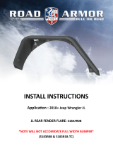
JT REAR FENDER FLARE: 520AFR0B

2020+ JEEP JT REAR FENDER FLARES Page ( 2 of 6)
www.ROADARMOR.com
INSTALL INSTRUCTIONS
SAFETY FIRST!
• FOLLOW ALL INSTRUCTIONS, YOUR SAFETY AND THE SAFETY OF OTHERS IS MOST IMPORTANT.
• WEAR APPROPRIATE EYE PROTECTION AND EXERCISE CAUTION WHEN DRILLING / CUTTING
REQUIRED TOOLS
INCLUDED HARDWARE
I WARNING
Read the instrucons completely before beginning installaon. Before ghtening bolts,
drilling or cung where required, check to make sure there are no obstrucons such as
brake, fuel or electrical lines which may be damaged. Also keep in mind this is an aer-
market product and MAY require minor shimming and/or trimming, reaming, etc. for
proper t. Road Armor is not responsible for any damages to vehicle.
IMPORTANT NOTICE
• Be sure to inspect and test t your product to ensure proper tment before having it coated, painted, bed
lined, etc.
• Road Armor will not be responsible for the cost of coang your unit if any problems with t or nish are not
Metric and SAE Socket Sets and Wrenches
Drill & Unibit & 17/32” Drill Bit
(6) 5/16”x1” Carriage Bolts
(30) 5/16”x1” Buon-Head Bolts
(10) 5/16” Flange Nuts
(26) 5/16” U-Nut
(6) 5/16” Push Retainer Washers
162” Rubber Edge Trim
(1) PSG FENDER FLARE
(1) DVR FENDER FLARE

2020+ JEEP JT REAR FENDER FLARES Page ( 3 of 6)
www.ROADARMOR.com
INSTALL INSTRUCTIONS
1 Remove 3 bolts and 3 plasc push clips from each inner wheel well.
NOTE Factory inner liners will no longer secure to fender well. RA Liners Recommended (520LFR0Z )
2 Remove rear fender assembly by rmly pulling on one end of fender unl all 12 clips “pop o”.
3
1 2
3 Drill-out 12 exisng holes to 3/8” as shown below. (All)
4 If installing fenders without Inner Liners (520LFR0Z); install 5/16” U-nuts onto fender seam. (BLUE)
5 Remove harness support bracket from Dvr. Side rear frame rail as shown: (When installing RA-liners)
4
5

2020+ JEEP JT REAR FENDER FLARES Page ( 4 of 6)
www.ROADARMOR.com
INSTALL INSTRUCTIONS
8 If installing without inner fender liners place fender onto bed seam by aligning 5/16” carriage bolts.
Loosely install pinch seam bolts using 7 - 5/16” buon-head bolts; (BLUE Arrows)
followed by: 6 - 5/16” buon-head bolts & U-nuts as shown below; (Dummy Bolts) (GREEN Arrows)
followed by: 5 - 5/16” ange nuts onto carriage. (& bolts buon-head bolts) (RED)
*TIGHTEN ALL HARDWARE AT THIS TIME*
6 Assembly REAR FENDER using 3 - 5/16” CARRIAGE BOLTS and PUSH RETAINER WASHERS. (BLUE)
7 Install EDGE TRIM along main fender edge to protect body. (Insert at side of trim on boom.)
7
6
8
FINISHED!

2020+ JEEP JT REAR FENDER FLARES Page ( 5 of 6)
www.ROADARMOR.com
INSTALL INSTRUCTIONS
8 If installing RA Fenders with Inner Liners (520LFR0Z), refer to steps below.
Assemble fender liners using 9 - 5/16” buon-head bolts and ange nuts; (GREEN)
NOTE: TRIM CIRCLED BOLT FLUSH WITH NUT FOR CLEARANCE (
followed by 11 - 5/16” U-nuts as shown below: (RED)
Install RA - Logo backing plate using #10 hardware. (ORANGE)
9 Install 2 - 5/16” U-nuts onto rear pinch seam as shown below.
10 Install 3 OEM 6mm bolts through Inner fender liners and lower bed seam. (RED)
8
10
9

2020+ JEEP JT REAR FENDER FLARES Page ( 6 of 6)
www.ROADARMOR.com
INSTALL INSTRUCTIONS
FINISHED!
11
11 Install fenders onto bed seam by aligning 5/16” carriage bolts.
Loosely install: 7 - 5/16” buon-head bolts through pinch seam
and into 5/16” U-nuts, on inner liners; (RED Arrows)
followed by: 6 - 5/16” buon-head bolts through fender and into
5/16” U-nuts, on inner liners; (Orangle Arrows)
followed by: 2 - 5/16” buon-head bolts & ange nuts at front
boom edge of fenders, as shown below; (GREEN Arrows)
followed by: 3 - 5/16” ange nuts onto carriage bolts. (BLUE)
12 Push EDGE TRIM against body for nished look without “gapping”.
13 Tighten all 5/16” HARDWARE at this me.
12
/

