Page is loading ...

AXL Series
INSTALLATION INSTRUCTIONS
INSTALLATION INSTRUCTIONS
800.533.3948 • www.barronltg.com
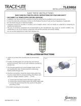
Knuckle Mount 15W, 30W, 50W
1. Feed wire lead from 1/2” NPT knuckle into weatherproof box cover / post top fitter, whichever applies, then securely
seat knuckle into box cover / post top fitter.
2. Electrical connections should be made inside an approved junction box. Cap all unused leads to prevent shorting.
This fixture auto adjust for voltages between 120VAC - 277VAC.
a. Connect the line fixture lead to the black supply lead.
b. Connect the common fixture lead to the white supply lead
c. Connect the ground lead form the service to the green grounding screw.
3. Use approved connectors to connect fixture leads to supply leads and make wire splices inside junction box.
4. To adjust fixture angle loosen screw on the center of the knuckle, adjust to desired position and retighten screw.
IMPORTANT
To weather-proof your outdoor installation, be sure to seal all holes in fixture housing.
(Mounting, conduit, plugs, and photo controls, etc) with silicone sealant.
20070103 REV 3 - 10/17
New image
IMPORTANT SAFEGUARDS
READ AND FOLLOW ALL SAFETY INSTRUCTIONS.
When using electrical equipment, basic safety precautions should always be followed including the following:
• DISCONNECT AC POWER SUPPLY BEFORE SERVICING.
• Installation and servicing of this equipment should be performed by qualified service personnel only.
• Ensure the electricity connections conform to the National Electrical Code and local regulations if applicable.
• Do not mount near gas or electrical heaters.
• Equipment should be mounted in locations and at heights where it will not readily be subjected to tampering by
unauthorized personnel.
• The use of accessory equipment not recommended by the manufacturer may cause an unsafe condition. Any
modification or use of non-original components will void the warranty and product liability.
• Do not use this equipment for other than intended use.
SAVE THESE INSTRUCTIONS!

AXL Series
INSTALLATION INSTRUCTIONS
800.533.3948 • www.barronltg.com
Trunnion and Yoke Mount
Yoke Dimensions 15W, 30W and 50W
Trunnion Dimensions 80W, 100W, 150W, 230W, and 300W
Yoke or Trunnion mounting directions
1. Mount fixture’s bracket to surface using expansion bolts or appropriate hardware (not supplied).
2. Allow proper cord length to ensure adjusting angle unhindered.
3. Use supplied 2’ cord installed on fixture to power the unit.
4. Electrical connections should be made inside an approved junction box. Fixture auto adjust for voltages between
120VAC-277VAC.
a. Connect the line fixture lead to the black supply lead.
b. Connect the common fixture lead to the white supply lead
c. Connect the ground lead form the service to the green grounding screw.
5. Use approved connectors to connect fixture leads to supply leads and make wire splices inside junction box.
6. Set desired fixture angle by loosening positioning screws and rotating the Yoke or Trunnion bracket to desired
angle, then re-tighten positioning screws.
20070103 REV 3 - 10/17
9”
4 3/8”
7/8” Ø
1”
7”
3 1/2”
4 7/8”
2 1/2”
2”
4 1/2”
1 3/8”
3/4”
1 3/8”
2 1/4”
7/8” Ø
7/8” Ø
7/8” Ø
1 3/8”
1 3/8”
1”
Fig. 1 Fig. 2 Fig. 3
Fig. 4

AXL Series
INSTALLATION INSTRUCTIONS
800.533.3948 • www.barronltg.com
20070103 REV 3 - 10/17
Slipfitter Mount
Arm Mount
If fixture and slipfitter are separate assemble
together as following illustration
Adjust fixture orientation by loosening
bolt, then retighten.
Use a post 2.36” diameter for mounting.
Secure to pole using appropriate
hardware.
If the lighting fixture and Arm are separated,
assemble the lighting fixture and Arm first.
Secure arm to post using approprate
screws
Dimming Driver Illustrations
Dimming available on the AXL100W,150W, 230W and 300W models.
Installation of the dimming wires should be performed by a qualified electrician according to local
electrical codes to preserve the IP65 Rating on the fixtures.
Models: 100W and 150W
Models: 230W and 300W
LED DRIVER
LED DRIVER
Dimming input
1-10VDC
Dimming input
1-10VDC
Output VDC
Output VDC
LED dimming
device
LED dimming
device
LED
LED
Dim+
Dim-
Input VAC
Input VAC
Dim+
Dim-
AC L (BLK)
INPUT
AC N (WHT)
(GRN)
VAUX/12V(BK/WH)
Dim+ (PUR)
Dim-(GRY)
V+(RED)
OUTPUT
V-(BLU)
AC L (BRN)
INPUT
AC N (BLU)
(GRN/YELO)
Dim+ (BLU)
Dim- (WHT)
V+(RED)
OUTPUT
V-(BLK)
L
N
G
L
N
G
/