Page is loading ...

INSTALLATION INSTRUCTIONS
800.533.3948 • www.barronltg.com
1
IMPORTANT SAFEGUARDS
READ AND FOLLOW ALL SAFETY INSTRUCTIONS.
When using electrical equipment, basic safety precautions should always be followed including the following:
• DISCONNECT AC POWER SUPPLY BEFORE SERVICING.
• Installation and servicing of this equipment should be performed by qualified service personnel only.
• Ensure that the electrical wiring conforms to the National Electrical Code NEC® and local regulations if applicable.
• Do not mount near gas or electrical heaters.
• Equipment should be mounted in locations and at heights where it will not be readily subjected to tampering by
unauthorized personnel.
• The use of accessory equipment not recommended by the manufacturer may cause an unsafe condition.
• Any modification or use of non-original components will void the warranty and product liability.
• Do not use this equipment for other than intended use.
SAVE THESE INSTRUCTIONS!
20070135 REV 4 - 02/19
R A
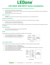
x
3.46in
6.96in
1.26in
1.26in
Ø 0.55in
0.98in
0.55in
Arm Mount - Drilling pattern
Pole Mount Arm
1. Remove the side plate from the arm. Skip to step 3
if mounting onto the square pole.
2. Attach round pole mounting plate onto the arm.
3. Route the cord through the arm, attach the fixture and
then tighten bottom screws.
4. Slightly pull the wires to make sure the hole on the
arm is sealed with a silicon gasket.
5. Make wiring connections inside arm. Refer to the
Wiring section.
6. Replace side plate ensuring the gasket is seated
correctly and fasten with screws.
Fig. 1

Slip-fitter
1. Route the cord through the slip-fitter, attach the fixture,
then tighten the bottom screws.
2. Remove the cover and adjust the slip-fitter to the
desired angle.
3. Make wiring connections. Refer to the Wiring section.
4. Install the slip-fitter on the 2” (2 3/8” O.D.) pole and
secure it with screws.
Wall Mount
1. Remove the side plate by loosening the screws.
2. Secure the backplate to the arm with the screws
provided.
3. Mark the desired location using the metal template
provided and drill holes to secure the arm to the wall
with appropriate anchors (not provided).
4. Route the cord through the arm, attach the fixture and
then tighten bottom screws.
5. Make wiring connections inside arm. Refer to the
Wiring section.
6. Replace side plate ensuring the gasket is seated
correctly and fasten with screws.
Trunnion Mount
1. Route the cord through the trunnion mount, attach the
fixture, then tighten the bottom screws.
2. Mark the desired mounting location and drill holes to secure
the trunnion to the desired surface with appropriate anchors
(not provided).
3. Make wiring connections. Refer to the Wiring section.
Wiring
Make AC power connections as follows:
Black - Line
White - Neutral
Green/Yellow Green - Ground
Dimming leads available in the 150W, 200W and 300W
models. A shielded 5 conductor line cord is provided for
convenience of installation, but not connected to the driver's
dimming leads. Connections inside housing at the driver and
at control device to be made as follows:
Purple - DIM+
Gray - DIM-
Note: This fixture auto adjusts for voltages from 120-277V or 347-480V driver. Cap all unused leads to prevent shorting.
IMPORTANT: Weather-proof your outdoor installation, be sure to seal all holes in fixture housing. (Mounting, conduit,
plugs, sensors and photocontrols, etc.) with silicone sealant.
Fig. 3
INSTALLATION INSTRUCTIONS
800.533.3948 • www.barronltg.com
2
20070135 REV 4 - 02/19
R A
x
Fig. 2
2 3/8”O.D
Pole size
/