Page is loading ...

* This chart is based on 1 set connected to the same wire run from the power
source.
* When installing 2 or more sets on one wire, the max length is obtained by
dividing the max wire length listed above by the number of sets installed.
6 WIRING
Read the following prior to installing,
wiring and regular maintenance.
2 INSTALLATION CONSIDERATIONS
The NR60AQM/120AQM/200AQM are quad photoelectric detectors designed to activate an alarm output upon the detection of intruder through 4 pulsed infrared
beams .
For stable operation, the NR60AQM/120AQM/200AQM are equipped with the following features.
- 100 Times Sensitivity Allowance
Stable operation is maintained even if 99% of beam energy is lost by rain, fog, frost, etc.
- Quad Beam Detection (AND/OR GATE Selectable)
AND GATE : All four beams need to be blocked simultaneously to trigger an alarm, resulting less false alarms caused by birds and other small animals.
OR GATE : Eather of Upper Two Beams or Lower Two Beams need to be blocked, resulting the detection of crawl through on the ground.
- Beam Power Control
This function allows selection of the appropriate beam intensity relative to the detection range to minimize the risk of reflection on the nearby walls and cross-taking
with other detectors.
- Beam Interruption Time Control
This feature can be used to change the beam interruption time to best fit the application.
- Stackable
The selectable beams up to 8 kinds can be used and it can allow to stack NRAQM up to 4 units for the high density beam barrier.
1 GENERAL DESCRIPTION
4 COMPONENTS
Make sure the following components are included in the package.
3 SUPPLIED PARTS
4-2-2 SHIN-MIYAKODA, KITAKU, HAMAMATSU, SHIZUOKA 431-2103 JAPAN
PHONE: +81-53-428-4116 FAX: +81-53-428-4119
PHOTOELECTRIC BEAM DETECTOR
NR60AQM :200ft./ 60m Range
NR120AQM:400ft./120m Range
NR200AQM:660ft./200m Range
INSTALLATION INSTRUCTIONS
We appreciate your purchase of ATSUMI PHOTOELECTRIC DETECTORS.
Please read the following installation instructions carefully for appropriate use of
the product.
CAUTION WARNING
DO NOT INSTALL THE UNIT
(1) where trees, plants, of falling leaves will block
the beams.
(2) where intense source of light, sunlight will be
reflected, directly into the receiver optics.
A external light incoming within ±3° angle of
each receiver axis may cause false alarms.
(3) where on movable surfaces.
(4) where subject to foul water or salt water.
(5) where over the max range on each model.
(6) where subject to strong electrical noise or RFI.
(7) where subject to strong vibration or impact.
(8) where subject to corrosive or explosive gas.
AVOID
(1) extreme temperature and humidity.
(2) magnets or any magnetized material.
(3) running power and output wires near high
voltage power sources.
(4) the beam interference between other units
when multiple units are installed as this beam
spread angle is 1.4 degree.
IMPORTANT
(1) Face upper/lower optical modules on the
transmitter and receiver towards each other.
(2) Be sure of the beam in alignment optical
modules can be adjusted within ±90°
horizontally and ±10° vertically.
Do not perform installation and wiring when it
thunders.
Do not supply power until all wiring is completed.
Keep power between 10.5~28 VDC anytime.
Do not disassemble or modify the unit.
Symbol Meaning
WARNING
CAUTION
Indicate that incorrect operation causes significant danger of accident resulting in
death or serious injury to the user.
Indicate that incorrect operation causes possibility of injury to the user or damage to
the unit.
8
8
8
2
Transmitter, Receiver
Installation Instructions
U-clamp
Mounting Plate
2
1
4
4
PARTS PCS
Clamping Screw (short 4×8mm)
Clamping Screw (long 4×25mm)
Chassis Mounting Screw (5×16mm)
High Density Connection Cables 2P
PARTS PCS
CHASSIS DETECTOR COVER
CHASSIS
MOUNTING
HOLE
UNIT MOUNTING
SCREW
WIRE HOLE
WIRE HOLE
LENS (UPPER)
SCOPE (UPPER)
TERMINALS
VERTICAL ADJUSTMENT
SCREW (UPPER)
HORIZONTAL ADJUSTMENT
SCREW (UPPER)
OPERATION PART
HORIZONTAL ADJUSTMENT
SCREW (LOWER)
VERTICAL ADJUSTMENT
SCREW (LOWER)
LENS (LOWER)
SCOPE (LOWER)
COVER MOUNTING
SCREW
CHASSIS
MOUNTING
HOLE
Transmitter has 5 terminals.
Receiver has 9 terminals.
OPERATION PART ON
TRANSMITTER
OPERATION PART ON
RECEIVER
POWER
E+ E- COM NC
POWER
1 2 3 4
ON
400
200
INDOOR 120
OUTDOOR 60
200
100
360
180
260
130
320
160
BEAM POWER
CONTROL(m)
TAMPER SYNCHRO
FUNCTIONNo. OFF ON
A BGROUP1
2 3M 1
ON ON2 OFF OFF
OFF ON3
4
OFF ON
POWER LED
DIP SWITCH
BEAM POWER
CONTROL
ALARM LED
EDC LED
LEVEL LED
DIP SWITCH
SENSITIVITY VOLUME
(INTERRUPTION TIME)
ALIGNMENT CHECK
TERMINALS
HIGH DENSITY
CONNECTION
Transmitter
A
B
C
Receiver
0.7°
The beam spread angle is ±0.7° .
Refer to the right table and the
diagrams below to determine the
installation conditions.
5 BEAM SPREAD
Spread (C)Distance (A)
20m
80m
60m
40m
Spread (B)
0.5m
140m
120m
100m
3.5m
3.0m
2.5m
200m
180m
160m
5.0m
4.5m
4.0m
2.0m
1.5m
1.0m
0.8m
3.7m
3.2m
2.7m
2.2m
4.7m
5.2m
4.2m
1.8m
1.3m
6.1 TERMINALS
8 FEATURES
8.1 SELECTABLE BEAMS
6.3 EXAMPLES
TRANSMITTER RECEIVER
Tamper Output (1b)
30VDC 0.1A
POWER (non-polarized)
10.5 - 28.0VDC
Tamper Output (1b)
30VDC 0.1A
SYNCHRO
POWER (non-polarized)
10.5 - 28.0VDC
ALARM Output (1c)
30VDC 0.2A
EDC Output (1b)
30VDC 0.2A
6.2 WIRING LENGTH (MAX ONE WAY LENGTH)
770
1,500
2,740
4,820
24VDC
80
160
300
530
12VDC
790
1,550
2,830
4,980
24VDC
80
170
310
550
12VDC
820
1,600
2,930
5,150
24VDC
90
170
320
570
12VDC
AWG22
AWG19
AWG17
AWG14
WIRE
GAUGE
NR60AQM NR120AQM NR200AQM
MAXIMUM DISTANCE (m)
1 SET
POWER
output
ALARM
input (NC)
Control Panel
Receiver Transmitter
2 SET
Receiver Transmitter Receiver Transmitter
POWER
output
ALARM
input (NC)
Control Panel
Note: * Do not supply power until all wiring is completed.
* Power is to be provided by a UL Listed burglar alarm power supply or
burglar alarm control panel.
* Refer to the National Electrical Code, NFPA70.
* This system should be tested at least once a week to ensure proper
function.
* Don’t wire aerial.
* Use pipes for outdoor wiring.
7 MOUNTING
- Choose an appropriate mounting location for the system. Install the poles with a clear line-of-sight
between the transmitter and the receiver.
- Loosen the transmitter’s cover mounting screw and remove the cover.
- Loosen the 2 unit mounting screws and remove the chassis by sliding it down against the unit.
- Attach the mounting plates to the chassis with the clamping screws (short) (see FIGURE 1).
- Firmly attach the chassis to the poles with the U-clamps and the screws (long) (see FIGURE 2).
Make sure the transmitter is mounted in direct line-of-sight with the receiver.
- Route wiring through the chassis wire hole, leaving enough wire to access the transmitter’s terminal
strip.
- Route wiring through the transmitter’s wire hole.
- Slide the transmitter onto the chassis. Tighten with the unit mounting screws.
- Repeat this mounting process for the receiver. Make sure it is mounted in direct line-of-sight with
the transmitter.
- Wire to the terminal strips. (Refer to the 6. WIRING)
- Keep more than 10mm space around the chassis as this detector is bigger than it.
- Use the knockout at the bottom of this detector for the surface wiring.
7.1 POLE MOUNTING
- Loosen the transmitter’s cover mounting screw and remove the cover.
- Loosen the 2 unit mounting screws and remove the chassis by sliding it down against the unit.
- Route wiring through the wire hole of the chassis. Leave enough wire to access the transmitter’s
terminal strip.
- Mount the chassis to the mounting surface with the chassis mounting screws.
- Route wiring through the wire hole of the transmitter. If surface mounting is used, knock-out the
thin-wall wire hole at the bottom of the transmitter.
- Reattach the transmitter to the chassis.
- Repeat this mounting procedure for the receiver. Make sure it is mounted in direct line-of-sight with
the transmitter.
- Wire to the terminal strips. (Refer to the 6. WIRING)
7.2 WALL MOUNTING
Back-to-back
Pole Mounting
Pole Diameter
38.0 - 42.7mm
Mounting Plate
Clamping
Screw
(short)
U-clamp
Clamping
Screw
(long)
FIGURE 1
FIGURE 2
Chassis
Chassis
Mounting
Screws
(included)
Wire Hole
Knockout
Unit Mounting
Screws
Crosstalking will occur when using multiple beams for stack beam or long
distance application, which can cause no-alarm problems.
This NR-AQM series has selectable beams up to 8 kind (2 Groups × 4
Channels) which can be used to avoid crosstalking.
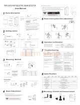
8.4 BEAM INTERRUPTION TIME
The beam interruption time defines the amount of time an intruder must be in the
beam path before an alarm is output. For instance, if the interruption time is set at
100msec, the detector output an alarm only if the beams are blocked for more
than 100msec.
8.5 BEAM POWER CONTROL
The beam strength is at optimal level if used at the maximum range.
If used for shorter distance, excess beam energy reaches the receiver, resulting in
reflection on the nearby walls and cross-talking with other detectors.
8.7 HIGH DENSITY (This is a special feature for stacking gates.)
- By connecting HIGH DENSITY CONNECTION (OUT) of the receiver [1] and HIGH DENSITY CONNECTION (IN) of the receiver [2], AND GATE can
be formed between the lower beam of the receiver [1] and the upper beam of the receiver [2].
Alarm is output to the receiver [2].
- By connecting HIGH DENSITY CONNECTION (OUT) of the receiver [2] and HIGH DENSITY CONNECTION (IN) of the receiver [3], AND GATE can
be formed between the lower beam of the receiver [2] and the upper beam of the receiver [3].
Alarm is output to the receiver [3].
- Up to 8 units can be connected.
- Only alarm operations are interlinked.
Other features including the EDC function independently in each of the receivers.
Caution : All of the receivers to be connected must have AND GATE setting and the same sensitivity.
- Connecting high density connection cables
Connect the high density connection cables that come with the product.
Caution : The length of these cables must be within 2m.
Caution : The connection of OUT and IN must be made 1 to 1, and do not connect them in parallel.
Beam energy decreases as it flies a
long distance.
For shorter range, more beam energy
reaches the receiver.
8.2 SELECTABLE AND/OR GATE
The unit has photoelectric intrusion detection system designed to provide an
alarm relay activation upon the detection of an intruder moving through four
pulsed infrared beams (AND GATE), and also moving through either of the
upper two beams or the lower two beams (OR GATE).This AND/OR GATE is
selectable with the dip switches for required protection.
8.3 EDC (Environmental Discrimination Circuit)
EDC sends EDC signal when it becomes difficult to maintain stable operation
due to environmental disturbance like fog or rain.
There are two selective features in utilizing the Bypass switch at the receiver.
Hereunder, the condition where it is difficult to maintain stable operation for
more than 3 seconds due to unfavorable environmental condition is defined as
"Poor Environmental Condition".
BYPASS switch =====> OFF
1) In Poor Environmental Condition
EDC LED will turn on and EDC signal will be provided through the normal
closed relay output at the receiver.
The alarm signal will then be generated by the further loss of the beam
energy.
2) When either optical module is blocked for 3 seconds
EDC LED will turn on and EDC signal will be provided. No alarm output
will be generated.
3) When both optical modules are blocked for 3 seconds
After the specified interruption time, alarm LED turns on and alarm signal
is generated. If beams are blocked for more than 3 seconds, EDC LED
will turn on and EDC signal will be provided.
BYPASS switch =====> ON
1) In Poor Environmental Condition
EDC LED will turn on and EDC signal will be provided through the normal
closed relay output at the receiver.
With the further loss of beam energy, the alarm LED turns on but alarm
signal is NOT generated (alarm relay is automatically shunted).
2) When either optical module is blocked for 3 seconds
EDC LED will turn on and EDC signal will be provided. If another optical
module is blocked, alarm LED turns on but no alarm signal is generated.
3) When both optical modules are blocked for 3 seconds
After the specified interruption time, alarm LED turns on and alarm signal
is generated. Even if the beams are blocked for more than 3 seconds,
EDC LED will not turn on and EDC signal is not provided.
Note : It is extremely important to have the EDC connected to a trouble circuit.
It is also important to check the system any time the EDC relay has been
activated.
Note : EDC feature has not been evaluated by UL.
Max Detection Range
Short Range
One LED displays the amount of beams received during optical module
adjustment.
As more beam energy is received, the illumination time shortens as follows:
ON OFF once OFF twice OFF three times Flashing ON three times
ON twice ON once OFF.
When the LED turns off, the alignment is complete.
8.6 LEVEL LED
ON
OFF once
OFF twice
OFF three times
Flashing
ON three times
ON twice
ON once
OFF
LEVEL LED
OUT
IN
OUT
IN
OUT
IN
Receiver [1]
Receiver [2]
Receiver [3]
Transmitter [2]
Alarm
Intruder
OUT
IN
OUT
IN
Transmitter [1] Receiver [1]
Transmitter [3]
Receiver [2]
Receiver [3]
ALARM
E+ E- COM NC NO COM NC COM NC
POWER ALARM EDC TAMPER
IN OUT
HIGH DENSITY
CONNECTION
EDC
1 2 3 4 5 6
ON
100
75
40
150
200
300
400
500
INTERRUPTION
ALIGNMENT
TESTER LEVEL
3.4V
~
: EXCELLENT
3.0V
~
: GOOD
0.0V
~
: POOR
CHRCK
TERMINALS
TIME(msec)
LEVEL
FUNCTIONNo. OFF ON
A BGROUP
AND ORAND/OR
1
2 3M 1
ON ON2 OFF OFF
OFF ON3
4
OFF ONBYPASS5
LOWER
BEAM
UPPER
BEAM
LEVEL
CHECK
6
OFF ON
Knockout

16 OPTIONAL PARTS
14 DIMENSIONS
- At least once a year, clean the optical module and covers with a soft cloth,
and perform walk testing to verify operation.
- The specifications are subject to change without prior notice.
- This unit designed to detect movement of an intruder and activates an alarm
control panel.
- Being only a part of a complete system, we can not accept responsibility for
any damages or other consequences resulting from an intrusion.
17 OTHER INFORMATION
12 OPERATION CHECK
11 ALIGNMENT
When installing only 1 set, beam group/channel setting and synchro wires are not required.
Use the unit at all original positions (OFF) on the switch No. 1 to 3 of the transmitter and the receiver.
[1] SYSTEM III must be set to group B to avoid crosstalking to SYSTEM I.
[2] SYSTEM IV must be set to group B to avoid crosstalking to SYSTEM II.
[3] Stay set to channel M on both groups and synchro wires are not required.
10 SELECTABLE BEAMS AND SYNCHRO WIRING
AND/OR GATE (on the receiver)
Set the dip switch No.4 on the receiver to:
ON : OR GATE
OFF : AND GATE (original Position)
BYPASS (on the receiver)
Set the dip switch No.5 on the receiver to:
ON : BYPASS activated
OFF : BYPASS not activated (original Position)
LEVEL CHECK (on the receiver)
Set the dip switch No.6 on the receiver to:
ON : Performs label display and tester output of the upper beam
OFF : Performs label display and tester output of the lower beam
(original Position)
BEAM INTERRUPTION TIME (on the receiver)
Adjust with the rotary volume switch on the receiver.
Slower setting reduce sensitivity.
(original Position : 40msec)
BEAM POWER CONTROL (on the transmitter)
Turn the volume on the transmitter clockwise to increase beam power and
counterclockwise to decrease beam power.
Refer to the following chart to set the volume based on the detection range
(initial setting at maximum length).
9 INITIAL SETTING
Note: For UL applications the interruption time shall not exceed 75 msec.
Slow movingRunning
40msec
Jogging
Normal walking
Slow walking
61 2 4
Fast walking
3 5
500msec100msec 300msec200msec 400msec
AND/OR Switch
(switch no.4)
Bypass Switch
(switch no.5)
Level Check Switch
(switch no.6)
BEAM INTERRUPTION TIME
Sensitivity Volume
ALARM
E+ E- COM NC NO COM NC COM NC
POWER
ALARM EDC
TAMPER
IN OUT
HIGH DENSITY
CONNECTION
EDC
100
75
40
150
200
300
400
500
INTERRUPTION
ALIGNMENT
TESTER LEVEL
3.4V
~
: EXCELLENT
3.0V
~
: GOOD
0.0V
~
: POOR
CHRCK
TERMINALS
TIME(msec)
LEVEL
FUNCTIONNo. OFF ON
A BGROUP
AND ORAND/OR
1
2 3M 1
ON ON2 OFF OFF
OFF ON3
4
OFF ONBYPASS
5
LOWER
BEAM
UPPER
BEAM
LEVEL
CHECK
6
OFF ON
1 2
ON
3 4 5 6
Receiver
Model
20
0-20m
0-60m
60
0-40m
40
NR60AQM
NR120AQM
NR200AQM
Volume
Range
Volume
Range
Volume
Range
20-30m
60-100m
100
40-60m
60
30
30-40m
100-130m
130
60-80m
80
40
40-50m
130-160m
160
80-100m
100
50
50-55m
160-180m
180
100-110m
110
55
55-60m
180-200m
200
110-120m
120
60
Volume Setting of Beam Power Control (OUT DOOR)
Model
40
0-40m
0-120m
120
0-80m
80
NR60AQM
NR120AQM
NR200AQM
Volume
Range
Volume
Range
Volume
Range
40-60m
120-200m
200
80-120m
120
60
60-80m
200-260m
260
120-160m
160
80
80-100m
260-320m
320
160-200m
200
100
100-110m
320-360m
360
200-220m
220
110
110-120m
360-400m
400
220-240m
240
120
Volume Setting of Beam Power Control (IN DOOR)
Beam Power Control
POWER
E+ E- COM NC
POWER
400
200
INDOOR 120
OUTDOOR 60
200
100
360
180
260
130
320
160
BEAM POWER
CONTROL(m)
TAMPER SYNCHRO
FUNCTIONNo. OFF ON
A BGROUP1
2 3M 1
ON ON2 OFF OFF
OFF ON3
4
OFF ON
1 2
ON
3 4
Transmitter
* The diagram is NR200AQM
10.3 EXAMPLES
The selectable beams up to 8 kinds can be used. The unit has Group A and B beam for
selection. Each group can be divided into 4 channels which are called Channel M (Master),
Channel 1, Channel 2, and Channel 3. Channel 1 to 3 can emit beams only when Channel M
on the same group provides each channel with synchro signal. When installing 2 or more sets
on the same group, set only 1 set to Channel M and set the other sets to Channel 1 to 3. And
synchro wires are required. (See SYNCHRO WIRING.)
Set the dip switch No.1 to 3 on each transmitter and receiver for group/channel selection. See
below chart.
10.1 BEAM GROUP/CHANNEL
BEAM GROUP A CHANNEL M
CHANNEL 1
CHANNEL 2
CHANNEL 3
GROUP B CHANNEL M
CHANNEL 1
CHANNEL 2
CHANNEL 3
* Each transmitter and receiver to be faced must be set to the
same group/channel.
* When installing 2 or more sets, do not set to the same
group/channel to avoid crosstalking.
GROUP
B
A
SWITCH NO.1
GROUP SELECTION
ON
OFF
SWITCH NO.3
OFF
ON
CHANNEL
M
1
SWITCH NO.2
CHANNEL SELECTION
OFF
OFF
OFF
ON
2
3
ON
ON
Receiver
SWITCH NO.1~3
ALARM
E+ E- COM NC NO COM NC COM NC
POWER ALARM EDC TAMPER
IN OUT
HIGH DENSITY
CONNECTION
EDC
100
75
40
150
200
300
400
500
INTERRUPTION
ALIGNMENT
TESTER LEVEL
3.4V
~
: EXCELLENT
3.0V
~
: GOOD
0.0V
~
: POOR
CHRCK
TERMINALS
TIME(msec)
LEVEL
FUNCTIONNo. OFF ON
A BGROUP
AND ORAND/OR
1
2 3M 1
ON ON2 OFF OFF
OFF ON3
4
OFF ONBYPASS5
LOWER
BEAM
UPPER
BEAM
LEVEL
CHECK
6
OFF ON
1 2
ON
3 4 5 6
POWER
E+ E- COM NC
POWER
400
200
INDOOR 120
OUTDOOR 60
200
100
360
180
260
130
320
160
BEAM POWER
CONTROL(m)
TAMPER SYNCHRO
FUNCTIONNo. OFF ON
A BGROUP1
2 3M 1
ON ON2 OFF OFF
OFF ON3
4
OFF ON
1 2
ON
3 4
Transmitter
SWITCH NO.1~3
SWITCH NO.4 is NULL
Synchro wires are required when installing 2 or more sets on the same group. Do
wire between terminal "SYNCHRO" of each transmitter on the same group.
This synchro wire should be more than 0.65mm Dia.(0.3mm
2
) and should be run
within 66ft.(20m) length.
Synchronized transmitters must use a common power supply. Synchro wires are
not required between the receivers. Do not wire between group A and B.
* The system will not be activated when synchro wires are not connected properly
or other unneeded wires are connected.
(When required wires are not connected, Power LED will be flickered.)
10.2 SYNCHRO WIRING
CAUTION
When Power LED is flickered, shut off the power and reconnect wires correctly.
• 1 STACKING IN LONG DISTANCE
[1] SYSTEM III must be set to group B to avoid crosstalking to SYSTEM I.
[2] SYSTEM IV must be set to group B to avoid crosstalking to SYSTEM II.
[3] Each top line set must be set to chennel M and the bottom line sets to channel
1 to avoid crosstalking between the top and bottom line sets.
[4] Do synchro wire on each group due to multiple channel use.
[1] SYSTEM III must be set to group B to avoid crosstalking to SYSTEM I.
[2] SYSTEM IV must be set to group B to avoid crosstalking to SYSTEM II.
[3] Each top line set must be set to chennel M and the other line sets to channel
1~2 to avoid crosstalking between the stacking sets.
[4] Do synchro wire on each group due to multiple channel use.
• 2 STACKING IN LONG DISTANCE
GROUP A
CHANNEL M
SYSTEM I
R T
GROUP A
CHANNEL M
SYSTEM II
T R
GROUP B
CHANNEL M
SYSTEM III
R T
GROUP B
CHANNEL M
SYSTEM IV
T R
• 3 STACKING IN LONG DISTANCE
GROUP A
CHANNEL M
R T
GROUP A
CHANNEL M
T R
GROUP B
CHANNEL M
R T
GROUP B
CHANNEL M
T R
GROUP A
CHANNEL 1
SYSTEM I
R T
GROUP A
CHANNEL 1
SYSTEM II
T R
GROUP B
CHANNEL 1
SYSTEM III
R T
GROUP B
CHANNEL 1
SYSTEM IV
T R
SYNCHRO WIRING TERMINAL "SYNCHRO"
SYSTEM I SYSTEM II SYSTEM III SYSTEM IV
GROUP A
CHANNEL M
R T
GROUP A
CHANNEL M
T R
GROUP B
CHANNEL M
R T
GROUP B
CHANNEL M
T R
GROUP A
CHANNEL 1
R T
GROUP A
CHANNEL 1
T R
GROUP B
CHANNEL 1
R T
GROUP B
CHANNEL 1
T R
GROUP A
CHANNEL 2
R T
GROUP A
CHANNEL 2
T R
GROUP B
CHANNEL 2
R T
GROUP B
CHANNEL 2
T R
SYNCHRO WIRING TERMINAL "SYNCHRO"
[1] SYSTEM III must be set to group B to avoid crosstalking to SYSTEM I.
[2] SYSTEM IV must be set to group B to avoid crosstalking to SYSTEM II.
[3] Each top line set must be set to chennel M and the other line sets to
channel 1~3 to avoid crosstalking between the stacking sets.
[4] Do synchro wire on each group due to multiple channel use.
• 4 STACKING IN LONG DISTANCE
GROUP A
CHANNEL M
R T
GROUP A
CHANNEL M
T R
GROUP B
CHANNEL M
R T
GROUP B
CHANNEL M
T R
GROUP A
CHANNEL 1
R T
GROUP A
CHANNEL 1
T R
GROUP B
CHANNEL 1
R T
GROUP B
CHANNEL 1
T R
GROUP A
CHANNEL 2
R T
GROUP A
CHANNEL 2
T R
GROUP B
CHANNEL 2
R T
GROUP B
CHANNEL 2
T R
GROUP A
CHANNEL 3
R T
GROUP A
CHANNEL 3
T R
GROUP B
CHANNEL 3
R T
GROUP B
CHANNEL 3
T R
SYNCHRO WIRING TERMINAL "SYNCHRO"
SYSTEM II SYSTEM III SYSTEM IVSYSTEM I
There are two ways of optical module alignment: using the level LED and a voltmeter.
11.1 Alignment Using the Level LED
Alignment of the Upper Beam
(1) Set the dip switch No.6 on the receiver to ON.
(2) While looking into the scope at the center of the lens
from a location 10 to 15 cm away, adjust the
horizontal direction by rotating the turntable and the
horizontal adjustment screw. Also, adjust the vertical
direction by rotating the vertical adjustment screw. As
shown in Scope View, adjust to locate the sensor of
the receiver in the center of the viewing circle.
(3) Check the level LED of the receiver.
When the level LED is off, the alignment is complete.
If the level LED is not off, perform fine alignment of
the transmitter and receiver using the horizontal and
vertical adjustment screws. Repeat it until the level
LED goes off.
Scope View
Turntable
Vertical
Adjustment
Screw
Horizontal
Adjustment
Screw
11.2 Alignment Using a Voltmeter
(1) Insert the voltmeter leads into the alignment check terminals of the receiver.
Set the voltmeter to the DC voltage mode.
(2) Adjust the upper and lower optical modules according to "11.1 Alignment
Using the Level LED" so that the output value of the voltmeter reads 3.0V or
higher.
12.1 ALARM OPERATION
- AND GATE : Check that the alarm LED on the receiver turns ON when all for beams are blocked simultaneously for the adjusted beam interruption time.
- OR GATE : Check that the alarm LED on the receiver turns ON when either of the upper/lower two beams are blocked for the adjusted beam interruption time.
12.3 PERIODEC CHECK
This system should be tested at least once a week per above checking to ensure proper function.
12.2 EDC OPERATION
(1) When OR GATE is set, set the dip switch No.4 on the receiver to OFF (AND GATE).
(2) Check that the EDC LED on the receiver turns ON in 3 seconds after only the upper beam is blocked.
(3) Check that the ALARM LED on the receiver turns ON in the adjusted beam interruption time after the lower beam is blocked while the EDC LED stays ON.
(4) Check that the EDC LED on the receiver turns ON in 3 seconds after only the lower beam is blocked.
(5) Check that the ALARM LED on the receiver turns ON in the adjusted beam interruption time after the upper beam is blocked while the EDC LED stays ON.
(6) Set the dip switch No.4 on the receiver to ON for OR GATE.
ALARM
E+ E- COM NC NO COM NC COM NC
POWER ALARM EDC TAMPER
IN OUT
HIGH DENSITY
CONNECTION
EDC
100
75
40
150
200
300
400
500
INTERRUPTION
ALIGNMENT
TESTER LEVEL
3.4V
~
: EXCELLENT
3.0V
~
: GOOD
0.0V
~
: POOR
CHRCK
TERMINALS
TIME(msec)
LEVEL
FUNCTIONNo. OFF
ON
A B
GROUP
AND ORAND/OR
1
2 3
M 1
ON
ON
2
OFF OFF
OFF
ON
3
4
OFF ONBYPASS
5
LOWER
BEAM
UPPER
BEAM
LEVEL
CHECK
6
OFF ON
1 2
ON
3 4
5 6
OFF
Receiver Console
ALARM
E+ E- COM NC NO COM NC COM NC
POWER ALARM EDC TAMPER
IN OUT
HIGH DENSITY
CONNECTION
EDC
100
75
40
150
200
300
400
500
INTERRUPTION
ALIGNMENT
TESTER LEVEL
3.4V
~
: EXCELLENT
3.0V
~
: GOOD
0.0V
~
: POOR
CHRCK
TERMINALS
TIME(msec)
LEVEL
FUNCTIONNo. OFF
ON
A B
GROUP
AND
OR
AND/OR
1
2 3
M 1
ON
ON
2
OFF OFF
OFF
ON
3
4
OFF
ON
BYPASS
5
LOWER
BEAM
UPPER
BEAM
LEVEL
CHECK
6
OFF ON
1 2
ON
3 4 5 6
Receiver Console
Switch No.6
ALARM
E+ E- COM NC NO COM NC COM NC
POWER ALARM EDC TAMPER
IN OUT
HIGH DENSITY
CONNECTION
EDC
100
75
40
150
200
300
400
500
INTERRUPTION
ALIGNMENT
TESTER LEVEL
3.4V
~
: EXCELLENT
3.0V
~
: GOOD
0.0V
~
: POOR
CHRCK
TERMINALS
TIME(msec)
LEVEL
FUNCTIONNo. OFF ON
A BGROUP
AND ORAND/OR
1
2 3
M 1
ON ON
2
OFF OFF
OFF ON3
4
OFF ONBYPASS
5
LOWER
BEAM
UPPER
BEAM
LEVEL
CHECK
6
OFF ON
1 2
ON
3 4 5 6
Receiver Console
ALIGNMENT
CHECK
TERMINALS
Alignment of the Lower Beam
(4) Set the dip switch No.6 on the receiver to OFF.
(5) Perform lower beam alignment according to steps (2)
and (3) above.
When the level LED goes off, the alignment is
complete.
Check the following items if the system does not work normally.
(1) Check that the input voltage is 10.5~28VDC at the terminal on both of the transmitter and the receiver.
(2) Check that the loop resistance of the alarm output is under 100 Ω.
(3) Check that the monitor LED on the transmitter turns ON.
(4) Check that the alarm LED on the receiver turns ON when both of the upper/lower beams are blocked simultaneously for the adjusted beam interruption time.
(5) Check that the output of the beam alignment check terminal on the receiver is over 3V.
(6) Check that the level LED on the receiver turns OFF.
13 TROUBLESHOOTING
15 SPECIFICATIONS
4-2
-2 SHIN-MIYAKODA, KITAKU, HAMAMATSU, SHIZUOKA 431-2103 JAPAN PHONE: +81-53-428-4116 FAX: +81-53-428-4119
Copyright © 2013 Atsumi Electric Co., Ltd. NR60AQM/120AQM/200AQM Installation Manual
AEX
000150
CAUSE
Something is blocking the beams.
Optical modules or covers need cleaning.
Improper channel selection.
Syncro wires are not connected.
Something move is blocking the beams.
Beam interruption time is set too quick.
Near by source of electrical noise or RFI.
Wiring too close to power sources or power line.
Unstable installation site.
Over the maximum protection range of the model.
Inappropriate Beam Power Control level.
Frost or dew.
Beams are reflected into the receiver.
Beam interruption time is set too slow.
Other beams are received by the receiver.
Something is blocking the beams.
Installed on unstable ground.
Over the maximum protection range of the model.
Inappropriate Beam Power Control level.
Frost or dew.
Required synchro wires are not connected.
PROBLEM SOLUTION
Remove the object(s).
Clean the optical modules and the covers.
Select the proper channels.
Connect the proper synchro wiring.
Remove the object(s).
Decrease the sensitivity.
Change the installation site.
Change the wiring route.
Fix the installation site.
Reinstall within the maximum range.
Readjust the control level.
Attach the optical heater.
Remove the reflective object or change the installation site.
Increase the sensitivity.
Adjust beams power of the transmitter.
Change the installation site.
Remove the object(s).
Fix the installation site.
Reinstall within the maximum range.
Readjust the control level.
Attach the optical heater.
Connect the proper synchro wiring.
Constant alarm output
False alarms often caused.
No alarm when beams brocked.
EDC LED often turns ON.
Power LED on the transmitter flicker.
Center of the Lower Beam
398
337.7
220
39 39.7
244 77.1
Wire Entrance (25×50)
19.3
103
Knockout
Center of the Upper Beam
96
56
Part No.
BP-1
BP-2
BP-3
PC1A
PC3A
BH12T
Description
Pole (ø42.7mm x 950mm 2-pcs)
Pole (ø42.7mm x 1200mm 2-pcs)
Wall-mount Pole (ø42.7mm 2-pcs)
Water Pesistant Enclosure (2-pcs)
Back-to-back Enclosure (1-pcs)
Heater
* Specifications are subject to change without prior notice.
PRODUCT NAME
Model
Input Voltage
Operating Temp./Humid.
Preservable Temp./Humid.
Alarm Output
Selectable Beams
Max Coverage
Beam Interruption Time
Optical Module
Installation Site
IP Rate
Net Weight
Color
PHOTOELECTRIC BEAM DETECTOR
10.5~28VDC (Non-Polarity)
-13°F~+140°F (-25°C ~ +60°C) under 95%RH
-22°F~+158°F (-30°C ~ +70°C) under 95%RH
From C 0.2A@30VDC Output Period: 3sec
NC 0.2A@30VDC Output Period: 3sec
NC 0.1A@30VDC Output Period: While the cover is removed.
2Groups x 4Channels
40msec ~ 500msec (variable)
±90° Horizontal ±10° Vertical Adjustable
Outdoor / Indoor (Pole / Wall Mount)
IP 66
Transmitter: 2.86lb (1.3kg) / Receiver: 2.86lb (1.3kg)
Black Mansel - 1.0
Alam
EDC
Tamper
Transmitter: under 28mA
Receiver: under 100mA
NR120AQM NR200AQM
Transmitter: under 24mA
Receiver: under 100mA
Outdoor 400ft.(120m)
NR60AQM
Transmitter: under 20mA
Receiver: under 100mA
Current Draw
Outdoor 200ft.(60m) Outdoor 660ft.(200m)
* Specifications are subject to change without prior notice.
/