Page is loading ...

MegaPower 168
Matrix Switcher/Controller System
Installation & Service Manual


MegaPower 168
Matrix Switcher/Controller System
Installation & Service Manual
Copyright 2002
All rights reserved.
No part of this manual may be reproduced in any form
without written permission from Sensormatic
®
Electronics Corporation.
8000-0934-01, Revision C
06/02

WARNING
Do not install this product in hazardous areas where highly combustible or explosive
products are stored or used.
FCC COMPLIANCE
This equipment has been tested and found to comply with the limits for a Class A digital device, pursuant to Part 15 of the FCC
Rules. These limits are designed to provide reasonable protection against interference when the equipment is operated in a
commercial environment. The equipment generates, uses, and can radiate radio frequency energy and, if not installed and used in
accordance with the instruction manual, may cause interference to radio communications.
Operation of this equipment in a residential area may cause interference in which case the user will be required to correct the
interference at his own expense.
EQUIPMENT MODIFICATION CAUTION
Equipment changes or modifications not expressly approved by Sensormatic Electronics Corporation, the party responsible for FCC
compliance, could void the user's authority to operate the equipment, and could create a hazardous condition.
WARRANTY DISCLAIMER
Sensormatic Electronics Corporation makes no representation or warranty with respect to the contents hereof and specifically
disclaims any implied warranties of merchantability or fitness for any particular purpose. Further, Sensormatic Electronics
Corporation reserves the right to revise this publication and make changes from time to time in the content hereof without obligation
of Sensormatic Electronics Corporation to notify any person of such revision or changes.
American Dynamics, the AD logo, Sensormatic, the Sensormatic hand logo, and TouchTracker are all registered trademarks of
Sensormatic Electronics Corporation

Table of Contents
PREFACE .................................................................................................................... I
Who Should Use This Manual ............................................................................................................... i
How To Use This Manual ....................................................................................................................... i
Related Documents ................................................................................................................................ ii
Ordering Documents.............................................................................................................................. ii
Questions? .............................................................................................................................................. ii
CHAPTER 1 DESCRIPTION........................................................................................ 1-1
GENERAL DESCRIPTION ...................................................................................................................... 1-1
MP168 Bay Construction.................................................................................................................... 1-2
Bay Housing - Front ........................................................................................................................ 1-2
Front Panel....................................................................................................................................... 1-2
MP168 Bay Modules........................................................................................................................ 1-2
Circuit Cards .................................................................................................................................... 1-2
Bay Housing - Rear ......................................................................................................................... 1-3
Rear Panel Assembly...................................................................................................................... 1-3
POWER SUPPLY MODULE .................................................................................................................... 1-4
Power Supply Module Features......................................................................................................... 1-4
A. Printer Port ................................................................................................................................. 1-4
B. Data Line BNC Connectors....................................................................................................... 1-4
C. ARCNET Connector................................................................................................................... 1-5
D. Primary Power Connector ........................................................................................................ 1-5
E. Redundant Power Connector................................................................................................... 1-5
F. External Sync I/O Connectors .................................................................................................. 1-5
Color Code ....................................................................................................................................... 1-5
CENTRAL PROCESSING UNIT MODULE ............................................................................................. 1-6
Connections..................................................................................................................................... 1-7
Program Monitor.............................................................................................................................. 1-7
Color Code ....................................................................................................................................... 1-7
VIDEO INPUT MODULES........................................................................................................................ 1-8
Video Input Module 1 .......................................................................................................................... 1-9
Video Input Modules 2 and 3 ............................................................................................................. 1-10
Video Input Module 4 .......................................................................................................................... 1-11
VIDEO OUTPUT MODULE ...................................................................................................................... 1-12
Color Code ....................................................................................................................................... 1-13
CONTROL CODE MODULE.................................................................................................................... 1-14
Control Code Module (CCM) Bay Slot............................................................................................... 1-14
AD Manchester Code Terminal.......................................................................................................... 1-14
SEC RS-422 Code Terminal ............................................................................................................... 1-14
Color Code ....................................................................................................................................... 1-15
SPECIFICATIONS.................................................................................................................................... 1-16
Electrical Specifications..................................................................................................................... 1-16
Mechanical Specifications ................................................................................................................. 1-16
Environmental Specifications............................................................................................................ 1-16
Computer Interface Requirements (Minimum)................................................................................. 1-17
Video Input Specifications ................................................................................................................. 1-17
Video Output Specifications .............................................................................................................. 1-17
Regulatory ........................................................................................................................................... 1-17
Product Codes..................................................................................................................................... 1-18

CHAPTER 2 INSTALLATION ...................................................................................... 2-1
Before You Begin.................................................................................................................................... 2-1
Verification of Equipment and Unpacking ....................................................................................... 2-1
Remove Module Retainer ................................................................................................................... 2-1
About Connection Diagrams ............................................................................................................. 2-1
Single MP168 Bay Components ........................................................................................................ 2-2
Dual MP168 Bay Components ........................................................................................................... 2-2
Installation............................................................................................................................................... 2-3
Required Tools and Equipment......................................................................................................... 2-3
Recommended Video Cable............................................................................................................... 2-3
Recommended Data Cable................................................................................................................. 2-3
MOUNTING .............................................................................................................................................. 2-4
POWER & DATA CONNECTION ............................................................................................................ 2-5
Primary Power Line Cord ................................................................................................................... 2-5
Primary Power Connections .............................................................................................................. 2-5
Redundant Power Supply .................................................................................................................. 2-5
Redundant Power Supply Connections ........................................................................................... 2-6
CENTRAL PROCESSING UNIT MODULE CONNECTIONS ................................................................. 2-7
RS-232 Connections ........................................................................................................................... 2-7
CONTROL CODE MODULE CONNECTIONS ........................................................................................ 2-8
SensorNet Connections ..................................................................................................................... 2-8
AD Manchester Control Code Configurations ................................................................................. 2-8
Daisy Chain Configuration................................................................................................................. 2-8
Star Configuration ........................................................................................................................... 2-9
RS-422 Connections ........................................................................................................................... 2-10
VIDEO INPUT MODULE CONNECTIONS .............................................................................................. 2-12
VIM-1 Connections.............................................................................................................................. 2-12
VIM-2 to VIM-3 Connections............................................................................................................... 2-13
Dual Bay Video Input Connections................................................................................................2-13
Ribbon Cable Connections ............................................................................................................ 2-13
VIM-4 Modules and Loop Panels (Single Bay) ................................................................................. 2-14
Ribbon Cable Connections ............................................................................................................ 2-14
VIM-4 Modules and Loop Panels (Dual Bay) .................................................................................... 2-15
VIDEO OUTPUT MODULE CONNECTIONS .......................................................................................... 2-16
Video Output Connections ............................................................................................................. 2-16
VIDEO OUTPUT MODULE JUMPER SETTINGS................................................................................... 2-17
Single Bay Configuration ................................................................................................................... 2-17
Dual Bay Configuration ...................................................................................................................... 2-17
DUAL BAY CONNECTIONS ................................................................................................................... 2-18
EXTERNAL SYNCHRONIZER CONNECTION ....................................................................................... 2-19
Setting Vertical Phase ........................................................................................................................ 2-19
CONNECTING PERIPHERALS AND ACCESSORIES .......................................................................... 2-20
Parallel.................................................................................................................................................. 2-20
Printer Connection.............................................................................................................................. 2-20
PC Connection .................................................................................................................................... 2-21
External System Controller Connection...........................................................................................2-23

APPENDIX A ...............................................................................................................A-1
DIMENSIONS FOR MP168 BAY ............................................................................................................. A-1
System Control Devices (less than 2.1m-7 feet from MP168)................................................................ A-2
AD2079/AD2088 Operator Keyboards ........................................................................................... A-2
System Control Devices (greater than 2.1m - 7 feet)............................................................................. A-3
AD2079/AD2088 Operator Keyboards ........................................................................................... A-3
System Control Devices (less than 2.1m - 7 feet) ................................................................................. A-4
ADTT Touch Tracker Operator Keyboard ..................................................................................... A-4
System Control Devices (greater than 2.1m - 7 feet)............................................................................. A-5
ADTT Touch Tracker Operator Keyboard ..................................................................................... A-5
System Expansion Devices ................................................................................................................... A-6
AD1691 Manchester Code Distributor to Receiver/Driver and Pan/Tilt/Zoom Unit...................... A-6
AD1981 RS-232 Port Expander .......................................................................................................... A-7
AD2091 Control Code Converter....................................................................................................... A-8
AD2096A Alarm Interface Unit ........................................................................................................... A-9
AD1641M Manchester Control Code Receiver/Driver ..................................................................... A-10
APPENDIX B ...............................................................................................................B-1
TROUBLESHOOTING ............................................................................................................................. B-1
Section 1- Video Troubleshooting..................................................................................................... B-2
Section 2- Switcher System Troubleshooting ................................................................................. B-3
APPENDIX C ...............................................................................................................C-1
SensorNet Communications ................................................................................................................. C-1
SensorNet Connection on the MP168 CCM...................................................................................... C-1
Attaching to SensorNet ...................................................................................................................... C-1
Network Design Considerations ....................................................................................................... C-2
Network Topologies ............................................................................................................................... C-3
Daisy Chain Link Guidelines.............................................................................................................. C-3
Backbone Link Guidelines ................................................................................................................. C-4
Star Link Guidelines ........................................................................................................................... C-5
Network Checkout .................................................................................................................................. C-5
APPENDIX D ...............................................................................................................D-1
INDEX ....................................................................................................................................................... D-1


PREFACE
Who Should Use This Manual
•
•
•
•
•
Engineers, customer engineers, and installers who want to learn how the American Dynamics MegaPower 168
(MP168) Matrix Switcher/Controller System operates.
Customer engineers and installers who want to learn how the system is installed and serviced.
How To Use This Manual
This manual is divided into the following sections:
The DESCRIPTION section provides an introduction to the MP168 Matrix Switcher/Controller System as well as
general information about the individual components that comprise the system. This section also includes the MP168
Matrix Switcher/Controller System specifications.
The INSTALLATION section provides basic information about preparing for the installation of the MP168 Matrix
Switcher/Controller System with topics such as what is needed to install the system, what considerations must be
examined when planning the installation, and general information that will aid the installers. This section also provides
the necessary procedures required to install the system and adapt it to the operational environment.
The APPENDIX section is divided into three sub-sections:
The TYPICAL CONNECTIONS sub-section provides detailed diagrams for connecting external devices to the
MP168 Matrix Switcher/Controller System.
The SERVICE AND TROUBLESHOOTING sub-section contains specific information regarding procedures
when attempting to diagnose a particular problem with the installation.
An INDEX is provided in this manual to aid in finding particular topics in a more timely fashion.
i

ii
Related Documents
Additional information relating to the MP168 Matrix Switcher/Controller System can be found within the following
documents:
MegaPower 168 System Administrator’s Manual Part Number 8000-0935-*
ADTT TouchTracker
™ Operator Keyboard Installation and Operation Manual
Part Number 8000-1657-*
AD2088 Operator Keyboard Installation and Operation Manual
Part Number 8000-1811-*
AD2079 Operator Keyboard Installation and Operation Manual
Part Number 8000-1810-*
* Suffix 01 - English
02 - French
03 - German
04 - Spanish
05 - Portuguese
Ordering Documents
Additional copies of this Installation and Service manual may be obtained from your Sensormatic sales representative.
The document number for this manual (English language) is 8000-0934-01.
Questions?
For questions that this manual does not address, call Technical Support at
1-800-507-6268
or
FAX: (845) 624-7685

DESCRIPTION
MP168 Matrix Switcher/Controller System
MegaPower 168 Matrix Switcher/
Controller System
CHAPTER 1
DESCRIPTION
In this chapter:
General Description .................................................................................... 1-1
Provides information regarding the design of the MegaPower168 Switcher/Controller
System as well as a description of the individual components that comprise a system.
Specifications ............................................................................................... 1-16
Provides detailed information about the MegaPower168 Switcher/Controller System and
components.

DESCRIPTION
MP168 Matrix Switcher/Controller System

MP168 Matrix Switcher/Controller System
DESCRIPTION
GENERAL DESCRIPTION
The MP168 Matrix Switcher/Controller System is
designed to support plug-in modules having a broad
range of functionality. Plug-in modules include a
Power Supply module, a Central Processing Unit
module, an optional Control Code module, Video Input
modules, and Video Output modules. Built-in
expansion capabilities permit the addition of a second
MP168 Bay to increase the number of video output
devices supported.
The MegaPower 168 Matrix Switcher/Controller
System (hereafter referred to as the MP168) is an
integrated CCTV matrix switching and control system
for CCTV surveillance systems with multiple video
inputs, outputs, and control stations. Video inputs are
typically provided by local or remote cameras and other
video sources. Video output is viewed on monitors, or
recorded on VCRs located at system control points.
In addition to providing video input and output
switching, the MP168 system can respond to alarms
and perform auxiliary switching for the control of
gates, doors, lights, etc. Depending on the control
requirements of a given application, various AD
keyboards and accessory devices can be used in concert
with the system bays, cameras, and monitors.
External communications to system devices can be
achieved through a variety of protocols, including
Manchester Control Code, RS-232, RS-422, and
External ARCNET. A parallel printer port is standard
with each MP168 system to provide hard copy of
operating parameters and alarm events.
As delivered, the MP168 Matrix Switcher/Controller
System is completely configured and ready for
mounting in standard EIA rack units, with video inputs
terminated in 75 ohms, requiring only system
interconnections, video input and output connections,
and any optional accessory connections prior to
operation.
I
N
O
U
T
O
U
T
O
U
T
O
U
T
I
N
I
N
I
N
I
N
I
N
O
U
T
O
U
T
LOOP
THROUGH
I
N
O
U
T
O
U
T
O
U
T
O
U
T
I
N
I
N
I
N
I
N
I
N
O
U
T
O
U
T
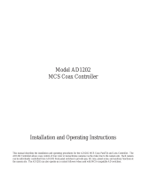
Figure 1-1 Standard Configuration of MP168 Video Matrix Switching System
Administrator
Computer
Video Inputs 1 - 168
Video Outputs 7 - 12
Video Outputs 1-6
1-1

DESCRIPTION
MP168 Matrix Switcher/Control System
MP168 Bay Construction
MP168 Bay Modules
Each Module in the Bay is comprised of two
components:
Bay Housing - Front
The MP168 Bay is a custom made enclosure that
houses all of the components of the MP168 Matrix
Switcher/Controller. The front section of the Bay
houses the Printed Circuit Cards and the Front Panel.
One rack mount ear is affixed to each side of front
section (see Figure 1-2).
•
•
A Circuit Card (see below), and
A Rear Panel Assembly, consisting of:
Rear Panel and Rear Panel Circuit Card
(see page 1-3)
Front Panel
Circuit Cards
The Front Panel of the MP168 Bay features a view
window that permits visual monitoring of the UOP
(Unit Operating Properly) LEDs.
The Circuit Card for each module resides in the front
section of the MP168 Bay (see Figure 1-2). The Circuit
Card communicates to its corresponding Rear Panel
Assembly through a Mid-Plane. The Mid-Plane has
integral mating connectors in the front and in the rear
for each circuit card to plug into.
The Front Panel is held on by two captive screws for
quick removal during service operations.
Figure 1-2 - MP168 Switcher/Controller Front Panel and Bay
Circuit
Card
UOP LED
Captive
Screw
View
Window
Rack Mount Ears
Rack Mount Ears
Front Panel
MP168 Bay
1-2

MP168 Matrix Switcher/Controller System
DESCRIPTION
Bay Housing - Rear
The rear of the MP168 Bay houses the various Rear
Panel Assemblies that provide the versatility of the
MP168 Switcher/Controller (see Figure 1-3).
Rear Panel Assembly
Each MP168 module includes a Rear Panel Assembly
consisting of a Rear Panel and a Rear Panel Circuit
Card.
Rear Panel
The Rear Panel provides the entry/exit point for signals
from and to external peripheral devices as well as for
inter-bay communications.
Figure 1-3 - MP168 Bay and Rear Panels
MP168 Bay
Rear Panel
Rear Panel Assembl
y
1-3

DESCRIPTION
MP168 Matrix Switcher/Control System
POWER SUPPLY MODULE
The Power Supply Module (PSM) features an on-
board switching power supply that converts 90-240 volt
(47-63Hz) AC input power to ±8 volt DC power for
internal use by all system modules.
In the event of a loss of AC power, the Power Supply
Module has provisions to accept an ±8 Volt DC
redundant power source (not provided). An internal
monitoring circuit senses the loss of primary voltage
and automatically switches to the redundant power
supply, effectively eliminating any disturbance to
system functions.
The Power Supply module also provides a 0-5VDC
square wave “Line-Sync” signal that is in-phase and
synchronized to the primary power source to
automatically synchronize internal switching functions.
•
•
•
•
The Power Supply Module always resides in
slot R (determined by the lettered slot
designation screening on the front and rear bay
surface). See Figure 1-4A.
The front and rear sections of the Power
Supply Module are identified with a RED
color code dot affixed to the respective
section.
The Power Supply Module includes the following
components:
PSM Circuit Card
PSM Rear Panel Assembly consisting of:
Rear Panel and Rear Panel Circuit Card
Power Supply Module Features
A. Printer Port
The Rear Panel of the PSM provides a parallel port
(labeled A in Figure 1-4D) to connect to a system
printer for outputting operating events and setups.
B. Data Line BNC Connectors
The PSM provides high-speed data line BNC
terminals (labeled B in Figure 1-4D). The IN/OUT
terminals are for looping to external system bays.
The second data line OUT terminal provides
MP168 data line outputs to external devices such
as Control Code distributors and receivers.
Front View
A
B
C
D
E
F
G
H
I
J
K
L
M
N
O
P
Q
R
Rear View
A
B
C
D
E
F
G
H
I
J
K
L
M
N
O
P
Q
R
Figure 1-4A - MP168 PSM Slot Designations (Front & Rear)
PSM Installation Slot (R)
Figure 1-4B - PSM Circuit Card In Bay
PSM Circuit
Card
1-4

MP168 Matrix Switcher/Controller System
DESCRIPTION
Color Code
C. ARCNET Connector
The Power Supply Module features a red code marker
on the upper portion of the panel for easy identification
when performing system modifications or service.
An RJ-45 jack (labeled C in Figure 1-4D) is
provided to enable bay-to-bay communications via
the ARCNET protocol.
Color Code - RED
EXT
SYNC
OUT
DATALI NE
IN
IN
REDUNDANT
SUPPLY
PRI NTER
PORT
ARCNET
LOOP
THROUGH
OUT
OUT
CLASS 2 WIRI NG ONLY
Figure 1-4D - Power Supply Module Rear Panel
B
B
E
F
D
C
B
A
D. Primary Power Connector
The primary source of power for the MP168
Switcher enters the bay through the Primary Power
Connector (labeled D in Figure 1-4D). A mating
line cord that is tailored specifically to the national
or regional electrical requirements of the intended
installation site is provided with the module.
E. Redundant Power Connector
The Power Supply Module is capable of supporting
a redundant power supply to prevent a total loss of
power to the MP168 Switcher in instances where
problems occur with the primary power source.
The Power Supply Module provides a 10-pin port
(labeled E in Figure 1-4D) for the connection of a
redundant power supply.
F. External Sync I/O Connectors
An external AC Line synchronizer may be used
with the MP168 Switcher in cases where
synchronous line phasing is desired for the entire
system and all related components. An external
sync signal enters the MP168 Bay through the EXT
SYNC terminal (labeled F in Figure 1-4D) on the
Power Supply Module.
Note: The External Sync OUT connector is not a sync
signal generated by the MP168 Switcher; it
merely provides a looping path for an external
synchronizer routed through the Switcher.
Figure -1 4C - PSM Rear Panel Assembly In Bay
1-5

DESCRIPTION
MP168 Matrix Switcher/Control System
CENTRAL PROCESSING
UNIT MODULE
The Central Processing Module includes the following
components:
The Central Processing Unit Module (CPM) performs
all switching control functions for single and dual bay
configurations, provides on-screen setup programming
menus (refer to the System Administrator Manual), and
dictates the functions of other modules in the MP168
system.
The Central Processing Unit module supports standard
switching system input devices including keyboards,
printers, external computers, alarms, and auxiliaries.
The CPM module is always installed next to the Power
Supply Module (see Figure 1-5A).
NOTE: Only one Central Processing Unit Module
is required for dual bay configurations.
An ARCNET repeater resident in the
Power Supply Module provides direct
control functions to the second bay.
•
•
•
•
CPM Circuit Card
CPM Rear Panel Assembly consisting of:
Rear Panel and Rear Panel Circuit Card
Figure 1-5B CPM Circuit Card In Bay
CPM Circuit
Card
The Central Processing Module always resides
in slot Q, determined by the lettered slot
designation screening on the front and rear bay
surface (see Figure 1-5A).
The front and rear sections of the Central
Processing Module are identified with a
PURPLE color code dot affixed to the
respective section.
Front View
A
B
C
D
E
F
G
H
I
J
K
L
M
N
O
P
Q
R
Rear View
A
B
C
D
E
F
G
H
I
J
K
L
M
N
O
P
Q
R
Figure 1-5A - MP168 CPM Slot Designations (Front & Rear)
CPM Installation Slot (Q)
1-6

MP168 Matrix Switcher/Controller System
DESCRIPTION
Connections
Color Code
The CPM module is provided with ten RJ-45 modular
jacks for connecting compatible devices to the MP168
system.
The Central Processing Unit Module features a purple
code marker on the upper portion of the panel for easy
identification when performing system modifications or
service.
The first two RJ-45 modular jacks are dedicated for use
with ETHERNET (jack 1) and ARCNET (jack 2)
communications (see Figure 1-5D).
Figure 1-5D - Central Processing Module Rear
Panel Port Designations
Color Code - PURPLE
RJ-45 Jack 1 = ETHERNET Port
RJ-45 Jack 2 = ARCNET
RJ-45 Jack 3 = RS-232 Port #1
RJ-45 Jack 4 = RS-232 Port #2
RJ-45 Jack 5 = RS-232 Port #3
RJ-45 Jack 6 = RS-232 Port #4
RJ-45 Jack 7 = RS-232 Port #5
RJ-45 Jack 8 = RS-232 Port #6
RJ-45 Jack 9 = RS-232 Port #7
RJ-45 Jack 10 = RS-232 Port #8
Default PC connection port
Jacks 3 through 10 are dedicated for use with RS-232
compatible devices such as AD1981 Port Expanders,
modems, control keyboards, Personal Computers, etc.
Jack 10 (RS-232 Port 8) is the default port for
connecting a Personal Computer to the MP168. Two
RS-232 cables with RJ45 connectors and terminal
blocks are provided with each MP168 System.
Program Monitor
A Program Monitor BNC connector provides video
output to a dedicated monitor for basic system setup
and control functions or can be connected directly to a
VIM video input and switched to any system monitor.
Figure 1-5C CPM Rear Panel Assembly In Bay
CPM Rea
r
Panel
1-7

DESCRIPTION
MP168 Matrix Switcher/Control System
VIDEO INPUT MODULES
• The MP168 VIM-4 module is used in single
and dual bay applications. VIM-4 modules are
used in conjunction with external Looping
Panels to route video signals into, through, and
out of the MP168 Bay. VIM-4 modules may
reside in slots A through O.
The MP168 Video Input Modules (VIMs) function by
recognizing the presence of a video signal and then
switching the signal to the Central Processing Unit.
Then, the video is switched to the appropriate Video
Output Module.
All video inputs to the MP168 system are connected to
the application specific VIM Rear Panels (see Figure 1-
6B). The VIM card receives switching instructions
from user keyboards, GUIs, and external systems with
the appropriate protocol.
In the MP168 Switching System, there are four types of
Video Input Modules (VIM-1, VIM-2, VIM-3, and
VIM-4). The Circuit Cards in all four VIM modules
are identical, only the Rear Panel Assemblies differ,
according to their intended function.
•
•
•
•
The front and rear sections of all MP168 VIM
modules are identified with a BLUE color
code dot affixed to the respective section.
Each MP168 Video Input Module includes the
following components:
VIM Circuit Card
VIM Rear Panel Assembly consisting of:
Application Specific Rear Panel and Rear
Panel Circuit Card
An MP168 VIM-1 module provides 12 direct
input channels for video sources. The MP168
Bay supports a maximum of 15 VIM-1
modules. VIM-1 modules can reside in slots A
through O determined by the letter slot
screening on the front and rear bay surface
(see Figure 1-6A).
• MP168 VIM-2 and VIM-3 modules are used
in dual bay applications. Installed in pairs and
joined by ribbon cables, VIM-2/VIM-3
module pairs provide 12 direct input channels
(6 per module) for video sources. VIM-
2/VIM-3 pairs can reside in slots A through O.
Figure 1-6B - MP168 VIM Rear
Panels
VIM-1 Rea
r
VIM-3 Rea
r
VIM-4 Rea
r
VIM-2 Rea
r
Front View
A
B
C
D
E
F
G
H
I
J
K
L
M
N
O
P
Q
R
Rear View
A
B
C
D
E
F
G
H
I
J
K
L
M
N
O
P
Q
R
Figure 1-6A - MP168 VIM Slot Designations (Front & Rear)
Video Input Module Installation Slots
(A through O)
1-8
/