Page is loading ...

THINLINE
TM
AND AQUALITE
TM
LCD KEYPAD
Installation Guide
FRI 2: 52 PM
1 2 3 4
5 6 7 8
9 0 CMD
A
C
B
D
F
E
G
I
H
J
L
K
V
X
W
S
U
T
P
R
Q
M
O
N
Y
Z
E
N
T
E
R
B
A
C
K

© 2017 Digital Monitoring Products, Inc.
Information furnished is believed to be accurate and reliable.
This information is subject to change without notice.

1
DESCRIPTION
Thinline Series (7060, 7063, 7070, 7073, 7160, 7163, 7170, and 7173) and Aqualite Series
(7060A, 7063A, 7070A, and 7073A) LCD keypads oer flexible features and functionality.
Each keypad provides:
• Custom 16-character home or business name in the display
• Four 2-button panic keys
• AC Power/Armed LED
• 32-character display
• Backlit keyboard and DMP logo
• Internal speaker
• Red keyboard lighting in alarm conditions
• Simple harness connection to 4-wire keypad bus
• Optional back-boxes for conduit or wall mount applications
Models 7070/A, 7073/A, 7170, and 7173
Provide four fully-programmable, Class B, Style A, supervised, power limited protection
zones that can be programmed for a variety of burglary and access control applications.
Models 7063/A, 7073/A, 7163, and 7173
Provide a built-in proximity card reader designed to read DMP/HID proximity credentials.
Models 7073/A and 7173
Provide a door strike relay and allow Wiegand input from external card readers.

2
INSTALL THE KEYPAD
All DMP keypad housings are designed to install on any 4” square box, 3-gang switch box,
DMP 695 and 696 back-box, or flat surface.
Wiring Specifications for Keypad Bus
When planning a keypad bus installation, keep in mind the following specifications:
• DMP recommends using 18 or 22–gauge unshielded wire for all keypad circuits.
Do not use twisted pair or shielded wire for keypad bus data circuits. To maintain
auxiliary power integrity when using 22–gauge wire, do not exceed 500 feet. When
using 18–gauge wire, do not exceed 1,000 feet. Install an additional power supply
to increase the wire length or add devices.
• Maximum distance for any one circuit (length of wire) is 2,500 feet regardless of
the wire gauge. This distance can be in the form of one long wire run or multiple
branches with all wiring totaling no more than 2,500 feet. As wire distance from
the panel increases, DC voltage on the wire decreases.
• Maximum number of devices per 2,500 feet circuit is 40.
Each panel allows a specific number of supervised keypads. Add additional
keypads in the unsupervised mode. Refer to the panel installation guide for the
specific number of supervised keypads allowed.

3
• Maximum voltage drop between the panel (or auxiliary power supply) and any
device is 2.0VDC. If the voltage at any device is less than the required level, add an
auxiliary power supply at the end of the circuit. When the voltage is too low, the
devices cannot operate properly. Refer to the Keypad Bus Wiring Application Note
(LT-2031) and the 710 Module Installation Sheet (LT-0310) for more information.
Keypad Specifications
MODEL
NORMAL/
STANDBY
CURRENT
ALARM
CURRENT
FOUR
ZONES
INTERNAL
PROX
READER
WIEGAND
INPUT
INTERNAL
DOOR
STRIKE
RELAY
7060/A, 7160 72mA 87mA
7063/A, 7163 85mA 100mA X
7070/A, 7170
72mA+1.6mA
per active zone
87mA+2mA
per active zone
X
7073/A, 7173
85mA+1.6mA
per active zone
100mA+2mA
per active zone
X X X X
Table 1: Keypad Specifications
Install the Keypad

4
Remove the Cover
The keypad housing is made up of two parts: the cover, which
contains the circuit board and components, and the base. Use the
following steps and Figure 1 to separate the keypad cover and
base:
1. Insert a flat screwdriver into one of the slots on the bottom
of the keypad and gently lift the screwdriver handle toward
you while pulling the halves apart. Repeat with the other
slot.
2. Using your hands, gently separate the front from the base
and set the cover and components aside. See Figure 1.
Harness Wiring
Use 1k Ohm EOL resistors, DMP Model 311 on keypad zones 1-4.
Models 7060/A, 7063/A, 7160, and 7163
Supplied with a 4-wire harness for panel keypad bus connection.
Models 7070/A, 7073/A, 7170, and 7173
Supplied with a 12-wire data bus/zone harness. Four wires connect to the keypad
bus. The remaining eight wires are for the four zone inputs, four wires for each
zone.
Models 7073/A and 7173
Supplied with one 5-wire output/reader harness.
Keypad
Wall
Insert small screwdriver
and lift to remove cover.
Do not twist.
Figure 1:
Removing the Keypad Cover
Install the Keypad

5
Firmly grasp the wires near the base and hold the outside
edges of the keypad housing. Line up the red and yellow
wires with the guides on the board to inset the connector
into the J5 keypad terminal. Observe wire colors when
connecting the red, yellow, green, and black wires to the
keypad bus. See Figure 2.
• Connect red wire to panel terminal 7
• Connect yellow wire to panel terminal 8
• Connect green wire to panel terminal 9
• Connect black wire to panel terminal 10
Additional Power Supply
If the current draw for all keypads exceeds the panel output,
provide additional current by adding a Model 505-12 auxiliary power supply.
1. Connect all keypad black ground wires to the power supply negative terminal.
2. Run a jumper wire from the power supply negative terminal to the panel common
ground terminal.
3. Connect all keypad power (+12VDC) wires to the power supply positive terminal.
Do not connect the power supply positive terminal to any panel terminal. Refer to
the 505-12 Power Supply Installation Guide if needed (LT-0453).
Keypad Bus Monitor
For listed fire protective systems, the 893A Module or 277 Trouble Sounder must be installed
on the XR150/XR550 Series panel to monitor the keypad bus. It should be programmed to
sound when the keypad bus fails to operate.
Figure 2: Keypad Back Showing
Wiring Harness Assignments
J5
Y/W
R
Install the Keypad

6
Figure 3: Keypad Back Showing Wiring
Harness Assignments
USE THE KEYPAD FOR ACCESS CONTROL
Card Readers
When a proximity credential is presented to an internal or external reader, a beep
tone is heard and the Power/Armed LEDs blink. This provides an audible and visual
acknowledgment of the credential read.
Internal Access Control Reader
The 7063/A, 7073/A, 7163, and 7173 keypads provide a built-in proximity card
reader that is compatible with most standard 125Khz Prox credentials available
from DMP and HID (1300 Series). DMP Keypads are not compatible with iClass
or other non-HID credentials. There are custom and non-standard credentials
from HID that are not compatible with DMP proximity keypads. If you are using
HID cards that have not been purchased directly from DMP, it is recommended to
thoroughly test the application fully before installation. DMP does not guarantee
compatibility with credentials not purchased from DMP. For listed access control
applications, the keypad must be installed within the protected area.
External Access Control Reader
To accept Wiegand data input from other external card readers, connect a 12VDC
external reader to the 7073/A and 7173 keypad. Connect the red and black power
wires from the reader to the power wires from the panel. These connect in parallel
with the keypad power wires. Connect the Reader (Data 1) wire to the white wire
on the 5–wire keypad harness. Connect the Reader (Data 0) wire to the green/
white wire on the 5–wire keypad harness. See Figure 4.
1K EOL
1K EOL
1K EOL
1K EOL
Green/White – Connect Reader Data 0
White – Connect Reader Data 1
Orange – Door Strike N/O
Gray
–
Door Strike C
Violet
–
Door Strike N/C
Yellow/White
White/Yellow
Orange White
White/Orange
Red/White
White/Red
Brown/White
White/Brown
Black
– Ground
Green – Receive Data
Yellow – Send Data
Red
– Keypad Power
– Zone 4
– Zone 3
– Zone 2
– Zone 1
ExternalReader/Door Strike
7073/7073A, 7173 Keypads
All Keypads
Zones 1-4
7070/7070A, 7073/7073A, 7170/7173 Keypads
Surface and Backbox
Mounting Holes
Combined 4-square
and 3-gang switch box
Mounting Holes
Surface and Backbox
Mounting Holes
*All zones are supervised and suitable for fire applications.
*Maximum zone line impedence is 100 Ohms.
*Ground fault detected at 1420 Ohms or less.
Install the Keypad

7
USE THE KEYPAD FOR ACCESS CONTROL
Card Readers
When a proximity credential is presented to an internal or external reader, a beep
tone is heard and the Power/Armed LEDs blink. This provides an audible and visual
acknowledgment of the credential read.
Internal Access Control Reader
The 7063/A, 7073/A, 7163, and 7173 keypads provide a built-in proximity card
reader that is compatible with most standard 125Khz Prox credentials available
from DMP and HID (1300 Series). DMP Keypads are not compatible with iClass
or other non-HID credentials. There are custom and non-standard credentials
from HID that are not compatible with DMP proximity keypads. If you are using
HID cards that have not been purchased directly from DMP, it is recommended to
thoroughly test the application fully before installation. DMP does not guarantee
compatibility with credentials not purchased from DMP. For listed access control
applications, the keypad must be installed within the protected area.
External Access Control Reader
To accept Wiegand data input from other external card readers, connect a 12VDC
external reader to the 7073/A and 7173 keypad. Connect the red and black power
wires from the reader to the power wires from the panel. These connect in parallel
with the keypad power wires. Connect the Reader (Data 1) wire to the white wire
on the 5–wire keypad harness. Connect the Reader (Data 0) wire to the green/
white wire on the 5–wire keypad harness. See Figure 4.
1K EOL
1K EOL
1K EOL
1K EOL
Green/White – Connect Reader Data 0
White – Connect Reader Data 1
Orange – Door Strike N/O
Gray
–
Door Strike C
Violet
–
Door Strike N/C
Yellow/White
White/Yellow
Orange White
White/Orange
Red/White
White/Red
Brown/White
White/Brown
Black
– Ground
Green – Receive Data
Yellow – Send Data
Red
– Keypad Power
– Zone 4
– Zone 3
– Zone 2
– Zone 1
ExternalReader/Door Strike
7073/7073A, 7173 Keypads
All Keypads
Zones 1-4
7070/7070A, 7073/7073A, 7170/7173 Keypads
Surface and Backbox
Mounting Holes
Combined 4-square
and 3-gang switch box
Mounting Holes
Surface and Backbox
Mounting Holes
*All zones are supervised and suitable for fire applications.
*Maximum zone line impedence is 100 Ohms.
*Ground fault detected at 1420 Ohms or less.

8
1K EOL
1K EOL
1K EOL
1K EOL
Green/White – Connect Reader Data 0
White – Connect Reader Data 1
Orange – Door Strike N/O
Gray – Door Strike C
Violet – Door Strike N/C
Yellow/White
White/Yellow
Orange White
White/Orange
Red/White
White/Red
Brown/White
White/Brown
Black – Ground
Green – Receive Data
Yellow – Send Data
Red – Keypad Power
– Zone 4
– Zone 3 Request to Exit (optional)
– Zone 2 Door Contact (optional)
– Zone 1 7/0 Panic (optional)
To Keypad Bus
External Card
Reader
Figure 4: 12VDC Reader Wiring
Use for Access Control
Magnetic Lock and Door Strike Wiring
The 7073/A and 7173 keypads provide one internal programmable Form C single pole,
double throw (SPDT) relay for controlling door strikes or magnetic locks. Three wires
on the 5-wire harness, violet normally closed (N/C), gray common (COM), and orange
normally open (N/O), allow you to connect devices to the relay. The Form C relay draws
up to 15mA of current and the contacts are rated for 1 Amp at 30VDC maximum.

9
Use for Access Control
Wiring the 333 Suppressor
One Model 333 Suppressor is included with the 7073/A and 7173 keypads. If the device
being controlled by the relay is connected to the N/O and C wires, install the suppressor
on the N/O and C wires. If the device is connected to the N/C and C wires, install the 333
on N/C and C wires. See Figure 5.
Model 333
Supressor
Common
–+
Magnetic Door Lock
DMP 502 or 505
Power Supply
Normally Open
Green/White – D0
White – D1
Orange – N/O
Gray – C
Violet – N/C
N/O
C
N/C
Normally
Closed
Keypad
5-Wire Harness
Figure 5: 5-Wire Harness and 333 Suppressor Installation

10
Door Strike Relay Operation
When the user code sent from the reader is verified by the panel, the keypad door strike
relay activates for five seconds. During this time, the access door connected to Zone 2
must be opened to start the programmed entry/exit timer and Zone Bypass if
programmed and used. The five second door strike is panel programmable when the
keypad is used on an XR150/XR550 Series panel.
Zone 2 Door Contact with Bypass
If the door being released by the 7073/A and 7173 keypad is protected, you can provide
a programmed bypass time by connecting its contact to Zone 2 (white/red pair) on the
keypad and enabling the bypass feature. Door contacts may be N/C or N/O.
Zone 3 Request to Exit
You can also connect a N/O PIR (or other motion sensing device) or a mechanical switch
to Zone 3 (white/orange pair) on the 7073/A and 7173 keypad to provide Request to Exit
(REX) capability. When Zone 3 shorts, the keypad relay activates for 5 seconds. During
this time, the user can open the protected door to start the programmed Bypass entry/exit
timer. If the door is not opened within five seconds, the relay restores to its locked state. A
Zone 3 REX is inhibited for three seconds after the keypad reads a card and a door strike
occurs. This is to allow area entry and pass under a REX PIR.
Use for Access Control

11
KEYPAD INTERFACE
Thinline and Aqualite LCD keypads oer flexible features and functionality like proximity
credential compatibility, panic key options, keypad brightness, tone, and volume level.
Programming Cards into the System (7063/A, 7163, 7073/A, and 7173 only)
1. When MENU? NO YES displays, choose YES and present your proximity
credential to the reader or manually enter your user code into the keypad.
2. From the user menu, select USER CODES?. Choose ADD. At the ENTER
CODE: - display, present the credential to the reader.

12
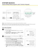
Keypad Interface
FRI 2: 52 PM
1 2 3 4
5 6 7 8
Power LED
Armed LED
32-Character Display
Select Keys
CommandBack Arrow
9 0 CMD
JONES RESIDENCE
Panic Keys
Backlit Logo
and Proximity
Antenna
A
C
B
D
F
E
G
I
H
J
L
K
V
X
W
S
U
T
P
R
Q
M
O
N
Y
Z
E
N
T
E
R
B
A
C
K
Figure 6: 7000 Series LCD Keypad

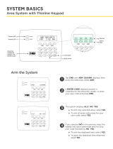
13
Keypad Interface
ABC SECURITY
FRI 2: 52 PM
1 2 3 4
5 6 7 8
Power LED
Armed LED
32-Character Display
Select Keys
Command
Back Arrow
9 0 CMD
A
C
B
D
F
E
G
I
H
J
L
K
V
X
W
S
U
T
P
R
Q
M
O
N
Y
Z
E
N
T
E
R
B
A
C
K
Figure 7: Thinline 7100 Series LCD Keypad

14
Entering Alpha Characters
To enter an alpha character, press the number
key that has the desired letter below it. The
keypad display shows the number on that key.
To change the number to a letter, press the top
row select key that corresponds to the letter
location under the key. See Figure 8.
Entering Non-Alphanumeric Characters
Each key has a non-alpha special character
that is not shown on the keypad. Non-
alphanumeric characters are entered into the
keypad the same way as alphanumeric characters.
See Figure 9.
First Letter
Second Letter
Third Letter
Special Character
A B C (
Figure 8: Entering Alpha Characters
1 2 3 4
9 0 CMD
5 6 7 8
A
(
C
B
D
)
F
E
G
!
I
H
J
?
L
K
V
,
X
W
S
$
U
T
P
&
R
Q
M
/
O
N
Y
'
(space)
Z
-
#
*
.
Figure 9: Entering
Non-Alphanumeric Characters
Keypad Interface

15
Panic Key Options
2-Button Panic Keys
All keypads oer a panic key function that allows users to send panic, emergency,
or fire reports to the central station in an emergency. Enable the panic key function
in the keypad user menu. Place the supplied icon stickers below the top row select
keys. The user must press and hold the two select keys for two seconds until a beep
is heard.
Panic (left two select keys)—Zone 19 + Device Address
Emergency Non-Medical (center two select keys)—Zone 29 + Device Address
Fire (right two select keys)—Zone 39 + Device Address
7/0 Panic Keys
All keypads allow the user to initiate a panic alarm by pressing the 7 and 0 (zero)
keys at the same time for one-half (1/2) second. Enable the 7/0 Panic function in
Installer Options. When enabled, all keypads send a Zone Short message to the panel
for the first zone of the keypad address. When the keys are released, a Zone Restore
message can be sent from the initiating keypad. To produce a panic alarm, program
the first zone of the keypad address as a panic type (PN) in panel programming.
Place a 1k Ohm end-of-line (EOL) resistor, DMP Model 311, across the white/brown
pair of zone wires on models 7070/A, 7073/A, 7170, and 7173. A Zone Restore
message sends when the keys are released. The 1k Ohm EOL resistor is not required on
7060/A, 7063/A, 7160, and 7163 keypads.
Keypad Interface

16
ACCESS THE USER OPTIONS MENU
To access the Options menu,
press and hold the back arrow and CMD keys for two seconds.
Press CMD to advance through the menu options.
Backlighting Brightness
Adjust the LCD display brightness level, power and armed LEDs, the green keyboard, and the
logo backlighting. At SET BRIGHTNESS, use the left select key to decrease the brightness and
the right select key to increase the brightness. If the brightness level is lowered, it reverts to
maximum intensity whenever a key is pressed. If no keys are pressed, and the speaker has not
sounded for 30 seconds, the user-selected brightness level restores.
Internal Speaker Tone
Adjust the keypad internal speaker tone. At SET TONE, use the left select key to decrease the
tone and the right select key to increase the tone.
Internal Volume Level
Adjust the keypad internal speaker volume for key presses and entry delay tone conditions.
During alarm and trouble conditions, the volume is always at maximum level. At SET VOLUME
LEVEL, use the left select key to decrease the volume and the right select key to increase the
volume.
Model Number
The keypad displays the keypad model number, firmware version, and date. The user cannot
change this information.
Keypad Address
The keypad displays the current keypad address. The user cannot change this information.

17
ACCESS INSTALLER OPTIONS
Keypad Options and Keypad Diagnostic menus allow install and service technicians to
configure and test keypad operation. To access the installer options:
1. Hold down the back arrow and CMD keys for two seconds.
2. At SET BRIGHTNESS, enter 3577 (INST) and press CMD.
The display changes to KPD OPT KPD DIAG and STOP. The Keypad Options menu allows
you to set the keypad address, select Supervised or Unsupervised mode, change the
default keypad message, selectively enable the 2-button Panic keys, Bypass, REX, and set
entry card options.
All programming options display on all keypads. However, actual operation for some
programming options is restricted to the appropriate model.
Programming Keypad Options
Keypad Options (KPD OPT)
To program keypad options, press KPD OPT.
Current Keypad Address
Set the current keypad address from 01 to 08 for
XT30/XT50/XR150 Series panels or 01 to 16 for XR550
Series panels. The default address is set at 01. To change
the current address, press any select key and enter the new
address. It is not necessary to enter a leading zero for
addresses 01 to 09.
KPD KPD
OPT DIAG STOP
CURRENT KEYPAD
ADDRESS: 01

18
Keypad Mode
Configure the KEYPAD MODE for supervised or
unsupervised operation. Keypads with programmed zones
must be supervised and cannot share an address with
other keypads. Unsupervised keypads can operate together
sharing the same address. Zones cannot be used on
unsupervised keypads. To change the current setting, press
the select key under SUP or UNSUP. An asterisk appears
next to the selected option.
Unsupervised addresses cannot be used when Device
Fail Output has a programmed value other than zero.
Default Keypad Message
Enter a DEFAULT KPD MSG of up to sixteen characters to
appear at the top of the keypad display. Press any select
key to clear the current message and enter a new custom
display.
Arm Panic Keys
Use this option to configure the top row select key as
as two button panic keys. To enable or disable a panic
option, press the select key under the appropriate name:
PN (panic), EM (emergency), and FI (fire). Once the panic
option is enabled, an asterisk displays next to the selected
option(s).
KEYPAD MODE:
SUP * UNSUP
DEFAULT KPD MSG:
ARM PANIC KEYS:
*PN *EM *FI
Installer Options
/