631500193INS
Revised: July 2, 2003
EIMI Cornelius Inc., 2003
IMI CORNELIUS INC g One Cornelius Place g Anoka, MN 55303-6234
Telephone (800) 238-3600 Facsimile (763) 422-3246
INSTALLATION INSTRUCTIONS
WATER BOOSTER KIT 631500193
TO THE USERS OF THIS MANUAL
This manual is a guide for installing this equipment. This unit must be installed and serviced by qualified service
person. This unit contains no user serviceable parts.
UNIT DESCRIPTION
The water booster is part of back room package and is installed either on top of the existing back room panel or
on the wall next to the back room stand. The purpose of the unit is to boost the potable water through the filter
system to maintain constant pressure throughout the beverage equipment in a restaurant. The water pump has
a liquid check valve on its outlet to prevent the back flow of water. A pressure switch is used to regulate the wa-
ter pressure throughout the system. A water booster tank is used to store water under pressure. A surge tank is
also a storage for filtered water and to absorb water pressure spikes in the system.
UNPACKING
Unpack LOOSE–SHIPPED PARTS. Make sure items are present and in good condition.
Table 1. Loose-Shipped Parts
Item
No. Part No. Name
Qty.
1 8871 Barbed Fitting 2
2 309852000 Clamp, Oetiker# 17.0 4
3 1992 End Cap, Square 2
4 1986 Connector Plastic 2
5 320940000 Screw #10 3
6 8865 Bracket, Front 1
7 631500193INS Installation Sheet 1
8 560001440 Bracket, Wall Mount 2
9 8987 Wood Screw 6
IDENTIFICATION OF LOOSE SHIPPED PARTS
1. Tapered Gasket, Black (item NO TAG) used to seal connection when connecting line from surge tank to
manifold on the back room panel.
2. Barbed Fitting (item 1) used to replace the flare fittings on connections B and C of back room panel filters
so that the 3/8” line can be inserted into the barbed fittings.

2631500193INS
3. Oetiker Clamps (item 2) used to clamp the tubing onto barbed fittings on connections B and C.
4. Square end cap (item 3) used to seal the bottom of the frame if the unit is installed on the wall. Used for
back room stand applications only.
5. Connector plastic (item 4) used to connect the unit onto the back room panel frame if the unit is installed
onto the back room panel frame.
6. Screw #10 (item 5) used to attach front bracket (item 6) and the uprights of the unit onto the back room
panel on both sides.
7. Front bracket (item 6) used to support the front part of the unit onto the back room panel.
8. Wall mount bracket (item 8) used to hang the unit on the wall, on back room stand applications only.
9. Wood screw (item 9) used to fasten the brackets (item 8) on the wall.
SELECTING LOCATION
CAUTION: This unit must not be installed or used outdoors where it will be exposed to the
elements.
Locate the unit on the back room panel of on a wall along stand close to properly grounded electrical outlet with
proper electrical requirements fused at 15–amps (slow–blow). For accessibility, the electrical outlet must not be
located behind the unit.
Locate the unit close to the back room stand so that the water pressure will not be affected by pressure drop
thought the line. Water lines from back room panel or stand should be 3/8” I.D. (minimum), food-grade plastic.
WIRING DIAGRAM

3
631500193INS
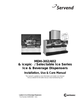
Two methods of installation:
A: On Back Room Panel
Support
Bracket
shipped
loose
A
B
C
Indicates Field Connection
Connect line
here
Connect
line
here
Remove
square
plugs
Connect line
here
B
C
B: On Wall
1.) Mounting Water Booster Brackets
The panel attaches to the wall with the two brackets (item 8) supplied. The bracket must be attached to wall
studs with the 3” dry wall screws (item 9) provided. The width of the panel will accommodate wall stud spacing
of 16 or 24 inches on center.
Must be Level
Mounting Brackets
16I or 24I on center
15” Min.
Ceiling
Wall Studs

4631500193INS
2.) Water Pressure Booster Placement
After brackets are mounted on the wall as shown, the shelf can be lifted into place. Lifting of the shelf will re-
quire 2 persons.
After the panel is in place drill a hole into the frame using the hole in the bracket as a guide. Secure shelf to the
brackets. Only one screw is needed. Connect all lines as indicated in the Connection Diagram. Use a gasket
(item NO TAG) on connection A and 4 clamps (item 3) on Connections B and C. Discard front bracket (item 6)
as it is not needed. Insert end cap (item 4) onto the bottom of the uprights.
Water Booster
Assembly
A
B
C

5
631500193INS
UNIT OPERATION
WARNING: The unit must be electrically grounded to avoid possible fatal electrical shock
or serious injury to the operator. The unit power cord is equipped with a three prong plug.
If a three hole (grounded) electrical outlet is not available, use a approved method to
ground the unit.
1. Connect the electrical power to the unit. The water pump will start and fill the tanks and filter system with
filtered water. The water pump will stop when the pressure is satisfied.
2. Check for water leaks and tighten any loose connections.
/