Page is loading ...

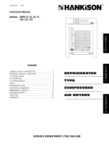
CRN SERIES
Models: CRN125, CRN150, CRN200, CRN250
SERVICE DEPARTMENT: (724) 746-1100
N SERIES
REFRIGERATED
COMPRESSED
AIR DRYERS
Contents
INSTRUCTION MANUAL
Models: CRN125, CRN150, CRN , C N250
®
7610.478.40D/0401037610.478.40D/0401037610.478.40D/040103
INTERNAL USE ONLY
7610.721.74 1/04
CA18-2-650, 1st Ed.
7610.478.40D/040103
INTERNAL USE ONLY
CRN300, CRN400, CRN500, CRN750
GENERAL SAFETY INFORMATION........................2
RECEIVING, MOVING, UNPACKING.......................2
1.0 INSTALLATION.....................................................3
2.0 OPERATION......................................................4-7
3.0 MAINTENANCE.................................................8-9
SIZING........................................................................10
ENGINEERING DATA...............................................11
ELECTRICAL SCHEMATICS...............................12-13
DIMENSIONS / WEIGHTS..................................14-15
TROUBLESHOOTING...........................................16-17
PARTS LIST ............................................................18
WARRANTY................................................................20

2
1. PRESSURIZED DEVICES:
This equipment is a pressure
containing device.
• Do not exceed maximum operating
pressure as shown on equipment serial
number tag.
• Make sure equipment is depressurized before
working on or disassembling it for service.
GENERAL SAFETY INFORMATION
2. ELECTRICAL:
This equipment requires electricity
to operate.
• Install equipment in compliance
with all applicable electrical codes.
• Standard equipment is supplied with electrical
enclosures not intended for installation in
hazardous environments.
• Disconnect power supply to equipment when
performing any electrical service work.
A. RECEIVING
This shipment has been thoroughly checked, packed
and inspected before leaving our plant. It was
received in good condition by the carrier and was so
acknowledged.
Check for Visible Loss or Damage. If this shipment
shows evidence of loss or damage at time of delivery
to you, insist that a notation of this loss or damage
be made on the delivery receipt by the carrier’s
agent.
B. UNPACKING
Check for Concealed Loss or Damage. When a
shipment has been delivered to you in apparent good
order, but concealed damage is found upon
unpacking, notify the carrier immediately and insist
on his agent inspecting the shipment. Concealed
damage claims are not our responsibility as our terms
are F.O.B. point of shipment.
C. MOVING
In moving or transporting dryer, do not tip dryer onto
its side.
D. STORAGE/SHUT DOWN
Dryer should not be stored outside (either
packed or unpacked) or exposed to the weather. Damage
to electrical and control components may result.
IMPORTANT: WATER-COOLED UNITS - If unit is shut down
below freezing temperatures, the water-cooled
condenser may freeze and cause permanent damage.
Condenser must be drained when the unit is shut down.
IMPORTANT: Do not store dryer in temperatures above
130°F, 54.4°C.
3. BREATHING AIR:
• Air treated by this equipment
may not be suitable for breathing
without further purification.
Refer to applicable standards and
specifications for the requirements for breathing
quality air.
RECEIVING, MOVING, AND UNPACKING

3
IMPORTANT:
READ PRIOR TO STARTING THIS EQUIPMENT
1.0 INSTALLATION
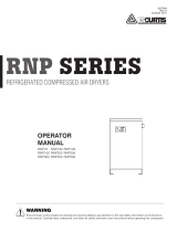
1.1 Location
A. For typical placement in a compressed air system, see
drawing.
B. Air compressor intake–Locate air compressor so that
contaminants potentially harmful to the dryer (e.g.
ammonia) are not drawn into the air system.
C. Dryer should be installed in a moderately heated, well
ventilated area. Avoid locations immediately adjacent
to cold exterior windows or walls, or adjacent to high
temperature ovens or boilers.
D. Clearances: Minimum requirements for free air flow
and service access
125 - 750 scfm models
Front 24 inches (610 mm)
Back 24 inches (610 mm)
Sides 12 inches (305 mm)
E. Standard units are designed to operate in ambients:
Air-cooled: 45 to 110°F (7 to 43°C).
Water-cooled: 45 to 130°F (7 to 54°C).
F. Installations in altitudes above 4500 feet (1370
meters) – Dryer is adjusted to operate in altitudes up
to 4500 feet (1370 meters). If dryer is installed in an
altitude above this, and has not been preset at the
factory for this altitude, contact manufacturer’s
Service Department.
NOTE: Outdoor installation–Standard units are designed
for indoor installation. Contact manufacturer if installing
outdoors.
1.2 Mounting
Mount the dryer on a level solid surface. Holes are
provided in the dryer base to permanently mount the
dryer to the floor.
1.3 Piping connections
A. Air Inlet - Connect compressed air line from air
source to air inlet. (Reference markings on dryer or,
see callout drawing on pages 14 and 15 for air in/
outlet connection locations)
Refer to Serial Number Tag for maximum
working pressure. Do not exceed dryer’s Maximum
Working Pressure.
NOTE:
Install dryer in air system at highest pressure possible
(e.g. before pressure reducing valves).
NOTE:
Install dryer at coolest compressed air temperature
possible. Maximum inlet compressed air temperature:
110°F (43°C). If inlet air exceeds this temperature, precool
the air with an aftercooler.
B. Air Outlet—Connect air outlet to downstream
air lines.
C. By-pass piping—
If servicing the dryer without interrupting the
air supply is desired, piping should include
inlet and outlet valves and an air by-pass valve.
D. Water-cooled models - cooling water inlet and outlet
1. Connect cooling water supply to cooling
water inlet.
2. Connect cooling water return line to cooling
water outlet connection.
NOTE: Strainer and water regulating valve are supplied on
water-cooled models. Also, it is recommended to add
water inlet/outlet temperature and pressure gauges to
the water piping.
Aftercooler
Separator
Dryer
Oil Removal
FilterCompressor
I - Controller Level 2
Separator/
Filter
Optional
Cold Coalescing Filter
Control
Panel
Timed Drain(s)
(NOT SHOWN)
Air
Connection
I - Controller Level 3
Separator/
Filter
Optional
Cold Coalescing Filter
Control
Panel
Air
Connection
Demand Drain(s)
(shown with Optional
Cold Coalescing Filter)

4
2.0 Operation
2.1 Minimum/Maximum operating conditions
A. Maximum inlet air pressure: refer to dryer serial
number tag
B. Minimum inlet air pressure: 30 psig (2.1 kgf/cm
2
)
C. Maximum inlet air temperature: 110°F (43°C)
D. Maximum ambient temperature:
Air-cooled models: 110°F (43°C)
Water-cooled models: 130°F (54°C)
E. Minimum ambient temperature: 45°F (7°C)
2.2 Start-up
IMPORTANT: Energize dryer disconnect switch (provided
by others, sec NEC) 24 hours before refrigeration
compressor is started! Never use the disconnect switch to
shut-down the dryer for a extended period of time
(except for repair). Failure to follow these instructions
may result in a non-warrantable compressor failure.
NOTE: It is recommended that dryer be started 15
minutes before compressed air flow begins.
NOTE: If there is no power to the control board for a
period of two weeks or more, it may return to the
default mode.
1. Confirm On/Off Switch is in the “Off” position.
2. On water-cooled models: after 24 hours, begin
cooling water flow.
3. Check for proper electrical voltage.
4. Energize dryer. Green power-on light will illuminate.
5. Slowly pressurize unit air side by opening inlet
isolation valve. Check for leaks.
6. After 15 minutes, open outlet isolation valve slowly.
7. Close air by-pass valve.
8. Identify I-Controller version Level on dryer
A. Models with I-Controller Level 2 - proceed to
Step 9.
B. For Models with I-Controller Level 3, see Section
2.7 for further instructions.
9. Toggle ON/OFF switch to the ON position.
1.4 Electrical connections
IMPORTANT: Use copper supply wires only.
A. Dryer is designed to operate on the
voltage, phase, and frequency listed
on the serial number tag.
B. If dryer is supplied with a cord and
plug, install in a
receptacle of proper voltage.
C. Electrical entry on larger dryers is through a hole in
the cabinet. It is located on the right side panel when
facing the front of the unit. Top right corner. Connect
power source to the terminal strip in the electrical
enclosure as shown on the electrical schematic
included with the dryer.
If optional disconnect is supplied, use entry hole in
disconnect enclosure.
NOTE: Refrigeration condensing unit is designed to run
continuously and should
NOT be wired to cycle on/off
with the air compressor.
1.5 Moisture separator
A. Separator (and Oil Removal Filter where applicable) has
an external drain which automatically discharges
collected condensate. It may be desirable to pipe the
condensate from the Automatic Drain outlet to a
suitable drain.
NOTE: Discharge is at system pressure. Drain
line should be anchored.
NOTE: Condensate may contain oil. Comply with
applicable laws concerning proper disposal.

5
1. For minimum inlet air pressures that fall between
column values, the setting for the lower pressure is
recommended. (i.e. select the 100 psi column values
for 124 psi inlet pressure listed in Table 1.)
Table 1 Timed drain illuminated LED Settings
2.3 Timer Drain
(Only Models with I-Controller Level 2)
NOTE: The Timer Drain LED level has been pre-
programmed at the factory for your specific dryer.
Programming is based upon a minimum of 100 psi
saturated inlet air pressure and maximum energy
efficiency. The drain open time is fixed at one second and
a small amount of air will be exhausted with each cycle.
Generally, no adjustment to the timer is required.
If water is present downstream of the
dryer, always verify that any condensate drains installed
upstream of the dryer are draining properly before
attempting to readjust the LED setting.
Inlet Pressure
75 100* 125 150 200 225
1253333 44
1502333 34
2002333 33
2502223 33
3001222 33
4001223 34
5001122 33
7501111 22
Flow (scfm)
Table 2 LED Legend
* Recommended and pre-programmed factory settings for each dryer. Assumes
CAGI ADF100 inlet conditions with 100°F ambient and 10°F air-cooled aftercooler
approach temperature.
Minutes
LED between
Illuminated Drain Cycles
1
st
1
2
nd
3
3
rd
5
4
th
10
5
th
20
6
th
30
7
th
40
8
th
50
9
th
60
33 F......................39 F
1 C.......................4 C
2.4 Timer Drain Programming Mode
1. Press the “Drain Interval Program” button (the
“Condensate Draining” LED will start to flash, and the
illuminated LED on the “Dew Point Temperature
Indicator” will identify the factory setting for “Minutes
Between Drain Cycles.” (See Table 1)
2. Press and release the “Drain Interval Selector” button
to sequence the “Minutes Between Drain Cycle LED’s”
from left to right until reaching your selection. The
“Red” LED is not used (Reference Table 2 for “Drain
Cycle Intervals”)
3. To initiate the new setting, press the “Drain Interval
Program” button (this will store the new setting and
exit the program).
4. Exiting the Program will cause the Timer Drain to
discharge and begin a new cycle.
NOTE: Failure to perform step 3 within 25 seconds of
completing step 2 will cause the unit to revert back to the
previous setting.
NOTE: In the event of a brief or extended period of
power loss, the unit will retain the existing program
setting and will begin a new cycle once power is
reapplied. Had drain been ready to drain before the loss
of power, the drain bowl’s capacity would prevent
downstream flooding. Condensate will drain completely
within a couple of cycles. (Manually pressing the “Push-to-
Test” button would drain bowl immediately)
2.5 Operating check points
Check the following on a periodic basis:
A. Green power on light is illuminated.
B. Dewpoint indicator is in green area.
C. Condensate is discharging from drain.
Condensate Draining
(Flashes in
programming
mode)
Drain Interval
Program
33
33
°F......................39
......................39
°F
1°C.......................4°C
Dew Point
Temperature
Indicator
Drain Interval
Selector
(LED illuminated
indicates drain
cycle setting)
2. Where the dryer is consistently operating at less
than maximum capacity, it may be possible to
increase the LED set point to minimize air loss.
Discretionary adjustments to the dryer should only
be made on a hot, humid day when the maximum
expected air load is flowing through the dryer.
Failure to do so may prevent the condensate from
draining completely when operating under peak
load conditions.
I - Controller Level 2 - Standard
33
33
°F......................39°F
1°C.......................4°C
On/Off
Switch
Switch Legend
Power On
Light
Compressor
On Light
Dew Point
Temperature
Indicator
Drain
Push-to-Test
Condensate
Draining

6
2.7 I-Controller Level 3 –
(Optional on 200-750 scfm models)
Dryers upgraded with the optional I-Controller Level 3
include text messaging on the Vacuum Fluorescent Text
Display (VFTD), Alert/Alarm condition display panel
warning lights, process diagram LED indicator lights,
Demand Operated Condensate Drains(s) and SURE-SAVE
Heat Reliever as standard features.
Programming, Start-up and, Operating Instructions
Dryers are pre-programmed in accordance with the
manufacturers recommendations. Programming details
are listed within Table 1.
NOTES:
a) Programming can be accomplished while dryer is in
either the ON or OFF mode.
b) The OPERATION sub-directory list automatically scrolls
sequentially every 3 seconds. Press the (ENTER) key
repeatedly to scroll manually.
2.6 SURE-SAVE Cooling Injection
(Optional: 125-750 scfm model)
Standard: Models with I-C Level 3 Controller
Dryers outfitted with the SURE-SAVE option automatically
protect the refrigeration compressor from damage due
to excessive inlet air temperatures. A temperature sensor
continually monitors the compressor operating
conditions. If the temperature exceeds standard design
conditions, the SURE-SAVE cooling injection valve
automatically redirects cooling energy back to the suction
side. This allows continued operation with an elevated
pressure dew point rather than initiate a high
temperature shutdown. To protect the dryer, high inlet
air temperature shutdown will occur if inlet air
temperature exceeds 140°F.
VFTD Text Viewing Instructions
1. Press (Right-Arrow) or (Left-Arrow) to select from the
following Main Menu items: OPERATION,
MAINTENANCE, CONFIGURATION, UNIT SET UP
2. Press the (ENTER) key to access the sub-directory of
the Main Menu item of your choice.
NOTE: Press (ENTER) repeatedly to sequence through the
sub-directory text displays listed in table 1.
Operation Maintenance Configuration Unit Set Up
(view) (view) (programmable*) (factory (programmable*) (factory
setting) setting)
Dew Point Hours Gardner Denver n/a *Dew Point Set Pt 50°F/
Temp (°F/°C) to Service IC3 Ver (xxx) (50°F-95°F) 10°C
Ambient Temp Total *Set Language Eng., English *Ambient Set Pt 105°F/
(°F/°C) Hours Spanish, French ( 95°F-122°F) 41°C
Inlet Air Temp *Set Date Current *Inlet Air Set Pt 105°F/
(°F/°C) MO/DA/YR (95°F-140°F) 41°C
HR:MIN:SEC *Set Time Eastern *Service Interval 2000
MO/DA/YR HR:MIN:SEC Standard (0-4000 Hours) Hours
Dryer *Set Temp
ON (OFF) °F/°CF
Table 1
Vacuum
Fluorescent
Text Display
On
Switch
Off
Switch
Gauge
LED’s
Temperature
LED’s
Drain LED
Alarm Light
Warning/
Maintenance
Light
Reset
Compressor
Running Light
Drain Push-
to-Test
Power-on
Light
Programming
Buttons
I-Controller Level 3 - (Optional)
Programming Instructions (CONFIGURATION or UNIT
SET UP modes only)
1. Press (Right-Arrow) or (Left-Arrow) to select from the
following Main Menu items: OPERATION,
MAINTENANCE, CONFIGURATION, UNIT SET UP
2. Press the (ENTER) key to access the sub-directory of
the Main Menu item of your choice.
Note: Press (ENTER) repeatedly to sequence through
the sub-directory text displays as listed in table 1.
3. To reprogram your selection, press and release and/
or hold down the (+) or (-) key until you reach the
desired value
4. Press (ENTER) to accept the new setting.
NOTES:
a) Display will automatically return to normal operating
mode 30 seconds after last key is depressed.
b) Programming automatically reverts back to prior
settings in 30 seconds if (ENTER) is not depressed.
Start-up Instructions - I-Controller Level 3 (Continued
from Section 2.2)
1. Energize dryer.
A. Green POWER ON light will illuminate.
B. VFTD will read “GARDNER DENVER IC3 (version)”
Text display automatically sequences at 3 second
intervals in the following order:
a. AMBIENT AIR TEMP (°F or °C)
b. INLET AIR TEMP (°F or °C)
c. TIME/DATE (hours: minutes: seconds/month/
day/year)
d. DRYER OFF or ON (status)
e. DEW POINT TEMP (°F or °C)
C. LEDs – The GREEN Thermometer LEDs on the
Process Diagram will illuminate when the
corresponding temperature point is shown in the
VFTD.
2. Depress Green (START) button.
A. The Green “COMPRESSOR ON” panel light
and process diagram LED will illuminate.
NOTE: If dryer is started while “DRYER OFF” is displayed
within the VFTD, it will change to “DRYER ON” with the
next display rotation.
Programming Buttons
Right ArrowLeft Arrow
Enter

7
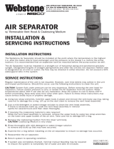
2.8 Electronic Demand Drain – I-Controller Level 3
A. An automatic electric demand drain (EDD)
discharges condensate removed by the
separator.
B. All standard I-Controller Level 3 models are supplied
with one EDD. Models with the additional (optional)
cold coalescing filter are supplied with a second EDD.
C. For manual draining, convenient dryer
depressurization, and EDD service, a three-way valve
at the bottom of the moisture separator and before
the EDD is installed. For manual draining, turn the
valve handle so it is in a horizontal position. Open the
petcock on the side of the dryer base pan to
discharge the condensate or to depressurize the
dryer if it has been by-passed. The petcock can be left
in a throttled (partially opened) position should there
be a problem with EDD.
The drains are piped to the right side panel, bottom
right corner of the unit.
Discharge is at system pressure. Drain line
should be anchored.
NOTE: Condensate may contain oil. Comply with
applicable laws concerning proper disposal.
D. Verify that isolation valves are open. If the drain fails
to discharge after the valve is energized, the
electronic control circuit will repeatedly energize the
valve in an attempt to clear the discharge port. If,
after 60 seconds, the drain still fails to discharge, the
control circuit then switches to the alarm mode. In
this mode the valve is de-energized and the red alarm
light is activated on the drain and control panel and
the green LED on the process diagram. The valve is
then automatically energized every 4 minutes for 5
seconds. Check the drain operation. Push drain
(push-to-test) button on the I-Controller level 3
control panel to energize drain. A flow of condensate
and/or air should be present at the drain outlet. The
alarm mode automatically clears after the drain
returns to normal operation.
E. Condensate enters the reservoir (1) through the inlet
port. When the condensate level in the reservoir
covers the capacitance sensor, an electronic signal is
sent to the solid state countdown processor. The
processor delays the opening of the solenoid valve
for a given period of time. Once the time has
elapsed, the solid state processor transmits
information to energize the coil in the solenoid valve
(2).The magnetic force of the coil causes the solenoid
core (3) to move, closing the pilot air supply line and
opening the pilot air exhaust line. After the pilot air
above the diaphragm (4) is vented, pressure in the
reservoir opens the discharge port and forces the
condensate through the discharge port and outlet
piping.
1
2
3
4
2.9 Operating Instructions – I-Controller Level 3
1. Check the following on a periodic basis:
a. Power-on light glows (green) indicating power to
the dryer
b. Compressor-on light glows (green) indicating the
refrigeration compressor is operating
c. VFTD is automatically scrolling every 3 seconds
through OPERATION mode readings and settings
d. Warning/Maintenance Alert light (yellow) is NOT
flashing
e. Alarm light (red) is NOT flashing
f. Condensate is draining
2. ALARM/ALERT Fault Condition Activation
(See wiring diagram for N/O contact location.)
Upon activation, text identifying the Fault will be
displayed on the VFTD. An Audible Alarm will sound, a
Flashing Panel light (Warning/Yellow or, Alarm/Red)
and, a Flashing Process Diagram LED (Green or Red)
combine to indicate the fault condition. Where
applicable (see table 2 on page 17) a normally open
(N/O) circuit will activate a customer supplied remote
alarm.
NOTE: If yellow Alert light or, red Alarm light ARE flashing,
see fault condition identified in VFTD window. Reference
the condition in the Troubleshooting Guide on page 17.
3. AUTO RESTART Function
Software programming allows the dryer to
automatically restart in the event of an interruption
of power. Consult factory for details.
4. REMOTE START/STOP Function
Software programming allows the dryer to be
stopped and started by a remotely controlled signal.
Consult factory for details.
5. DOWNLOADABLE MEMORY Function
Software programming allows the dryer to store the
last 10 alarm related events. Output command
delivers the events complete with the date, time and,
fault condition. Consult factory for details.
6. RS-232 & RS-485 Communications Capable
Dedicated pin arrangement is used to monitor dryer
operation from a host computer. Consult factory for
details.

8
3.2 Moisture Separator/Oil Removal Filter
NOTE: Prepackaged maintenance kits are available that
include all necessary filter and timed drain valve
components. Maintain maximum performance and
efficiency with Genuine Parts. See page 18 for ordering
information.
When to replace the Separator/Filters
Replace filter element when pressure drop across
dryer is excessive or annually.
Dryers have the option of one or two stages of
filtration. The directions for servicing either filter is
identical.
When removing liquids at rated flow conditions, an
increase in pressure drop will occur as the separator/
filter elements become loaded with solid particles.
Procedure for Separator / Filter Element
Replacement 125-500 scfm models
THIS FILTER IS A PRESSURE CONTAINING
DEVICE. DEPRESSURIZE BEFORE SERVICING. If filter has not
been depressurized before disassembly, an audible alarm
will sound when the bowl begins to be removed from the
head. If this occurs, stop disassembly, isolate and
completely depressurize filter before proceeding.
200 thru 500 scfm models
Separator Element
or Optional Oil Removal
Element
Wave
Spring
Bowl
O-ring
Timer Drain Valve - Standard
3.0 MAINTENANCE
3.1 Condenser coil
A. Air-cooled - clean off accumulated dust and dirt
monthly or as necessary in dirty environments.
B. Water-cooled - clean strainer monthly, more often if
required. Shut off water, remove small plug to relieve
pressure, then remove large plug to remove strainer.
Clean strainer and replace.
125 thru 150 scfm Models
Separator Element or
Optional Oil Removal Element
Timer Drain Valve - Standard with I-Controller Level 2
Demand Drain - I-Controller Level 3 Only
1. Isolate dryer (close inlet and outlet valves if installed)
or shut off air supply.
2. Depressurize filter by slowly opening manual drain
by-pass valve.
3. Remove bowl
a. For 125 through 150 scfm models - bayonet
mount - push bowl up, turn bowl 1/8th turn to
your left, and pull bowl straight down
b. For 200 through 500 scfm models - threaded
bowls - unscrew bowl from head using hand,
strap wrench or C spanner.
4. Clean filter bowl
5. Replace moisture separator element.
a. Replacing complete Grade B element.
1) Pull off old element and discard
2) Make certain o-rings on male of replacement
element adaptor are in place and push
element into filter head.
NOTE: Do not handle Oil Removal Filter elements by
outside foam cover. Handle by bottom end cap only.
6. After making certain that o-ring inside top of bowl
(and on bayonet mount heads, wave spring) are in
place, reassemble bowl to head.
NOTE: Make certain o-ring is generously lubricated. (Use
lubricant provided)
NOTE: Wave spring ends should be pointed down to
prevent the wave spring from interfering with
reassembly.

9
3.3 Check separator daily to be sure automatic drain
is discharging.
NOTE: Units with two stage filtration have two sets of
drains.
3.4 Blow down separator weekly by pushing test
button on control panel.
3.5 Rebuild drain mechanism annually.
To facilitate service, maintenance kits are available.
See page 18.
Gasket
Coupling
Half
Grooved Shell
Grooved Upper
Shell Cap
Bolts
3 & 4
Depressurize the unit before servicing.
Failure to do this may result in injury. The unit must be
depressurized before the couplings are removed.
a. For normal element replacement, the separator
shell assembly must be removed. Remove the
insulation from the upper shell cap.
Check to be sure the unit is depressurized.
b. Release the condensate drain line quick
disconnect fitting.
c. Remove the two bolts on the upper and lower
shell couplings (3). Remove the couplings,
exposing the gaskets.
d. Slide the upper piping gasket down and the lower
piping gasket up on to the separator shell (1).
e. Slide the separator shell assembly out.
f. Remove the element retainer plate (5).
g. Remove the separator/filter element (6) by simply
pulling and lifting them out of the element
sealing port (1a). Discard the old element.
h. Inspect the inside surfaces of the separator shell
(1), the element seal plate, and sealing port (1a).
i. Lubricate the new separator/filter element o-ring
seals according to the element package
instructions.
j. Install the new element by carefully pushing it in
to the element sealing port (1a).
k. Reinstall the element retainer plate (5).
l. Inspect the upper and lower shell cap gaskets and
apply a thin coat of lubricant to the outside and
to the sealing lips of these gaskets.
m. Slide the separator shell assembly back in.
n. Slide the gaskets into position, centering them
between the coupling grooves.
o. Replace the upper and lower shell cap couplings
(3). Tighten the bolts evenly and alternately.
Uneven tightening may cause the gaskets
to pinch and not seal! Gasket damage may result!
p. Reinstall the insulation.
q. Slowly repressurize the dryer.
r. Inspect the assembly for air leaks.
NOTE: Further disassembly is not required or
recommended for maintenance.
s. Disassemble condensate drain valve(s).
t. Rebuild drain valves using Genuine Parts. See page
18 for ordering information.
750 scfm model
4
2
3
5
1
6
1A
3
4
2
3
5
1
6
1A
3
Timer Drain - Standard - I-Controller Level 2
Demand Drain - I-Controller Level 3 Only
NOTE: Threaded bowl to head connection, generously
lubricate threads with a high grade/temperate lubricant
150 °F, 66°C. (Use lubricant provided).
7. Disassemble condensate drain valve(s).
8. Rebuild drain valves using Genuine Parts. See page 18
for ordering information.
Procedure for Separator / Filter Element
Replacement 750 scfm model
The separator/filter assembly consists of: the
separator shell assembly 1, the upper shell cap 2, the
upper shell coupling and gasket 3, the upper piping
coupling and gasket 4, the element retainer plate 5,
and the separator/filter element 6.

10
COOLING MEDIUM*
AMBIENT
TEMPERATURE MULTIPLIER
°F °C
80 27 1.12
90 32 1.06
100 38 1.00
110 43 0.94
INLET COMPRESSED AIR CONDITIONS
INLET INLET TEMPERATURES
PRESSURES 80°F90°F 100°F 110°F
psig kgf/cm
2
27°C32°C38°C 43°C
50 3.5 1.35 1.05 0.84 0.69
80 5.6 1.50 1.17 0.95 0.79
100 7.0 1.55 1.23 1.00 0.82
125 8.8 1.63 1.31 1.07 0.91
150 10.5 1.70 1.37 1.13 0.95
175 12.3 1.75 1.42 1.18 0.99
200 14.0 1.80 1.47 1.22 1.03
SIZING
Determining dryer capacity at actual operating conditions
To determine the maximum inlet flow capacity of a dryer
at various operating conditions, multiply the rated capacity
from Table 1 by the multipliers shown in Table 2.
Example: How many scfm can an air-cooled 750 scfm
model handle when compressed air to be dried is at 200
psig and 100°F; ambient air temperature is 80°F; and a
38°F dew point temperature is desired?
Answer: 750 x 1.22 x 1.12 x 1.0 = 1,025 scfm.
TABLE 2
Air capacity correction factors (Multipliers)
MODELS 125 150 200 250 300 400 500 750
Rated capacity 60 Hz 125 150 200 250 300 400 500 750
of air-cooled 50 Hz 104 125 167 208 250 333 417 625
models (scfm)
TABLE 1
Rated capacity (scfm) and pressure drop @ 100 psig inlet
pressure, 100°F inlet temperature, and 100°F ambient
temperature
*Air-cooled models; water-cooled models use 1.15 multiplier if cooling
water is below 35°C, 95°F.
OUTLET DEWPOINT
DEWPOINT
TEMPERATURE MULTIPLIER
°F °C
38 3 1.0
45 7 1.2
50 10 1.3

11
ENGINEERING DATA
MINIMUM - MAXIMUM OPERATING CONDITIONS
Min.-Max. Inlet Air Pressure (compressed air at inlet to dryer) Minimum 30 psig (2.1 kgf/cm
2
) Maximum (1)
Max. Inlet Air Temperature (compressed air at inlet to dryer) 110°F (43°C)
Min.-Max. Ambient Temperature
Air-cooled 45°F (7°C) - 110°F (43°C)
Water-cooled 45°F (7°C) - 130°F (54°C)
REFRIGERATION SYSTEM DATA
Compressor Type Hermetic - Non-Cycling
Refrigeration Compressor Horsepower 3/4 1 1-1/2 2 3
BTU/HR - Refrigeration Only @ 35°F Evaporator & 100°F Ambient 60/50 Hz 6020 / 5017 8660 / 7217 15600 / 13000 17400 / 14500 26700 / 22250
Outlet Air Temperature (nominal at rated conditions) 85°F (29°C)
Refrigerant Type R-134a
Refrigerant Charge See dryer serial number tag
Suction Pressure Setting (controlled by hot gas by-pass valve) 31.5 31.5 31.5 31.5 31.5
Compressor Control Ranges (psig) (out-in) High - 281-190 281-190 281-190 281-190
Low - 24-34 24-34 24-34 24-34
Condenser Fan Switch Setting (in-out)(psig) Fan 1 110-70 113-78 113-78 113-78 113-78
(air-cooled models) Fan 2 - - - 183-124 183-124
Air Flow Across Condenser (cfm) (air-cooled models) 60/50 Hz 530 / 440 672 / 560 1093 / 911 2650 / 2208 2650 / 2208
Condenser Cooling Water Requirements (water-cooled models)
Recommended Water Pressure (psig) 40 Min. - 120 Max*.
Gallons Per Minute Of Flow Required With 85°F Cooling Water 60/50 Hz 2.2 / 1.8*** 2.9/2.4 4.8/4.0 5.8/4.8 12/10
Inlet Water Connection 1/2” Female
ELECTRICAL
Nominal Voltage 115/1/60 208-230/3/60 208-230/3/60 208-230/3/60 208-230/3/60
Max.- Min. voltage 127-104 253-187 253-187 253-187 253-187
Rated Load Amps** 14.7 8.4 11.5 13.6 22.9
Locked Rotor Amps** 66.3 51 65.5 75 90
Minimum Circuit Ampacity 18.3 10.5 16.9 17.1 31.7
Branch Circuit Fuse Size (amps) 24 15 20 25 45
Watts @ 35°F Evaporator & 100°F Ambient 1060 1335 1940 2620 3600
Resistance (Ohms) Three phase (Total) - 1.77 1.256 1.058 0.853
Single phase Start C/S 3.15 - - - -
Run C/R 0.416 - - - -
Nominal Voltage 208-230/1/60 460/3/60 460/3/60 460/3/60 460/3/60
Max. - Min. Voltage 253-198 506-414 506-414 506-414 506-414
Rated Load Amps** 8.3 4.0 4.9 6.2 11
Locked Rotor Amps** 33.5 25 33 40 45
Minimum Circuit Ampacity 10.5 5.2 9.2 9.6 15.6
Branch Circuit Fuse Size (amps) 15 15 15 15 20
Watts @ 35°F Evaporator & 100°F Ambient 1060 1335 1940 2620 3600
Resistance (ohms) Three phase (Total) 7.92 - 7.44 4.95 4.11 0.853
Single phase Start C/S 7.92 - - - -
Run C/R 1.55 - - - -
Nominal Voltage 220-240/1/50 380-420/3/50 380-420/3/50 380-420/3/50 380-420/3/50
Max. - Min. Voltage 264-198 462-342 462-342 462-342 462-342
Rated Load Amps** 7.6 4.0 4.9 5.7 9.9
Locked Rotor Amps** 53.0 25 33 45 45
Minimum Circuit Ampacity 9.9 5.2 9.2 9.6 15.6
Branch Circuit Fuse Size (amps) 15 15 15 15 20
Watts @ 35°F Evaporator & 100°F Ambient 930 1068 1552 2096 3030
Resistance (ohms) Three phase (Total) - - 7.44 4.95 4.11 0.853
Single phase Start C/S 10.49 - - - -
Run C/R 1.8 - - - -
Nominal Voltage 220-240/1/50 575/3/60 575/3/60 575/3/60 575/3/60
Max. - Min. Voltage 264-198 632-518 632-518 632-518 632-518
Rated Load Amps** 7.6 3.2 3.9 4.6 7.9
Locked Rotor Amps** 53.0 25 33 40 45
Minimum Circuit Ampacity 9.9 4.2 7.4 7.7 12.8
Branch Circuit Fuse Size (amps) 15 15 15 15 15
Watts @ 35°F Evaporator & 100°F Ambient 930 1335 1940 2620 3600
Resistance (ohms) Three phase (Total) - 7.44 4.95 4.11 0.853
Single phase Start C/S 10.49 - - - -
Run C/R 1.8 - - - -
MODELS 125 & 150 200 250, 300 & 400 500 & 600 750
(1) Maximum Inlet Pressure - 232 psig (16.3 kgf/cm
2
) I - Controller Level 2
200 psig (14 kgf/cm
2
) I - Controller Level 3
* Allows continued operation with some restriction in the water strainer
** Air-cooled models only
*** 150 scfm model only

12
Electrical Schematics
Models 125, & 150 - 115V/60 Hz (I-Controller Level 2)
Model 125 & 150 - 208-230V/60 Hz; 220-240V/50 Hz (I-Controller Level 2)
Legend
SW - ON/OFF Switch 2FU - Primary Fuse
CON - Contactor 3FU - Primary Fuse
TR1 - Transformer Control 1FU - Secondary Fuse
MTR - Compressor DRN1 - Drain Solenoid - Standard
1FM - Fan Motor DRN2 - Drain Solenoid (Oil Coalescing Option)
2FM - Fan Motor (RNC300-750 Only) EDD1 - Electric Demand Drain
1FPS - Fan Pressure Switch Fan 1 EDD2 - Electric Demand Drain (Oil Coalescing Option)
2FPS - Fan Pressure Switch Fan 2 (RNC300-750 Only) TC1/TC2/TC3 - Temperature Sensor, Thermistor
LPCO - Low Pressure Cutout Switch CAP - Start Capacitor
HPCO - High Pressure Cutout Switch TB - Terminal Block
SSMP - Solid State Motor Protection SR - StartRelay
HTR - Crankcase Heater FM - Fan Motor
OL - Overload
CUSTOMER CONNECTION/
POWER CORD
SR
CON PE
CON PE
BLU
BLU
1
2
GROUND
DRN1
DRN2
1
L
N
FM
2
FM
FM
FPS
M
R
CON N
NEUTRAL
LINE
BRN
2
BRN
CON L1
1
CON
L1
2
N
N
N
2
FM
1
L
L
SW
1
C
L3
2
CAP
SR
S
S
MTR
OL
1
3
NOT USED
ON WATER-COOLED UNITS
COIL
COMP
ON
DRAIN
NEUTRAL
DRAIN
TC1
TB 5
N
L
P
IC2 OPTION
BOARD ADDITION AND DRAINS
(SEE OPTION NOTES)
CUSTOMER CONNECTION/
POWER CORD
SW
FM
SR
CAP
FPS
MTR
C
R
M
S
3
1
OL
SR
S
L3
TB 1
TB PE
TB 2
TB 4
TB 3
TB PE
DRN1
DRN2
BRN
BRN
2
L
N
2
FM
1
1
FM
FM
2
2
1
N
L
2
1
BLU
BLU
L
N
1
LINE
NEUTRAL
GROUND
2
NOT USED
ON WATER-COOLED UNITS
L
N
P
DRAIN
DRAIN
NEUTRAL
COMP
ON
TB 5
TC1
Optional Notes:
1. IC2-Includes IC2 Instrument Panel and Timed Solenoid Drains.
2. IC3-Includes IC3 Control Panel and Demand Drains
3. DRN2-Optional Cold Coalescing Drain
4. 575-3-60 Supplied from equipment mounted transformer
5. Water-Cooled units: Fan Motor(s) and Fan Pressure Switch(es) are removed.

13
Models 200 thru 750 - 230-400-460-575V/3/50-60 Hz
(I-Controller Level 2)
Models 200 thru 750 - 230-400-460-575V/3/50-60 Hz
(I-Controller Level 3)
P4P1 P2 P3
FOR 575-3-60
380/420-3-50
(SEE DETAIL A)
230-3-60
460-3-60
24V
TC1
TC2
TC3
CON
COIL
P6P5 P7 P8 P9 P10
NO
P11
NC
C
P12
OPTIONAL
EDD2
ALARM
ALARM TEST
EDD1
TEST
CON
L1
L1
L1
T1
L1
TB
DRAIN ALARM
H
24 VAC
TB
TB
1
TB TB
2
3
TB
4
TB
5
HPCO
SSMP
LPCO
CONNECTION
CUSTOMER
PE
L3
L2
L1
575V
PE
L3
L2
H2
TB
PE
X4
X2
DETAIL "A"
(575V TRANSFORMER BANK)
X1
X3
460V
H4
PE
L3
H2
H1
H3
L2
L1
H4
H3
TO TB L3
TO TB PE
L3
TB
TO TB L2
L2
TO TB L1
L1
TRANSFORMER CONNECTION (TR1)
575V CONNECTION SHOWN. (H6, H1)
X3
X1
X2
X4
H1
PE
L3
L2
PE
L3
L2
FOR: USE TAPS:
208V H6 / H5
230V H6 / H4
460V H6 / H2
380-420V H6 / H3
2
X
6
H
4
5
H
H
2FU
TB
TB
9
A2
A1
INLET
TEMP
TB
TB
6
10
TB
11
SEPARATOR
TEMP
IC3 CONTROL PANEL
REMOTE
START/STOP
AMBIENT
TEMP
8
TB
9
TB
7
17
13
TB
TB
12
TB
14
DRAIN TESTPOWER ON
FAULT
15
POWER
16
MTR
TB
TB TB TB TB
4
3
L
3
1
4
6
5
L
N
2
65
N
1FU 6.25 AMP
2FU/3FU 230V-2 AMP
2FU/3FU 460/575V-1 AMP
X
1FU
F
TR1
H
2
3
H
1
GND
FUSE SIZES TR1:
3FU
TB
L2
L3
T2
T3
TB
1FPS
TB
2FPS
TB
TB
TB
TB
TB
TB
TB
1FM
2FM
RNC500-750
USED ON
CONNECTION
CUSTOMER
OPTIONAL POWER
DISCONNECT
N
N
HTR
L N
CUSTOMER
CONNECTION
CUSTOMER
CONNECTION
S
S
S
Electrical Schematics

14
DIMENSIONS/WEIGHTS
DimensionsDimensions
DimensionsDimensions
Dimensions
inchesinches
inchesinches
inches
ModelsModels
ModelsModels
Models
125125
125125
125
150150
150150
150
200200
200200
200
250250
250250
250
A 33-1/8 33-1/8 39-1/2 39-1/2
B 25-5/16 25-5/16 32-3/8 32-3/8
C 26 26 32-3/8 32-3/8
D 4-1/8 4-1/8 5-5/16 5-5/16
E 9-7/16 9-7/16 12-5/8 12-5/8
F 4-1/2 4-1/2 4 4
G 20-11/16 20-11/16 24-7/16 24-7/16
H 24-3/16 24-3/16 21-3/16 21-3/16
I 24 24 29-3/4 29-3/4
J 21-13/16 21-13/16 27-1/8 27-1/8
Inlet/Outlet
Connections 1 MPT 1 MPT 1-1/2 MPT 1-1/2 MPT
Weight lbs 229 244 410 410
Weight lbs with
Oil Removal Filter 237 252 423 423
125 thru 150 scfm models
200 thru 250 scfm models
TOP VIEW
FRONT VIEW RIGHT SIDE VIEW
TOP VIEW
FRONT VIEW RIGHT SIDE VIEW
C
I
J
B
A
F
E
D
G
H
C
J
B
A
F
G
H
E
D
AIR FLOW
AIR FLOW

15
DIMENSIONS/WEIGHTS
Dimensions
inches
Model 300 400 500 750
A 49 49 49 55-1/2
B 32-3/8 32-3/8 32-3/8 32-3/8
C 47-1/25 47-1/25 47-1/25 1-1/2
D 5-13/16 5-13/16 5-13/16 5-7/8
E 13-7/8 13-7/8 13-7/8 13-15/16
F 4 444
G 33-9/16 33-9/16 33-9/16 38-3/4
H 37-9/16 37-9/16 37-9/16 42-3/4
I 44-3/4 44-3/4 44-3/4 48-3/4
J 27-1/8 27-1/8 27-1/8 27-1/16
Inlet/Outlet
Connections 1-1/2 MPT 2 MPT 2-1/2 MPT 2-1/2 MPT
Weight lbs 631 672 701 968
Weight lbs with
Oil Removal Filter 644 704 733 1038
TOP VIEW FRONT VIEW RIGHT SIDE VIEW
300 thru 500 scfm models
750 scfm models
TOP VIEW FRONT VIEW
RIGHT SIDE VIEW
C
J
B
A
F
G
H
E
D
C
I
J
B
A
F
G
H
E
D
AIR FLOW
AIR FLOW

16
TROUBLESHOOTING GUIDE
SYMPTOM
A. Water downstream of dryer
B. High pressure drop across
dryer
C. Dew point indicator in red
area
D. Refrigeration system not
functioning properly
1. Power On light off
2. Compressor on light off
3. Refrigerant compressor
cycles on and off
POSSIBLE CAUSE(S)
1. Residual free moisture remaining
in downstream pipelines
2. Air by-pass system is open
3. Inlet and Outlet connections are
reversed
4. Temperatures surrounding air
lines downstream of dryer have
dropped below dryers dew point
rating
5. Excessive free moisture (bulk
liquid) at dryer inlet
6. Condensate not being automati-
cally drained
Drain mechanism is clogged or
inoperative.
Drain line is restricted or frozen.
Electric drains–timer not set to
allow for sufficient condensate
removal
7. Dryer overloaded resulting in
elevated dew point.
8. Refrigeration system not func-
tioning properly resulting in
elevated dew point.
1. Excessive air flow
2. Freezing of moisture in evapora-
tor because of refrigeration
system improperly functioning.
3. Separator or optional Oil Removal
filter element clogged.
1. Dryer overloaded resulting in high
air outlet temperature.
2. Refrigeration system not func-
tioning properly resulting in high
air outlet temperature.
3. Dryer is running with no load
a. Power failure
a. ON/OFF switch is “OFF”
b. Line disconnect switch open
c. Blown fuses, open breaker
d. Faulty wiring, loose terminals
a. High or low ambient conditions
b. Air-cooled models–Dirty, clogged
condenser fins, obstructed air
flow across condenser, or non
functioning fan motor or fan
control switch.
CORRECTIVE ACTION
Blow out system with dry air
Check valve positions
Check for correct connection
Insulate or heat trace air lines exposed to
low ambients or dry air to lower dew point
Install separator ahead of dryer
Replace drain mechanism if inoperative
Open drain line
Electric drains–reset time so that all liquid
is discharged
Check inlet air temperature and pressure,
flow rate (compressor capacity) and
ambient air or water temperature.
See D below
Check flow rate
See D below
Replace filter element(s).
See A 7
See D below
Light will go out when air flow is
established
Check power to unit
Turn switch “ON”
Close disconnect switch
Check for continuity
Have electrician check electrical connections
Check min./max. temperature ranges
Clean condenser and check for free air
flow, if problem persists contact qualified
refrigeration repairman or manufacturer’s
service department.

17
I - CONTROLLER LEVEL 3
Alert/Alarm Condition Indicators
TABLE 2
I-Controller Level 3 Alert/Alarm Fault Status Indicator Guide
Text Window Fault Condition Panel Lights Process Diagram LEDs* Audible Alarm (1)
Fault Event Alarm Alert / Compressor Thermometer Gauge Separator /Filter Contacts N/O Contacts N/C
Notification Identification Maintenance Drain
LCD text See Troubleshooting Section Red Yellow Green Green Red Green Alarmed Normal
ALERT AMBIENT TEMP High Ambient Air Temperature - Flashes ON/OFF Flashes - - - N/C
ALERT INLET AIR TEMP High Inlet Air Temperature - Flashes ON/OFF Flashes - - - N/C
ALARM DEW POINT TEMP High Dew Point Temperature Flashes - ON Flashes - - N/O N/C
SHUTDOWN LOW PRESSURE Low Compressor Suction Pressure Flashes - OFF - Flashes - N/O (2) N/C
SHUTDOWN HIGH PRESSURE High Compressor Discharge Pressure Flashes - OFF - Flashes - N/O (2) N/C
SHUTDOWN MOTOR PROTECT Compressor Motor Overload Flashes - OFF - - - N/O (2) N/C
ALERT MAINTENANCE Perform Standard Maintenance Reminder - Flashes ON - - - N/C
ALARM DRAIN Failure to Drain Condensate Flashes - ON - - Flashes N/O N/C N/C
* During an Alert/Alarm condition, the Process Diagram LED rotation ceases. The Fault based LED will “Flash” until the fault condition is resolved.
(1) Depress the (RESET) button to silence the Audible Alarm. The Fault Condition will remain visible in the VFTD text window until corrected.
(2) The Refrigeration Compressor will remain “”OFF”” until the fault condition is corrected.
TROUBLESHOOTING GUIDE
I-Controller Level 3
VFTD READING
(Fault conditions)
POSSIBLE CAUSE(S) CORRECTIVE ACTION
ALERT AMBIENT TEMP 1. Poor ventilation Ensure ventilation is adequate for heat load
(High Ambient Air Temperature) Ensure compressor is not ventilated toward dryer
ALERT INLET AIR TEMP 1. No aftercooler on compressor Install an aftercooler
(High Inlet Air Temperature) 2. Dirty aftercooler Clean aftercooler
3. Poor Ventilation Ensure ventilation is adequate for heat load
ALARM DEW POINT TEMP 1. Refrigerant leak Have serviced by a qualified refrigeration
(High Dew Point Temperature) technician
2. System Overload Review ambient, inlet, and air flow conditions
3. Dirty Condenser Blow dust out of condenser fins
SHUTDOWN LOW PRESSURE 1. Low ambient condition Elevate ambient temperature
(Low Compressor Suction Pressure) 2. Refrigerant leak Have serviced by a qualified refrigeration technician
3. Improper Hot Gas Bypass Properly adjust HGBV
Valve setting
SHUTDOWN HIGH PRESSURE 1. Fan(s) not working Check condenser fan function
(High Compressor 2. High ambient condition Ensure ventilation is adequate for heat load
Discharge Pressure) Ensure compressor is not ventilated toward dryer
3. System overload Review ambient, inlet, and air flow conditions
SHUTDOWN MOTOR PROTECT 1. Motor overloads triggered Check voltage. Check for short to ground
(Compressor Motor Overload) 2. Refrigerant leak Have serviced by a qualified refrigeration technician
ALERT MAINTENANCE 1. Pre-set Maintenance interval Blow dust out of condensers, verify drain function,
check pressure drop across dryer
ALARM DRAIN 1. Failure to discharge condensate Check automatic discharge line for closed hand
valve or kink in hose
(Failure to Drain Condensate) Clean and rebuild drain valve
Verify power to valve with Push-to-Test button

18
PARTS
200 250, 300 & 400 500 750 200 250, 300, & 400 500 750
DESCRIPTION 208230/3/60 460/3/60, 575/3/60 & 380420/3/60
Condensing Unit (aircooled) C413012716 C413012719 C413012514 C41301291 C413012717 C413012720 C413012715 C41301292
Compressor C413010853 C413010855 C413010857 C413010864 C413010854 C413010856 C413010858 C413010865
Fan Motor C610523837 C610523839 C610523839 C610523839 C610523838 C610523840 C610523840 C610523840
Fan Blade C414022722 C414022723 C414022724 C414022724 C414022722 C414022723 C414022724 C414022724
Crankcase heater C592032712 C592032712 C592032712 C592032712 C592032713 C592032713 C592032713 C592032713
Condenser (aircooled) C413011123 C413011124 C413011125 C413011128 C413011123 C413011124 C413011125 C413011128
Refrigerant Low Pressure Switch C413013822 C413013822 C413013822 C413013822 C413013822 C413013822 C413013822 C413013822
Refrigerant High Pressure Switch (aircooled) C413013825 C413013825 C413013825 C413013825 C413013825 C413013825 C413013825 C413013825
Fan CutOut Switch (Fan 1) C413013823 C413013823 C413013823 C413013823 C413013823 C413013823 C413013823 C413013823
Fan CutOut Switch (Fan 2) N/A N/A C413013824 C413013824 N/A N/A C413013824 C413013824
Hot Gas ByPass Valve (aircooled) C41306905 C41306905 C41306905 C413069019 C41306905 C413069018 C41306905 C413069019
Hot Gas ByPass Valve (watercooled) C413069018 C413069018 C413069018 C413069019 C413069018 C413069018 C413069018 C413069019
ByPass Valve Strainer C41307015 C41307015 C41307015 C41307017 C41307015 C41307015 C41307015 C41307017
Thermal Expansion Valve N/A N/A N/A C413082922 N/A N/A N/A C413082922
Filter Drier (Liquid Line) C41301662 C41301662 C41301662 C41301662 C41301662 C41301662 C41301662 C41301662
Sight Glass N/A N/A N/A C41307253 N/A N/A N/A C41307253
Accumulator C413000616 C413000616 C413000616 C413000616 C413000616 C413000616 C413000616 C413000616
High Temperature Sensor C61503332 C61503332 C61503332 C61503332 C61503332 C61503332 C61503332 C61503332
Contactor C59101359 C59101359 C59101359 C591013518 C59101359 C59101359 C59101359 C59101359
Auxillary Contacts C611010121 C611010121 C611010121 C611010121 C611010121 C611010121 C611010121 C611010121
Transformer 230/400/460 C612009214 C612009214 C612009214 C612009214 C612009214 C612009214 C612009214 C612009214
Fuse Primary C592027428 C592027428 C592027428 C592027428 C592027427 C592027427 C592027427 C592027427
Fuse Secondary C592027426 C592027426 C592027426 C592027426 C592027426 C592027426 C592027426 C592027426
Digital PC Board (IC 2.0)w/high temp. sensor C59455768 C59455768 C59455768 C59455768 C59455768 C59455768 C59455768 C59455768
Digital PC Board (IC 3.0) w/high temp. sensor C59455769 C59455769 C59455769 C59455769 C59455769 C59455769 C59455769 C59455769
*ELECTRIC DRAIN Valve w/24V Coil (50/60 Hz) C481074146 C481074146 C481074146 C481074146 C481074146 C481074146 C481074146 C481074146
Power Transformer (575 V ) C61202771 C61202771 C61202771 C61202771 C61202771 C61202771 C61202771 C61202771
Refrigerant High Pressure Switch(watercooled) C413013836 C413013836 C413013836 C413013836 C413013836 C413013836 C413013836 C413013836
SureSave Valve C413082943 C413082943 C413082943 C413082943 C413082943 C413082943 C413082943 C413082943
OnOff Switch C611070613 C611070613 C611070613 C611070613 C611070613 C611070613 C611070613 C611070613
Condensing Unit (H
2
Ocooled) C413013744 C413010862 C413010646 C413010655 C413013745 C413010863 C413010647 C413010656
Cooling Water Regulating Valve C413014522 C413014522 C413014522 C413014522 C413014523 C413014522 C413014522 C413014523
Cooling Water Strainer C47317351 C47317351 C47317351 C47317351 C47317351 C47317351 C47317351 C47317351
Cooling Water Strainer Screen C47317355 C41307355 C41307355 C41307355 C41307355 C41307355 C41307355 C41307355
* Timer Valve Rebuild Kit(s) is included in Maintenance Kits (IController Level 2 Only)
125 150
PARTS 115/1/60 208230/1/60 220240/1/50 115/1/60 208230/1/60 220240/1/50
DESCRIPTION 100/1/50
100/1/50
Condensing Unit (aircooled) C413013431 C413013432 C413013433 C413013431 C413013432 C413013433
Compressor (Only) C413010850 C413010851 C413010852 C413010850 C413010851 C413010852
Overload C592557813 C592557814 C592557815 C592557813 C592557814 C592557815
Start Relay C594568313 C594568314 C594568315 C594568313 C594568314 C594568315
Start Capacitor C591010337 C591010338 C591010339 C591010337 C591010338 C591010339
Fan Motor C610523835 C610523836 C610523836 C610523835 C610523836 C610523836
Fan Blade C414022721 C414022721 C414022721 C414022721 C414022721 C414022721
Hot Gas ByPass Valve (aircooled) C98021 C98021 C98021 C98021 C98021 C98021
Hot Cas ByPass Valve (watercooled) C413069018 C413069018 C413069018
Condenser (aircooled) C413011122 C413011122 C413011122 C413011122 C413011122 C413011122
Dryer C413016514 C413016514 C413016514 C413016514 C413016514 C413016514
Fan Pressure Switch C413013813 C413013813 C413013813 C413013813 C413013813 C413013813
Contactor C591013411 N/A N/A C591013411 N/A N/A
ByPass Valve Strainer C41307018 C41307018 C41307018 C41307018 C41307018 C41307018
Light Assy., green C635045725 C635045723 C635045723 C635045725 C635045723 C635045723
OnOff Switch C611070613 C611070613 C611070613 C611070613 C611070613 C611070613
High Temperature Sensor C61503332 C61503332 C61503332 C61503332 C61503332 C61503332
Digital PC Board (IC 2.0)w/high temp. sensor C59455768 C59455768 C59455768 C59455768 C59455768 C59455768
Condensing Unit (H
2
Ocooled) N/A N/A N/A 413013434 413013435 413013436
PARTS LIST
Model 125 150 200 250 300 400 500 750
Standard CRNMK5 CRNMK5 CRNMK6 CRNMK6 CRNMK7 CRNMK8 CRNMK8 CRNMK9
With Optional Cold Coaleser CRNMK15 CRNMK15 CRNMK16 CRNMK16 CRNMK17 CRNMK18 CRNMK18 CRNMK19
Maintenance Kits (1)
(1) Standard dryers with the Optional I-Controller Level 3 include one Demand Drain P/N G05-7880-65.
Units with the Optional Cold Coalescer have two. Order one Rebuild Kit P/N G05-7880-65R for each drain trap in addition to kit.

19
NOTES

WARRANTY
The manufacturer warrants the product manufactured by it, when properly installed, operated, applied, and maintained
in accordance with procedures and recommendations outlined in manufacturer’s instruction manuals, to be free from
defects in material or workmanship for a period as specified below, provided such defect is discovered and brought to
the manufacturer’s attention within the aforesaid warranty period.
The manufacturer will repair or replace any product or part determined to be defective by the manufacturer within the
warranty period, provided such defect occurred in normal service and not as a result of misuse, abuse, neglect or
accident. Normal maintenance items requiring routine replacement are not warranted. The warranty covers parts and
labor for the warranty period unless otherwise specified. Repair or replacement shall be made at the factory or the
installation site, at the sole option of the manufacturer. Any service performed on the product by anyone other than
the manufacturer must first be authorized by the manufacturer.
Unauthorized service voids the warranty and any resulting charge or subsequent claim will not be paid. Products
repaired or replaced under warranty shall be warranted for the unexpired portion of the warranty applying to the
original product.
The foregoing is the exclusive remedy of any buyer of the manufacturer’s product. The maximum damages liability of
the manufacturer is the original purchase price of the product or part.
THE FOREGOING WARRANTY IS EXCLUSIVE AND IN LIEU OF ALL OTHER WARRANTIES, WHETHER WRITTEN, ORAL, OR STATU-
TORY, AND IS EXPRESSLY IN LIEU OF THE IMPLIED WARRANTY OF MERCHANTABILITY AND THE IMPLIED WARRANTY OF
FITNESS FOR A PARTICULAR PURPOSE. THE MANUFACTURER SHALL NOT BE LIABLE FOR LOSS OR DAMAGE BY REASON OF
STRICT LIABILITY IN TORT OR ITS NEGLIGENCE IN WHATEVER MANNER INCLUDING DESIGN, MANUFACTURE OR INSPECTION OF
THE EQUIPMENT OR ITS FAILURE TO DISCOVER, REPORT, REPAIR, OR MODIFY LATENT DEFECTS INHERENT THEREIN.
THE MANUFACTURER, HIS REPRESENTATIVE OR DISTRIBUTOR SHALL NOT BE LIABLE FOR LOSS OF USE OF THE PRODUCT OR
OTHER INCIDENTAL OR CONSEQUENTIAL COSTS, EXPENSES, OR DAMAGES INCURRED BY THE BUYER, WHETHER ARISING
FROM BREACH OF WARRANTY , NEGLIGENCE OR STRICT LIABILITY IN TORT.
The manufacturer does not warrant any product, part, material, component, or accessory manufactured by others and
sold or supplied in connection with the sale of manufacturer’s products.
Warranty Period
Parts and labor for two (2) years from the date of shipment from the factory; heat exchangers are covered (parts
only) for an additional three (3) years (total of five [5]). Lifetime heat exchanger warranty (parts only) requires a CFF
Series prefilter on the initial purchase and annual filter element replacements with genuine CFF Series elements.
On units that manufacturer requests be returned to the factory, a one time removal/reinstallation labor allowance as
noted in the Service Warranty Policies and Procedures Handbook will apply. Freight to the factory from the installation
site and to the installation site from the factory will be paid by the manufacturer; means of transportation to be
specified by manufacturer.
AUTHORIZATION FROM THE SERVICE DEPARTMENT IS NECESSARY BEFORE MATERIAL IS
RETURNED TO THE FACTORY OR IN-WARRANTY REPAIRS ARE MADE.
SERVICE DEPARTMENT: (724) 746-1100
©
2004 Gardner Denver, Inc.
Litho in U.S.A.
7610.721.74 1/04
CA18-2-650, 1st Ed.
®
www.championpneumatic.com
Champion
1301 North Euclid Avenue
Princeton, Illinois 61356 USA
Phone: 815/875-3321
Fax: 815/872-0421
E-mail: Champion@championpneumatic.com
Plants in Princeton, IL, and Manteca, CA
Due to Champion’s continuing product development program,specifications and
materials are subject to change without notice or obligation.
/