Page is loading ...

F 39° F
C
OFF
ON
33°
1° C 4°
3227498
Rev. A
AUGUST 2012
RNP SERIES
REFRIGERATED COMPRESSED AIR DRYERS
OPERATOR
MANUAL
RNP75 RNP100 RNP125
RNP150 RNP200 RNP250
RNP300 RNP400 RNP500

2
GENERAL SAFETY INFORMATION
1. PRESSURIZED DEVICES:
This equipment is a pressure containing
device.
• Donotexceedmaximumoperating
pressure as shown on equipment
serial number tag.
• Makesureequipmentisdepressurizedbefore
workingonordisassemblingitforservice.
2. ELECTRICAL:
This equipment requires electricity to
operate.
• Installequipmentincompliancewith
all applicable electrical codes.
• Standardequipmentissuppliedwithelectrical
enclosuresnotintendedforinstallationinhazardous
environments.
• Disconnectpowersupplytoequipmentwhen
performinganyelectricalservicework.
3. BREATHING AIR:
• Airtreatedbythisequipmentmay
notbesuitableforbreathingwithout
furtherpurication.
Refertoapplicablestandardsand
specicationsfortherequirements
forbreathingqualityair.
RECEIVING, MOVING, AND UNPACKING
A. RECEIVING
Thisshipmenthasbeenthoroughlychecked,packedand
inspectedbeforeleavingourplant.Itwasreceivedin
goodconditionbythecarrierandwassoacknowledged.
CheckforVisibleLossorDamage.Ifthisshipmentshows
evidenceoflossordamageattimeofdeliverytoyou,
insistthatanotationofthislossordamagebemadeon
the delivery receipt by the carrier’s agent.
B. UNPACKING
Checkforconcealedlossordamage.Whenashipment
hasbeendeliveredtoyouinapparentgoodorder,but
concealeddamageisfounduponunpacking,notifythe
carrier immediately and insist on his agent inspecting
the shipment. Concealed damage claims are not our
responsibilityasourtermsareF.O.B.pointofshipment.
C. MOVING
Inmovingortransportingdryer,donottipdryerontoits
side.
D. STORAGE
IMPORTANT:Donotstoredryerintemperaturesabove
130°F (54.4°C).

3
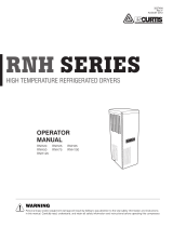
Compressor
Oil Removal
Filter
Aftercooler
Automatic Drain
Dryer
Separator
Receiver
TYPICAL COMPRESSED AIR SYSTEM
INSTALLATION
Ambient Air Temperature
Locatethedryerindoorswheretheambientairtemperature
willbebetween45°Fand110°F.Intermittentoperationat
ambient temperatures up to 113°F will not damage the dryer
but may result in a higher dew point or dryer shutdown
duetohighrefrigerantdischargepressure(seeFieldService
Guide).
Donotoperateair-cooleddryersatambientairtemperatures
below40°F.Suchoperationmayresultinlowsuction
pressure,causingfreeze-up.
Location and Clearance
Mountthedryeronalevelbase.Ifthebasevibrates,bolt
theunitdownusingvibrationdampeners.Ifthedryeris
air-cooled,installitinaclean,well-ventilatedareatoreduce
foulingofthecondensercoilswithdirtanddust.Allowat
least24inchesclearanceonthesidesandthefrontofthe
dryerforcoolingairowandforserviceaccess.
System Arrangement
Liquidwaterintheinletairwilladverselyaffectthe
performanceofthedryer.Installthedryerdownstreamofan
aftercoolerorseparatorsothatthetemperatureofthedryer
inletairdoesnotexceed120°Fandtheinletairdoesnot
contain any liquid water.
Ifthecompressedairowisrelativelyconstantanddoesnot
exceedthedryerowrating,itisrecommendedthatthe
dryerbelocateddownstreamofthereceivertank.Ifthe
natureoftheapplicationissuchthattheairdemandregularly
exceedsthedryerowrating,itisrecommendedthatthe
dryerbelocatedupstreamofthereceiver.
Forsafetyandconvenience,installinletandoutletshutoff
valvesanddepressurizationvalves.Thesevalvesallowthe
dryertobeisolatedanddepressurizedforservicing.Bypass
pipingmaybeinstalledaroundthedryerforuninterrupted
airowwhenthedryerisserviced.Ifthecompressedair
operationcannottolerateundriedairforshortperiods,install
a second dryer in the bypass line.
Compressedairsystemscommonlyrequirelterstoremove
compressoroils,particulates,condensedliquidsandother
contaminants.Whenanoil-removallterisused,itshould
beinstalleddownstreamoftherefrigerateddryer.At
thislocation,thelifeofthereplaceablelterelementis
prolongedsincesomeoftheentrainedoilisremovedbythe
dryer and drained through the separator.
Piping and Connections
Pipingmustbefurnishedbytheuserunlessotherwise
specied.Connectionsandttingsmustberatedforthe
maximumoperatingpressuregivenonthedryerdataplate
andmustbeinaccordancewithapplicablecodes.Support
allpiping;donotallowtheweightofanypipingtostressthe
dryerorlterconnections.Inletandoutletshutoffvalvesand
avalvedbypassvalvearerecommended.Pipingshouldbeat
leastthesizeoftheinletandoutletconnectionstominimize
pressuredropintheairsystem.SeeEngineeringDatasection
fordryerinletandoutletconnections.
Removing Condensate
Condensatemustbedrainedfromthedryertopreventre-
entrainment. The dryers are equipped with automatic drain
valves and internal drain hoses up to the drain connections
on the dryer cabinets. The user must install a separate
dischargelineatthedrainconnectiontocarryoffcondensate
to an environmentally approved condensate collection/
disposalsystem.Pipingorcoppertubing1/2inchorlarger
isrecommendedforcondensatedischargelines.Installthe
drain lines so that condensate can be seen as it drains.
Electrical Connections
ThedryersareconstructedaccordingtoNEMAType1
electrical standards. Field wiring must comply with local and
nationalre,safetyandelectricalcodes.Installationmust
beinaccordancewiththeNationalElectricalCode.Conrm
that your line voltage is the same as the voltage listed on the
dryerdataplate.RefertoFigure1forelectricalschematics.
Operation of dryers with improper line
voltage constitutes abuse and could affect the dryer
warranty.

4
INSTRUMENTATION
ON/OFF Switch
ThedryerisequippedwithanON/OFFswitchonthefront
panel.Alightsignalswhenthedryerison.
Dew Point Indicator
(75 through 150 scfm models)
Alldryersareequippedwithadewpointindicatorwhich
indicatesdryerconditionsasfollows:
Itisnormalforthedewpointindicatortobeintheredzone
whenthedryerisrstturnedonandthenmovetothe
greenzonewhenthedryerreachesitsnormaloperating
temperature.Ifthisindicatorisintheredzoneduring
normaloperation,turnthedryerofftoavoidcompressor
damage.RefertotheFieldServiceGuideforadditional
information,orcallyourlocaldistributor.
Dryer System Monitor (DSM)
(200 through 5000 scfm models)
TheDryerSystemMonitor(DSM)hasLEDtypedewpoint
temperature indicators and electronic drain valve timing
controls.Whenthedryerisrunningnormally,thegreenLEDs
willilluminate.IftheredLEDisilluminated,thereisaneed
forthedryer'soperatingconditiontobechecked.
NOTE:Whenthedryeristurnedon,allLEDswillbe
illuminated.Allow15minutesfortheredandyellowLEDsto
beextinguished.
Theautomaticdrainvalvecontrolsallowtheperiodofdrain
openingtobesetfrom0.5secondsto9secondsanddrain
valveclosedtimetobesetfrom0.5minutesto9minutes.
Whenthe"PUHTOTEST"buttonispushed,thedrainvalve
opensandremainsopenfortheadjusted"open"time.
Automatic Drain Valve
Allmodelsareequippedwithanelectronicdrainvalvethat
automaticallydischargescondensatefromthedryer.Drain
valve operation is controlled by a drain valve timer. The drain
openingcanbesetfrom0.5secondsto9seconds.Thedrain
cyclecanbesetfrom0.5minutesto9minutes.
Models75through150havethetimermounteddirectlyon
thedrainvalve.Formodels200through500,drainvalve
adjustmentsaremadeontheDryerSystemMonitor(DSM).
Electronic Drain Valve Adjustment
Tominimizeairlosses,thedrainvalvecontroltimeshould
beadjustedtoopenthedrainportjustlongenoughto
dischargeaccumulatedcondensate.Setthedrainvalve
operatingtimesothatonlyairdischargesattheendofthe
open period. Recommended initial settings are a 1 to 2
seconddrainopeningand30secondsdrainclosedtime.If
liquidstilldischargesastheportisclosing,setthetimerfora
shorter cycle or a longer opening.
timershouldbeadjustedtoopenthedrainportjustlong
enoughtodischargeaccumulatedcondensate.Setthetimer
sothatonlyairdischargesattheendoftheopenperiod.
Dew Point Indicator
(Models RNP75, RNP100, RNP125 and RNP150)
3 4
2
1
5
Drain Timer
(Models RNP75, RNP100, RNP125 and RNP150)
1. Adjustmentknobforthedrainvalveopentime.The
values on the dial correspond to the time in seconds
that the valve is open in each drain cycle.
2. Adjustmentknobforthedrainvalveclosedtime.The
values on the dial correspond to the time in minutes
that the valve is closed in each drain cycle.
3. LEDtoindicatewhenthedrainvalveisopen.
4. Draintestbutton.Whenthebuttonispressed,the
drainvalveopensforthetimecorrespondingtothe
setting on item 1.
5.LEDtoindicatewhenthedrainvalveisclosed.

5
2
1
10 9 8
7
6
543
Dryer System Monitor
(Models RNP200, RNP250, RNP300, RNP400 and RNP500)
1. On/OffSwitch:Pressthetopoftheswitch(I)toturn
thedryeron.Pressthebottomoftheswitch(O)to
turnthedryeroff.Whenthedryerison,theswitchis
illuminated.
2. ThisisagraphicsymbolfortheAirDryercompressor.
Itsimplyindicatesthattheswitchisusedtoturnthe
compressor(dryer)onandoff.
3. Partofthegraphicforthedewpointtemperature
scale.Thesnowflakeindicatesthelow(cold)endof
the scale.
4. Mainportionofthegraphicforthedewpoint
temperaturescale.Greenindicateslow,orange
indicatesmedium,redindicateshigh.
5. Partofthegraphicforthedewpointtemperature
scale. The thermometer indicates the high (hot) end
ofthescale.
6. Six(6)LEDsthatindicatedewpointtemperature
accordingtothegraphicscaleabovetheLEDs.The
colorofeachLEDmatchesthecoloredbars
7. Adjustmentknobforthedrainvalveopentime.The
values on the dial correspond to the time in seconds
that the valve is open in each drain cycle.
8. Adjustmentknobforthedrainvalveclosedtime.The
values on the dial correspond to the time in minutes
that the valve is closed in each drain cycle.
9. LEDtoindicatewhenthedrainvalveisopen.
10. Draintestbutton.Whenthebuttonispressed,the
drainvalveopensforthetimecorrespondingtothe
settingonitem7.

6
START-UP/OPERATION
Follow the procedure below to start your dryer. Failure
tofollowtheprescribedstart-upprocedurewillinvalidate
thewarranty.Ifproblemsariseduringstart-up,callyour
distributor.
RefertoSerialNumberTagfordryeroperating
capacity.Donotexceedrecommendedcapacity.
Drainconnectionsmustbemadebeforethedryercanbe
operated.Thedryersarefullyautomaticandrequireno
auxiliarycontrols.
1. TurnthedryerON/OFFswitchtoOFF.
2. Checkthatthemainelectricalsupplyvoltagematches
thevoltagespeciedonthedryerdataplate.
3. Checkproperconnectionandsupportofcompressedair
linestothedryer;checkbypassvalvesystem,ifinstalled.
4. SLOWLYpressurizethedryer.Theoutletvalvesofthe
dryershouldbeclosedtopreventowthroughthe
dryer.
5. Turn on the main electrical power to the dryer.
6. Ensureadequateventilationforair-cooleddryers.
To start dryer:
1. Turn the power switch to ON.Therefrigerantcompressor
will turn on.
2. Allowthedryertorun15minutes.Conrmthatthe
temperatureindicatorsareinthegreenzone.
3. SLOWLYopenthedryeroutletvalvespermittingow
through the dryer.
4. Conrmthatcondensateisdischargingfromthedrain
valvebypressingthe"TEST"button.
5. Checkdrainvalvetiming.SeeAUTOMATICDRAINVALVE
sectionfordrainvalveadjustmentprocedure.
6. Conrmthattheinletairtemperature,pressureand
airowtothedryermeetthespeciedrequirements(see
EngineeringDatasection).
7. Conrmthatthecondensatelinesfromthedrainvalve
dischargeintoacollectiontankoranenvironmentally-
approved disposal system.
Thedryerisdesignedtoruncontinuously.Letthedryerrun
evenwhenthedemandforcompressedairisinterrupted;
thedryerwillnotfreezeup.
SHUTDOWN
Whenthedryermustbeshutdownformaintenanceorother
reasons,usethefollowingprocedure.
Ifelectricalrepairsmustbemade:
1. Turnoffthepowerswitch.
2. Disconnectthemainpowersupply.
3. Lockoutandtagthepowersupplyinaccordancewith
OSHArequirements.
Ifmechanicalrepairsaretobemadeorserviceisperformed,
venttheinternalpressureofthedryertoatmospheric
pressure.Restartthedryeraccordingtothestart-up
instructions.
Disconnectpowersupplyanddepressurize
dryerbeforeservicing.Dismantlingorworkingonany
componentofthecompressedairsystemunderpressure
maycauseequipmentfailureandseriouspersonalinjury.
MAINTENANCE
Thedryersrequirelittlemaintenanceforsatisfactory
operation.Gooddryerperformancecanbeexpectedifthe
followingroutinemaintenancestepsaretaken.
Dismantlingorworkingonanycomponent
ofthecompressedairsystemunderpressuremaycause
equipmentfailureandseriouspersonalinjury.Before
dismantlinganypartofthedryerorcompressedairsystem,
completely vent the internal pressure to the atmosphere.
General
Forcontinuedgoodperformanceofyourrefrigerateddryer,
allrefrigerationsystemmaintenanceshouldbeperformedby
acompetentrefrigerationmechanic.
NOTE:Beforecorrectivemaintenanceisdoneduringthe
warrantyperiod,callyourlocaldistributorandproceed
accordingtoinstructions.Refertothewarrantyforlimitsof
your coverage.
Daily Maintenance
Checktheoperationoftheautomaticdrainvalveatleast
oncedaily.SeetheFieldServiceGuideforremediestodrain
valvemalfunctions.SeetheAUTOMATICDRAINVALVE section
fordrainvalveadjustment.

7
Weekly Maintenance
Inspecttheambientairlterweeklyandcleanitifnecessary.
Dirtyairlterscauselossofefciencyandmayresultin
damage to the product.
AirFilter—Cleanaccumulateddustanddirtfromairlter
weeklyasrequired.
1. Openambientltersidedoor.
2. Removeairlterbyslidingupwards.
3. Washwithsoapandwaterandallowtodrybefore
reinstalling.
NOTE:Donotusesolventstocleanlter.
4. Reinstallairlterandrightsidedoor.
5. Ifthelterisdamaged,replaceitwithanewlter.
Contact your distributor.
Donotoperatethedryerwithouttheambient
airlter.Permanentcondenserdamagemayresult.
Monthly Maintenance
Forair-cooledcondensers,itisrecommendedtoinspect
thecondensercoilsmonthly.Ifnecessary,removedirtor
otherparticleswithcompressedairfromanOSHA-approved
airnozzlethatlimitsitsdischargepressureto30psig
(2.1kgf/cm²).
Electronic Drain Valve Disassembly and Servicing
Donotdisassembledrainvalvetimerorattempt
torepairelectricalparts.Replacetimerifdefective.
Thedrainvalvedischargecondensatethroughafull-port
drain opening. The valve body may need to be cleaned under
conditionsofgrossparticulatecontamination.
Todisassemblethedrainvalvebodyforcleaningandother
maintenance:
1. Turnpowerswitchoff.
2. Disconnectmainpowersupplytodryer.
3. Depressurizeunit.
4. LockoutandtagpowersupplyinaccordancewithOSHA
requirements.
Ifpowersupplyisnotconnectedandunitis
notdepressurizedbeforedisassembly,seriouspersonalinjury
and valve damage may result.
5. Removes hoses that connect the drain valve to the drain
valve strainer.
6. Removescrewandwasherfromfrontofthedrainvalve.
7. Removethepowersupplyconnectorandgasket(with
thetimerassemblyifattached)fromthesolenoidcoil
housing.Donotdamageorlosethegasket.
8. Removecoilxingnutandspringwasherfromtopof
solenoid coil housing.
9. Liftsolenoidcoilhousingoffsolenoidcoreinvalvebody.
10. Unscrewsolenoidcorefromvalvebody.
Oncethedrainvalveisdisassembled,thefollowing
maintenancecanbeperformed.
1. Inspectinternalpartsofvalvebody;cleanorreplaceas
required.
NOTE:Replacesolenoidvalveifcomponentdamageis
observed.
2. Removedebrisfromvalvebody.
3. Wipesolenoidcorecomponentswithacleanclothor
blowoutdebriswithcompressedairfromanOSHA-
approvedairnozzlethatlimitsitsdischargepressureto
30 psig.
4. Checkthattheplungerassemblyiscleanandmoves
freelyinhousing.
5. Iftimerisattachedtovalvebody,checkelectrical
continuity across timer assembly.
Toreassemblethedrainvalve,reversethesequence
oftheprecedingsteps.Afterthedrainvalveis
reassembled,connectthemainpowersupplytothe
dryer.Whenthedryerisreturnedtoservice,check
thedrainvalveforairorcondensateleaks;tighten
connectionsasrequiredtocorrectleaks.Checkthedrain
cycle;adjustthetimeraccordingtotheprocedureinthe
drainvalveadjustmentsection.
Returns to Manufacturer
Ifthedryeroracomponentofthedryermustbereturnedto
themanufacturer,rstcallyourlocaldistributorforareturn
authorizationnumberandshippingaddress.Yourdistributor
willinformyouwhetherthedryeroronlyacomponentmust
bereturned.Markthepackagewiththereturnauthorization
numberandshipfreightprepaidasdirectedbyyourlocal
distributor.

8
FIELD SERVICE GUIDE
Problemsmostfrequentlyencounteredwithrefrigerated
dryersarewaterdownstreamofthedryerandexcessive
pressuredrop.Mostcausescanbeidentiedandremedied
byfollowingthisguide.
Closedrefrigerationsystemsarepotentially
dangerous.Workontherefrigerationsystemmustbedone
onlybyacompetentlicensedrefrigerationmechanic.Donot
releaseuorocarbonrefrigerantstotheatmosphere.Donot
dischargeliquidrefrigerantsintooordrains.Refrigerant
vaporsmayaccumulateinlowplaces.Inhalationofhigh
concentrationsmaybefatal.Allrefrigerantsmustbe
recoveredperEPArequirements.
Donotsmokewhenarefrigerationleakissuspected.Burning
materialsmaydecomposerefrigerants,formingatoxicgasor
acidsthatmaycauseseriousinjuryandpropertydamage.
Beforedismantlinganypartofthedryerorcompressed
airsystem,completelyventtheinternalpressuretothe
atmosphere.
PROBLEM SYMPTOM POSSIBLE CAUSE REMEDY
Water Downstream of
Dryer
Refrigerantcompressornot
running.
Lossofpowertodryer Checkpowersupply,fusesand/orbreakers.Check
forlooseconnections.
Dryerturnedoff. CheckOn/Offswitchposition.
Dryeroverloaded. Conrmthatinletow,inlettemperatureandinlet
pressurearewithinacceptablerangeofdryer.
Condenser clogged with debris. Check/cleanambientairlterandcondenser.
Fan motor inoperative Checkfanmotoroperation.Replaceifnecessary.
Ambienttemperaturetoohigh. Verifyambienttemperaturethroughoutday.
Highpressureswitchactivated
(models 200 to 500 only)
Pressmanualresetbuttontoswitchtoresetbutton.
Compressor overheated. Turndryeroff.Contactlocaldistributor.
Compressordefective. Turndryeroff.Contactlocaldistributor.
Nocondensatedischargingfrom
dryer.
Drainstrainerclogged. Clean drain strainer.
Drainvalveinoperative. Check/rebuilddrainvalve.
DraintimerorDSMinoperative. ConrmthereispowertothetimerorDSM.
ReplacetimerorDSM,ifnecessary.
Drainsolenoidinoperative. Conrmthereispowertothecoil.Replacecoil,if
necessary.
Condensatedischargingfromdryer. Incorrectdraintimersetting. Adjustdraintimer-increaseopentimeand/or
decrease closed time.
Liquidwaterenteringdryer. Aftercoolerdrainvalvemalfunction. Check,repairaftercoolerdrainvalve.
Excessive Pressure
Drop Across Dryer
Frozencondensateinevaporator. Incorrecthotgasbypassvalve
setting.
Contact local distributor.
Inletairpressurelow. Upstreamrestrictioninairsystem. Checkallupstreamairsystemcomponents(valves,
regulators,etc.)
Dryerundersized. Excessivecompressedairow. Resizedryer.
Dew Point Indicator
Out of Green Zone
Dryeroverloaded. Conrmthatinletow,inlettemperatureandinlet
pressurearewithinacceptablerangeofdryer.
Condenser clogged with debris. Check/cleanambientairlterandcondenser.
Loosesensorconnection. ConrmgaugeorDSMsensoristightlyconnected
to dryer tubing.
Defectivegauge,DSMorDSM
sensor.
Replacegauge,DSMorDSMsensor.

9
ENGINEERING DATA
MODEL 75 100 125 150 200 250 300 400 500
SPECIFICATIONS
Rated Capacity
a
-(scfm) 75 100 125 150 200 250 300 400 500
Inlet/OutletConnections-(inches) 3/4 1 1 1 1-1/2 1-1/2 1-1/2 2 2
Dimensions
Height-(inches) 20.1 20.6 20.6 20.6 30.0 30.0 29.9 29.9 31.5
Length-(inches) 19.7 28.3 28.3 28.3 35.4 35.4 37.4 37.4 41.3
Width-(inches) 18.9 13 13 13 16.1 16.1 19.3 19.3 23.2
PowerSupply-(V/Ph/Hz) 115/1/60 115/1/60 115/1/60 115/1/60 460/3/60 460/3/60 460/3/60 460/3/60 460/3/60
RefrigerantCompressorCapacity
c
-
(BTU/hr)
3,414 3,953 3,953 5,406 8,787 13,969 13,969 17,574 22,151
InputPower-(kW) 0.72 0.74 0.76 1.11 1.42 1.98 2.05 2.50 3.06
RefrigerantType
b
R-134a R-134a R-134a R-134a R-134a R-134a R-134a R-134a R-134a
a
Rating conditionsare100°Finlettemperature,100psiginletpressure,100%inletrelativehumidity,100°Fambienttemperature@60Hz.PerCAGIADF-100.
b
Refertodryerdataplateforrefrigerantcharge.
c
Compressorcapacity@35°Fevaporatingtemperature,130°Fcondensingtemperature.
MINIMUM - MAXIMUM OPERATING CONDITIONS ALL MODELS
Min.-Max.InletAirPressure(compressedairatinlettodryer) 10-232psig
Min.-Max.InletAirTemperature(compressedairatinlettodryer) 40°F-120°F
Min.-Max.AmbientTemperature 40°F-110°F
NOTE:Continuousoperationintheabovemaximumandminimumoperationconditionsisnotallowable.
SUCTION PRESSURE REFRIGERANT PRESSURE SWITCH SETTINGS
Refrigerant Without Airflow
Models75to500
R-134a 31 psig
Fan Cycle Control
FanPressureSwitchSetting
R-134a
Cut-In Cut-Out
199psig 142 psig
Models200to500
RefrigerantCompressorControl
HighPressureSwitchSetting
SensorLocation
R-134a
Cut-Out Cut-In
CompressorDischarge
298psig
Manual Reset
201 psig

10
ELECTRICAL SCHEMATICS
Figure 1b
100 to 125 scfm models
115V / 1PH / 60Hz
ON/OFF SWITCH
WITH RUNNING LAMP
R
2
5
CS CR
1
3
6
PTC STARTER
F. P. S.
FAN
MOTOR
T
ELECTRONIC AUTO DRAIN VALVE
OVERLOAD
PROTECTOR
COMP.
1PH
S
M
C
Figure 1a
75 scfm models
115V/1PH/60Hz
5
6
ON/OFF SWITCH
WITH RUNNING LAMP
R
2
F. P. S
MS
C
COMP.
1PH
OVERLOAD
PROTECTOR
PTC STARTER
FAN
MOTOR
ELECTRONIC
AUTO DRAIN
VALVE
T

11
ELECTRICAL SCHEMATICS
Figure 1d
200 to 500 scfm models
Figure 1c
150 scfm models
115V/1PH/60Hz
R
ON/OFF SWITCH
WITH RUNNING LAMP
ELECTRONIC
AUTO DRAIN
VALVE
Starting
Capacitor
S
R
COMP.
1~
C
P.R-b
Potential
Relay
FAN
MOTOR
Overload
protector
(OLP)
P. R
T
F. P. S
H.P. S
* FUSE FOR ELECTRO
AUTO DRAIN VALVE
SENSORELECTRO AUTO
DRAIN VALVE
* FUSE
U1
RL1
DSM
SOL
21
21
24
3
F1(2A)
ON/OFF SWITCH
WITH RUNNING LAMP
SRT
0V
R
440V
T
380V
TR 150VA
115V
0V
MC1
11
460V/3Ø/60Hz
F. P. S
31
21
24 24
1
2
3
4
5
6
7
o
o
o
o
o
o
o
R
MC1
REF. COMP.
With internal T.P
M
FAN MOTOR
With internal T.P

12
Figure 2a
75 to 150 scfm models
AIR AND REFRIGERANT FLOW SCHEMATICS
DRAIN VALVE
STRAINER
FAN PRESSURE SWITCH
FILTER/DRYER
REFRIGERANT
COMPRESSOR
CONDENSER
FAN BLADES
& FAN MOTOR
AIR FLOW
CHILLER
(REF TO AIR HEAT EXCHANGER)
REHEATER
(AIR TO AIR HEAT EXCHANGER)
COMPRESSED AIR INLET
COMPRESSED AIR OUTLET
S
MOISTURE SEPARATOR INTEGRATED BRAZED PLATE HEAT EXCHANGER
ELECTRONIC AUTO
DRAIN VALVE WITH TIMER
CAPILLARY TUBE
HOT GAS
BY-PASS VALVE
F. P. S

13
Figure 2b
200 to 500 scfm models
AIR AND REFRIGERANT FLOW SCHEMATICS
DRAIN VALVE
STRAINER
FILTER/DRYER
REFRIGERANT
COMPRESSOR
CONDENSER
FAN BLADES
& FAN MOTOR
AIR FLOW
CHILLER
(REF TO AIR HEAT EXCHANGER)
REHEATER
(AIR TO AIR HEAT EXCHANGER)
COMPRESSED AIR INLET
COMPRESSED AIR OUTLET
S
MOISTURE SEPARATOR INTEGRATED BRAZED PLATE HEAT EXCHANGER
ELECTRONIC AUTO
DRAIN VALVE
HIGH PRESSURE SWITCH
HOT GAS BY-PASS VALVE
CAPILLARY TUBE
FAN PRESSURE SWITCH
H.P. SF. P. S

14
REPLACEMENT PARTS
Item Description 75 scfm 100 scfm 125 scfm 150 scfm
1 RefrigerantCompressor 3149274 3161249 3161249 3161250
2 Condenser(air-cooled 1283269 3161253 3161253 3161254
3 Fan Blades 3041954 3041954 3041954 3041954
4 FanMotor 3161257 3161257 3161257 3161257
5 FilterDryer 3161259 1283273 1283273 1283273
6 SolenoidValveAssembly 3161263 3161263 3161263 3161263
7 SolenoidValveTimer 3161264 3161264 3161264 3161264
8 SolenoidValveStrainer 3161265 3161265 3161265 3161265
9 DINSocket 3161266 3161266 3161266 3161266
10 On/OffSwitchwithRunningLamp 3161244 3161244 3161244 3161244
11 DewPointIndicator 3041493 3041493 3041493 3041493
12 HotGasBypassValve 3161268 3161268 3161269 3161270
13 HeatExchanger 3161275 3161276 3161277 3161277
14 AmbientAirFilter — 3161260 3161260 3161260
15 FanPressureSwitch 3161274 3161274 3161274 3161274
16 MaintenanceKits RNPJMK3 RNPJMK3 RNPJMK3 RNPJMK3
Item Description 200 scfm 250 scfm 300 scfm 400 scfm 500 scfm
1 RefrigerantCompressor 3161251 3093041 3137014 3090708 3161242
2 Condenser(air-cooled) 3161255 3161255 3161256 3161256 3161245
3 Fan Blades 3041955 3041955 3041957 3041957 3041957
4 FanMotor 5000011 5000011 5000011 5000011 5000011
5 FilterDryer 1283273 1283273 1283369 1283369 1283369
6 SolenoidValveAssembly 3161248 3161248 3161248 3161248 3161248
7 SolenoidValveTimer — — — — —
8 SolenoidValveStrainer 3146976 3146976 3146976 3146976 3146976
9 DINSocket 3161267 3161267 3161267 3161267 3161267
10 On/OffSwitchwithRunningLamp 3161244 3161244 3161244 3161244 3161244
11 DryerSystemMonitor(DSM) 3161282 3161282 3161282 3161282 3161282
12 HotGasBypassValve 3161271 3161271 3161271 3161272 3161272
13 HeatExchanger 3161278 3161279 3161280 3161281 3161246
14 AmbientAirFilter 3161261 3161261 3161262 3161262 3161247
15 FanPressureSwitch 3161274 3161274 3161274 3161274 3161274
16 HighPressureSwitch 3161273 3161273 3161273 3161273 3161273
17 MaintenanceKits RNPJMK4 RNPJMK4 RNPJMK5 RNPJMK5 RNPJMK6

15

AUTHORIZATION FROM THE SERVICE DEPARTMENT IS NECESSARY BEFORE MATERIAL IS
RETURNED TO THE FACTORY OR IN-WARRANTY REPAIRS ARE MADE.
WARRANTY
Themanufacturerwarrantstheproductmanufacturedbyit,whenproperlyinstalled,operated,applied,andmaintainedinaccordancewithproce-
duresandrecommendationsoutlinedinmanufacturer’sinstructionmanuals,tobefreefromdefectsinmaterialorworkmanshipforaperiodas
speciedbelow,providedsuchdefectisdiscoveredandbroughttothemanufacturer’sattentionwithintheaforesaidwarrantyperiod.
Themanufacturerwillrepairorreplaceanyproductorpartdeterminedtobedefectivebythemanufacturerwithinthewarrantyperiod,provided
suchdefectoccurredinnormalserviceandnotasaresultofmisuse,abuse,neglectoraccident.Normalmaintenanceitemsrequiringroutinereplace-
mentarenotwarranted.Thewarrantycoverspartsandlaborforthewarrantyperiodunlessotherwisespecied.Repairorreplacementshallbemade
atthefactoryortheinstallationsite,atthesoleoptionofthemanufacturer.Anyserviceperformedontheproductbyanyoneotherthanthemanu-
facturermustrstbeauthorizedbythemanufacturer.
Unauthorizedservicevoidsthewarrantyandanyresultingchargeorsubsequentclaimwillnotbepaid.Productsrepairedorreplacedunderwarranty
shallbewarrantedfortheunexpiredportionofthewarrantyapplyingtotheoriginalproduct.
Theforegoingistheexclusiveremedyofanybuyerofthemanufacturer’sproduct.Themaximumdamagesliabilityofthemanufactureristheoriginal
purchasepriceoftheproductorpart.
THEFOREGOINGWARRANTYISEXCLUSIVEANDINLIEUOFALLOTHERWARRANTIES,WHETHERWRITTEN,ORAL,ORSTATUTORY,ANDISEXPRESSLYINLIEU
OFTHEIMPLIEDWARRANTYOFMERCHANTABILITYANDTHEIMPLIEDWARRANTYOFFITNESSFORAPARTICULARPURPOSE.THEMANUFACTURERSHALL
NOTBELIABLEFORLOSSORDAMAGEBYREASONOFSTRICTLIABILITYINTORTORITSNEGLIGENCEINWHATEVERMANNERINCLUDINGDESIGN,MANUFAC-
TUREORINSPECTIONOFTHEEQUIPMENTORITSFAILURETODISCOVER,REPORT,REPAIR,ORMODIFYLATENTDEFECTSINHERENTTHEREIN.
THEMANUFACTURER,HISREPRESENTATIVEORDISTRIBUTORSHALLNOTBELIABLEFORLOSSOFUSEOFTHEPRODUCTOROTHERINCIDENTALORCONSE-
QUENTIALCOSTS,EXPENSES,ORDAMAGESINCURREDBYTHEBUYER,WHETHERARISINGFROMBREACHOFWARRANTY,NEGLIGENCEORSTRICTLIABILITY
INTORT.
Themanufacturerdoesnotwarrantanyproduct,part,material,component,oraccessorymanufacturedbyothersandsoldorsuppliedinconnection
withthesaleofmanufacturer’sproducts.
Warranty Period
Partsandlaborfortwo(2)yearsfromthedateofshipmentfromthefactory;heatexchangersarecovered(partsonly)foranadditionalthree(3)
years(totalofve[5]).Onunitsthatmanufacturerrequestsbereturnedtothefactory,aonetimeremoval/reinstallationlaborallowanceasnotedin
theServiceWarrantyPoliciesandProceduresHandbookwillapply.Freighttothefactoryfromtheinstallationsiteandtotheinstallationsitefromthe
factorywillbepaidbythemanufacturer;meansoftransportationtobespeciedbymanufacturer.
SERVICE DEPARTMENT: (724) 746-1100
Curtis-Toledo, Inc.
1905 Kienlen Avenue, St. Louis Missouri 63133
WWW.FSCURTIS.COM
/