Page is loading ...

Thank you for purchasing a Panasonic Single Monitor Station.
Please read this Installation and Operation Guide before using the unit and save for future
reference.
Single Monitor Station
Installation and Operation Guide
Model No.
VL-GM201A
GM201A.book Page 1 Monday, April 4, 2005 5:10 PM

2
Table of Contents
Important Information
Important safety instructions . . . . . . . . . . . . . . . . . . . . . . . . . . . . . . . . . . . . . . . . . . . . . . . . 3
Additional safety information . . . . . . . . . . . . . . . . . . . . . . . . . . . . . . . . . . . . . . . . . . . . . . . . 4
For best performance. . . . . . . . . . . . . . . . . . . . . . . . . . . . . . . . . . . . . . . . . . . . . . . . . . . . . . 5
Introduction and Installation
Included items . . . . . . . . . . . . . . . . . . . . . . . . . . . . . . . . . . . . . . . . . . . . . . . . . . . . . . . . . . . 6
Optional item information . . . . . . . . . . . . . . . . . . . . . . . . . . . . . . . . . . . . . . . . . . . . . . . . . . . 7
Compatible PBXs . . . . . . . . . . . . . . . . . . . . . . . . . . . . . . . . . . . . . . . . . . . . . . . . . . . . . . . . . 7
Location of controls . . . . . . . . . . . . . . . . . . . . . . . . . . . . . . . . . . . . . . . . . . . . . . . . . . . . . . . 8
Before installation. . . . . . . . . . . . . . . . . . . . . . . . . . . . . . . . . . . . . . . . . . . . . . . . . . . . . . . . 10
Installing the monitor station . . . . . . . . . . . . . . . . . . . . . . . . . . . . . . . . . . . . . . . . . . . . . . . 12
Using the desktop stand (Optional) . . . . . . . . . . . . . . . . . . . . . . . . . . . . . . . . . . . . . . . . . . 19
Using the Unit
Turning {PBX MODE} switch ON/OFF . . . . . . . . . . . . . . . . . . . . . . . . . . . . . . . . . . . . . . . 20
Connecting to a PBX . . . . . . . . . . . . . . . . . . . . . . . . . . . . . . . . . . . . . . . . . . . . . . . . . . . . . 22
Answering a door call using the monitor station. . . . . . . . . . . . . . . . . . . . . . . . . . . . . . . . . 23
Monitoring the outside . . . . . . . . . . . . . . . . . . . . . . . . . . . . . . . . . . . . . . . . . . . . . . . . . . . . 26
Opening a door (door opener) . . . . . . . . . . . . . . . . . . . . . . . . . . . . . . . . . . . . . . . . . . . . . . 27
Help
Troubleshooting . . . . . . . . . . . . . . . . . . . . . . . . . . . . . . . . . . . . . . . . . . . . . . . . . . . . . . . . . 28
Cleaning . . . . . . . . . . . . . . . . . . . . . . . . . . . . . . . . . . . . . . . . . . . . . . . . . . . . . . . . . . . . . . . 29
General Information
Technical data about this product . . . . . . . . . . . . . . . . . . . . . . . . . . . . . . . . . . . . . . . . . . . 30
FCC and Other Information . . . . . . . . . . . . . . . . . . . . . . . . . . . . . . . . . . . . . . . . . . . . . . . . 31
GM201A.book Page 2 Monday, April 4, 2005 5:10 PM

3
Important Information
Important safety instructions
1) Read these instructions.
All the safety and operating instructions should be read before the appliance is operated.
2) Keep these instructions.
The safety and operating instructions should be retained for future reference.
3) Heed all warnings.
All warnings on the appliance and in the operating instructions should be adhered to.
4) Follow all instructions.
All operating and use instructions should be followed.
5) Do not use this apparatus near water.
For example, near a bathtub, wash bowl, kitchen sink, or laundry tub, in a wet basement,
or near a swimming pool, and the like.
6) Clean only with dry cloth.
Do not use liquid cleaners or aerosol cleaners. Use a dry cloth for cleaning.
7) Do not block any ventilation openings.
Install in accordance with the manufacturer’s instructions.
Slots and Openings in the cabinet are provided for ventilation and to ensure reliable
operation of the product and to protect it from overheating. The openings should never be
blocked by placing the product on a bed, sofa, rug, or other similar surface.
8) Do not install near any heat sources such as radiators, heat registers, stoves, or other
apparatus (including amplifiers) that produce heat.
This product should not be placed in a built-in installation such as a bookcase or rack
unless proper ventilation is provided or the manufacturer’s instructions have been
adhered to.
9) Do not defeat the safety purpose of the polarized or grounding-type plug.
A polarized plug has two blades with one wider than the other. A grounding type plug has
two blades and a third grounding prong. The wide blade or the third prong are provided for
your safety. If the provided plug does not fit into your outlet, consult an electrician for
replacement of the obsolete outlet.
10) Protect the power cord from being walked on or pinched particularly at plugs, convenience
receptacles, and the point where they exit from the apparatus.
11) Only use attachments / accessories specified by the manufacturer.
The lightning flash with arrow
head within a triangle is
intended to tell the user that
parts inside the product are a
risk of electric shock to persons.
The exclamation point within a
triangle is intended to tell the
user that important operating
and servicing instructions are in
the papers with the appliance.
CAUTION
RISK OF ELECTRIC SHOCK
DO NOT OPEN
GM201A.book Page 3 Monday, April 4, 2005 5:10 PM

4
Important Information
12) Unplug this apparatus during lightning storms or when unused for long periods of time.
This will prevent damage to the product due to lightning and power-line surges.
13) Refer all servicing to qualified service personnel. Servicing is required when the
apparatus has been damaged in any way, such as power- supply cord or plug is damaged,
liquid has been spilled or objects have fallen into the apparatus, the apparatus has been
exposed to rain or moisture, does not operate normally, or has been dropped.
SAVE THESE INSTRUCTIONS
Additional safety information
1. Use only the power source marked on the unit. If you are not sure of the type of power
supplied to your home, consult your dealer or local power company.
2. Use only the specified AC adaptor.
3. Do not tamper with the plug.
4. Make sure the plug is securely inserted.
5. Do not touch the plug with wet hands.
6. Do not place objects on the power cord. Install the unit where no one can step or trip on
the cord.
7. To reduce the risk of electric shock, do not disassemble this unit. Take the unit to an
authorized service center when service is required. Opening or removing covers may
expose you to dangerous voltages or other risks. Incorrect reassembly can cause electric
shock when the unit is subsequently used.
8. Unplug this unit from power outlets and refer servicing to an authorized service center
when the following conditions occur:
A. If smoke rises, or an unaccustomed noise or smell is discharged from the unit.
B. If metal objects have been dropped inside the monitor station.
9. Do not put your ear(s) near the speaker, as loud sounds emitted from the speaker may
cause hearing impairment.
10. Only a qualified technician is allowed to connect a power cable to the unit.
Contact an authorized service center.
11. Do not make any wiring connections when the power supply is turned on.
12. Never install wiring during a lightning storm.
13. Do not connect a power cable other than the specified voltage.
14. Do not connect the power cable to any terminal other than the one specified.
15. When existing chime wires are used, it is possible that they contain AC voltage. Electric
shock or unit damage could result. Contact an authorized service center.
16. Never touch the inside of the monitor station. High voltage is present.
17. Make certain when mounting the unit to any wall surface that the method used will hold the
weight of the unit properly.
18. If the wiring is outdoors, use a protection tube or a surge protector.
19. If the wiring is underground, do not make any connections underground.
20. WARNING
– To Reduce The Risk Of Fire Or Electric Shock, Do Not Expose This
Apparatus To Rain Or Moisture.
GM201A.book Page 4 Monday, April 4, 2005 5:10 PM

5
Important Information
21. WARNING – Unplug this unit from power outlets if it emits smoke, an abnormal smell or
makes unusual noise. These conditions can cause fire or electric shock. Confirm that
smoke has stopped and contact an authorized service center.
For best performance
L If a power failure occurs, the unit will not function.
L Do not place any objects within 20 cm (8 inches) of the monitor station. This may cause
communication errors or malfunction.
Note:
L This product has a fluorescent lamp that contains a small amount of mercury. It also
contains lead in some components. Disposal of these materials may be regulated in your
community due to environmental considerations. For disposal or recycling information
please contact your local authorities, or the Electronics Industries Alliance:
<http://www.eiae.org.
>
20 cm
(8 inches)
20 cm
(8 inches)
20 cm
(8 inches)
20 cm
(8 inches)
GM201A.book Page 5 Monday, April 4, 2005 5:10 PM

6
Introduction and Installation
Included items
1234
567
No. Item Quantity Notes
1 Monitor station 1 ------
2 Mounting bracket 1 Attached to rear of the monitor station.
3 Wood screws 2 For the monitor station.
(4 mm x 16 mm,
3
/16" x
5
/8")
4 Power cable 1 ------
5 AC adaptor 1 Enclosed in the AC adaptor case.
6 Wood screws 2 For the AC adaptor case.
(4 mm x 16 mm,
3
/16" x
5
/8")
7 Power cord 1 ------
GM201A.book Page 6 Monday, April 4, 2005 5:10 PM

7
Introduction and Installation
Optional item information
Available optional items
– Door station
*1
(VL-GC001A, VL-GC002A)
– Desktop stand (VL-GT001A)
*1 The door station figures shown in this installation and operation guide are based on a VL-
GC001A.
Compatible PBXs
This unit is compatible with the following Panasonic PBXs
*1
:
– KX-TA308
– KX-TA624
– KX-TA824
– KX-TA1232
– KX-TAW848 (From Ver2.0)
– KX-TD308
– KX-TD816
– KX-TD1232
– KX-TDA50 (From Ver2.0)
– KX-TDA100 (From Ver2.01)
– KX-TDA200 (From Ver2.01)
*1 As of March, 2005. Consult your dealer for a current list of compatible PBXs.
GM201A.book Page 7 Monday, April 4, 2005 5:10 PM

8
Introduction and Installation
Location of controls
Front view Side view
Rear view
MONITOR
BRIGHT
DOOR
TALK
VOLUME
RINGER
VOLUME
RINGER
ANSWER
AUTO
PUSH
HOLD
HIGH
LOW
OFF
AN
S
W
E
R
AUTO
PUSH
HOLD
HIGH
LOW
OFF
B
I
D
E
F
J
G
A
H
C
OFF
PBX MODE
ON
K
GM201A.book Page 8 Monday, April 4, 2005 5:10 PM

9
Introduction and Installation
A Microphone
B Display
C MONITOR button
L Allows you to monitor the sound and camera image from the door station (page 26).
D BRIGHT button
L Allows you to adjust the display brightness. 5 levels are available.
E DOOR button
L Allows you to open the door (page 27).
F Speaker
G TALK button
L To answer a door call and/or speak to the visitor (page 23).
H Talk indicator
L Lights while you are talking.
I RINGER VOLUME switch
L To adjust the ringer volume. 3 levels (high/low/off) are available.
J ANSWER switch
L To change the answering mode (page 23).
K PBX MODE switch
L To connect the unit to a PBX, turn on this switch (page 20).
GM201A.book Page 9 Monday, April 4, 2005 5:10 PM

10
Introduction and Installation
Before installation
To avoid a malfunction or communication disturbance, do not install the monitor station in the
following locations:
– Places where vibration or any other kind of impact occurs.
– Places where echoing is frequent.
– Places where a high concentration of dust, hydrogen sulfide, phosphorus, ammonia, sulfur,
carbon, acid, or noxious fumes occur.
– Within 2 m (6'7") of a TV, microwave, personal computer, air conditioner or any other
electrical device.
Standard installation position of the monitor station
Place the monitor station in a location so that your eyes are the same height as the center of
the display.
Note:
L In areas surrounded by high electrical field, disturbance may occur in the monitor station’s
image or sound.
L Be sure to install the monitor station more than 5 m (16'5") away from the door station.
L Do not place any objects within 20 cm (8 inches) of the monitor station. This may cause
communication errors or malfunction.
L Do not install the monitor station inside a wall.
GM201A.book Page 10 Monday, April 4, 2005 5:10 PM

11
Introduction and Installation
Wiring schematic diagram
Note:
L This door opener wiring schematic diagram is only an example. Refer to the wiring
instructions provided with your door opener and PBX for details.
L Refer to the technical data on page 30 when connecting to a door opener.
Power cable/wire type and distance
L Power cable (between the monitor station and the AC adaptor):
Type: Ф1.2 Fire alarm cable 16 AWG
Distance: Maximum 30 m (about 98 feet)
L Wire (between the monitor station and the door station):
Type: General cable CAT-3 24 AWG
Distance: Maximum 100 m (about 328 feet)
Loop resistance: 18.4 Ω or lower
L Wire (between the monitor station and PBX):
Type: General cable CAT-3 24 AWG
Distance: Maximum 100 m (about 328 feet)
D1
D2
Door station
Monitor station
AC adaptor
Power cable
(Non polar)
(Non polar)
(Non polar)
D1
D2
P1
P2
S1
S2
PBX
(Example: KX-TDA50)
Door opener
Terminal box
(4-conductor wiring)
Power cord
GM201A.book Page 11 Monday, April 4, 2005 5:10 PM

12
Introduction and Installation
Installing the monitor station
Note:
L When connecting to a PBX, make sure the {PBX MODE} switch is set to {ON} before
installing the monitor station (page 20).
1 Install the mounting bracket to a wall using the wood screws (4 mm x 16 mm,
3
/16" x
5
/8").
L Remove the mounting bracket from the rear of the monitor station beforehand.
L Before drilling, see page 10 for installation location.
2 Attach the power cable to the terminal. See page 18 for details on how to attach the power
cable.
L If you want to use your own power cable, see page 11 for the type and distance.
Wall
Mounting bracket
83.5 mm
(3
5
/
16
")
Wood screws
Terminal (Non polar)
Power cable
GM201A.book Page 12 Monday, April 4, 2005 5:10 PM

13
Introduction and Installation
3 Attach the wires that connect to the door station to the terminal. See page 18 for details
on how to attach the wires.
L See page 11 for the wire type and distance.
L See the wiring schematic diagram on page 11.
L If you want to connect the wires and the power cable without them going through a hole
in the wall behind the mounting bracket, connect by passing the wires through the wire
guide, and the power cable through the power cable guide.
Button
Terminal
(Non polar)
Wire (Not included)
Stripped end of the wire
9 mm
(
3
/8")
Power cable guide
Wire guide
GM201A.book Page 13 Monday, April 4, 2005 5:10 PM

14
Introduction and Installation
4 Mount the monitor station to the mounting bracket.
Push the monitor station down until it is secure.
5 Take out the AC adaptor and the DC terminal from the case.
L Push the arrow mark on the front case, then release from the rear case.
L Take out the cardboard and wood screws. The wood screws are necessary when
attaching the AC adaptor and the DC terminal to a wall (page 16).
1
2
AC adaptor
DC terminal
Arrow mark
GM201A.book Page 14 Monday, April 4, 2005 5:10 PM

15
Introduction and Installation
6 Connect the power cable to the DC terminal, the power cord to the AC adaptor, then
connect the power cord to the AC outlet (100 V
– 240 V, 50 Hz / 60 Hz).
L Be sure to connect the power cable to the 2 holes on the left side of the DC terminal.
L For details on how to attach the power cable, see page 18.
7 Attach the DC cord to the clamp on the rear of the DC terminal.
L This will help to avoid the DC cord to disconnect from the DC terminal.
To AC outlet
DC terminal
Power cable
AC adaptor Power cord
1
2
3
DC cord
DC terminal
Clamp
GM201A.book Page 15 Monday, April 4, 2005 5:10 PM

16
Introduction and Installation
To attach the AC adaptor and the DC terminal to a wall
By placing the AC adaptor and the DC terminal in the case and mounting the case to the wall,
you can protect the AC adaptor and the DC terminal from tampering and exposure.
Note:
L Disconnect the DC cord from the clamp on the rear of the DC terminal beforehand. See
step 7 on page 15 for details.
L Take out the cardboard and wood screws from the AC case beforehand.
1 Attach the rear part of the case to a wall using the wood screws (4 mm x 16 mm,
3
/16'' x
5
/8'').
2 Pack the AC adaptor and DC terminal as shown.
1. Pack the AC adaptor in the rear case.
LBe sure to run the power cord through the power cord hole.
2. Pack the DC cord in the rear case.
LBe sure to bundle the DC cord so that it will not touch the bottom of the case.
3. Pack the DC terminal in the rear case.
LBe sure to run the wires through the wire hole, then under the wire rib.
Wall
Case
83.5 mm
(3
5
/
16
"
)
Wood screws
Wire rib
Wire hole
Power cord hole
Power cord
3 DC terminal
2 DC cord
1 AC adaptor
GM201A.book Page 16 Monday, April 4, 2005 5:10 PM

17
Introduction and Installation
3 Attach the front of the case.
Note:
L To open the case again, push the bottom of the front case, then release from the rear case.
1
2
GM201A.book Page 17 Monday, April 4, 2005 5:10 PM

18
Introduction and Installation
To attach the power cable
L While pressing on the button with a pointed object such as a screwdriver, insert the power
cable into the terminal connector.
L To disconnect the power cable, press on the button while pulling out.
L To attach an optional power cable, cut off about 12 mm (
1
/2") of the cable cover (1), then
push in firmly until the end of the cable is securely inserted into the power connection
terminal (2).
To attach the wires
L Strip off of the wire cover so that about 9 mm (
3
/8") of the wire is exposed.
L While pressing on the button with a pointed object such as a screwdriver, insert the wire into
the terminal connector.
L To disconnect a wire, press on the button while pulling out.
Monitor station DC terminal
12 Power cable cross section
Button
Terminal connector
Button
Terminal
connector
12 mm
(
1
/
2
")
Correct Incorrect
Button
Terminal connector
GM201A.book Page 18 Monday, April 4, 2005 5:10 PM

19
Introduction and Installation
Using the desktop stand (Optional)
You can place the monitor station on a desktop. See page 7 for optional item information.
Note:
L If you previously connected the power cable through the power cable guide (page 13),
remove the power cable from the power cable guide of the monitor station beforehand, then
attach to the desktop stand.
Desktop stand
Power cable
Mounting bracket
Wire
Wood screws
GM201A.book Page 19 Monday, April 4, 2005 5:10 PM

20
Using the Unit
Turning {PBX MODE} switch ON/OFF
When connecting to a PBX (page 22), turn {PBX MODE} switch on. If not, turn {PBX MODE}
switch off. The default setting is {ON}.
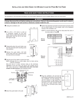
1 Remove the switch cover from the rear of the monitor station.
L Use a sharp, thin object such as a mechanical pencil.
2 Select {ON} (default) or {OFF}.
Switch cover
OFF
PBX MODE
ON
{PBX MODE} switch
GM201A.book Page 20 Monday, April 4, 2005 5:10 PM
/