Page is loading ...

In accordance with our policy of continuous product development and improvement,
this information is subject to change at any time without notice.
EI219350 Issued (JMT/KAK) 7 March, 2001
Manitowoc Beverage Equipment
2100 Future Drive Sellersburg, IN 47172-1868
Tel: 812.246.7000, 800.367.4233 Fax: 812.246.9922
www.manitowocbeverage.com
Foodservice Group
Multiplex Beverage Equipment Installation Instructions for
Electronic Temperature Control Retrofit Kit
for Model 150 Beermaster Glycol Chiller
P.N. 00219350
This kit is designed to replace the existing Ranco mechani-
cal temperature control in a Multiplex Model 150 Beermaster
Glycol Chiller. The Electronic Temperature Control (ETC) is
mounted on the outside of the Model 150 and provides a con-
stant readout of the sensor temperature.
Installing the electronic temperature
control retrofit kit
Tools Required
Screwdriver,
5
/32" Tip
Screwdriver,
1
/4" Tip
Wire Cutter/Stripper
Installation
1. Turn “OFF” all control switches on Multiplex Model 150
Beermaster Glycol Chiller.
2. Disconnect electrical power at branch circuit disconnect.
For cord-connected units, simply unplug the power cord.
3. Remove the cover panel from unit.
4. Remove the access panel from switch/control box.
5. Remove cover from temperature control mounted to back
of switch/control box.
6. Loosen two (2) terminal screws and disconnect both brown
wires.
7. Pull wires back through hole in rear of switch/control box.
8. Cut the terminal connectors off the brown wires and strip
the wire ends 5/16". Note that one (1) of the wires is
attached to one (1) of the control switches and the other
wire is routed through the opening in the bottom of the
switch/control box.
9. From inside of switch/control box, loosen and remove two
(2) screws that secure the temperature control. Remove
the temperature control from the unit.
10. Holding the ETC in front of the switch/control box with
the brown and blue wires protruding from the rear open-
ing, connect the blue wire to an open tab on the lower
bank of terminals on the terminal block.
11. Likewise, connect the brown wire to an open tab on the
upper bank of terminals on the terminal block.
12. Loosen the four (4) screws in the ETC cover and open the
ETC.
13. Route the two (2) newly stripped brown wires in the
switch/control box through the rear opening of the ETC.
14. Insert the stripped end of the wire connected to the con-
trol switch into opening “C” of the ETC lower terminal
block. Tighten the pressure screw to secure the wire.
15. Insert the other stripped wire end into the adjacent open-
ing, “NO”. Tighten the pressure screw to secure the wire.
16. Replace the cover on the ETC and temporarily secure by
partially starting two (2) diagonal screws (the cover will
be removed again later).
17. Route the sensor cord through an opening in the switch/
control box to the glycol tank
18. Using cable ties, secure the sensor to the bracket attached
to the evaporator.
19. Attach the ETC cover plate to the switch/control box us-
ing the original screws from the old access panel.

2
EI219350 Issued (JMT/KAK) 7 March, 2001
Equipment Installation Instructions
Caution: To Avoid Serious Injury
Important: Read the following warnings before beginning an installation. Failure to do so
may result in possible death or serious injury.
DO Adhere to all National and Local Plumbing and Electrical Safety Codes.
DO Turn “off” incoming electrical service switches when servicing, installing, or
repairing equipment.
DO Check that all flare fittings on the carbonation tank(s) are tight. This check
should be performed with a wrench to ensure a quality seal.
DO Inspect pressure on Regulators before starting up equipment.
DO Protect eyes when working around refrigerants.
DO Use caution when handling metal surface edges of all equipment.
DO Handle CO
2 cylinders and gauges with care. Secure cylinders properly against
abrasion.
DO Store CO2 cylinder(s) in well ventilated areas.
DO NOT Throw or drop a CO2 cylinder. Secure the cylinder(s) in an upright position
with a chain.
DO NOT Connect the CO2 cylinder(s) directly to the product container. Doing so will
result in an explosion causing possible death or injury. Best to connect the
CO2 cylinder(s) to a regulator(s).
DO NOT Store CO2 cylinders in temperature above 125°F (51.7°C) near furnaces,
radiator or sources of heat.
DO NOT Release CO2 gas from old cylinder.
DO NOT Touch Refrigeration lines inside units, some may exceed temperatures of
200°F (93.3°C).
Notice: Water pipe connections and fixtures directly connected to a potable water supply
shall be sized, installed and maintained in accordance with Federal, State, and Local codes.

3
EI219350 Issued (JMT/KAK) 7 March, 2001
Equipment Installation Instructions
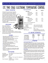
How to operate the electronic
temperature control
The LCD display provides a constant readout of the sensor
temperature and indicates if the output relay is energized.
The output relay controls operation of the refrigeration com-
pressor. When the S1 annunciator is constantly illuminated
during operation, the relay is energized and the compressor
should be running. The display is also used in conjunction with
the keypad to adjust the set-point temperature and differen-
tial.
Setup
The temperature set-point refers to the temperature at
which the normally open (NO) contacts of the output relay
will open. The differential refers to the number of degrees
between the set-point temperature and the temperature at
which the NO contacts close. The differential may be set for a
heating mode or cooling mode. For the cooling mode, the dif-
ferential is above the set-point. The relay will de-energize as
the temperature falls to the set-point. It will energize when
the temperature rises above the differential.
Programming Steps
1. Connect power to Model 150 Beermaster Glycol Chiller.
2. To program the ETC, press the SET (
) key once to access
the Fahrenheit/Celsius mode. The display will show the
current status, either F for degrees Fahrenheit or C for
degrees Celsius. Then press either the up arrow (
) or
down arrow (
) key to toggle to the F designation.
3. Press the SET ( ) key again to access the set-point. The
LCD will display the current set-point and the S1 annun-
ciator will be blinking “on” and “off” to indicate the
control is in the set-point mode. Then press the
up arrow (
) or down arrow ( ) key to set the set-point
at 28.
4. Press the SET (
) key again to access the differential.
The LCD will display the current differential and the DIF
1 annunciator will be blinking “on” and “off” to indicate
that the control is in the differential mode. Press the ap-
propriate up arrow (
) or down arrow ( ) to set the dif-
ferential to 2.
5. Press the SET (
) key again to access the cooling or heat-
ing mode. The LCD will display either C1 or H1. If H1 is
displayed, press either the up arrow (
) or down arrow ( )
to toggle to C1. Press the SET ( ) key once more and
programming is complete.
Note: The ETC will automatically end programming if no keys
are depressed for a period of thirty seconds. Any settings that
have been input to the control will be accepted at that point.
All control settings are retained in non-volatile memory if
power to the ETC is interrupted for any reason. Re-program-
ming is not necessary after power outages or disconnects un-
less different control settings are required.
Lockout Switch
The ETC is provided with a lockout switch to prevent tam-
pering by unauthorized personnel. When placed in the LOCK
position, the keypad is disabled and no changes to the set-
tings can be made.
1. To access the lockout switch, disconnect the power sup-
ply and open the control cover. The switch is located on
the inside of the cover about 2" (5.1 cm) above the bot-
tom.
2. To disable the keypad, slide the switch to the left LOCK
position.

4
EI219350 Issued (JMT/KAK) 7 March, 2001
Equipment Installation Instructions
Troubleshooting Error Messages
Display Error/Problem How to Correct
E1 Appears when either the up arrow ( ) or If the E1 message appears even when no keys are
down arrow (
) key is pressed when not in the being pressed, replace the control.
programming mode.
E2 Appears if the control settings are not properly Check all settings and correct if necessary.
stored in memory.
EP Appears when the probe is open, shorted or Check to see if the sensed temperature is out of
sensing a temperature that is out of range. range. If not, check for probe damage by
comparing to a known ambient temperature
between –30°F and 220°F. Replace the probe if
necessary.
EE Appears if the EEPROM data has been corrupted. This condition cannot be field repaired. Replace
the control.
CL Appears if the calibration mode has been entered. Disconnect power to the control for at least
5 seconds. Reconnect power. If the CL message
still appears, replace the control.
/