12
6. Troubleshooting
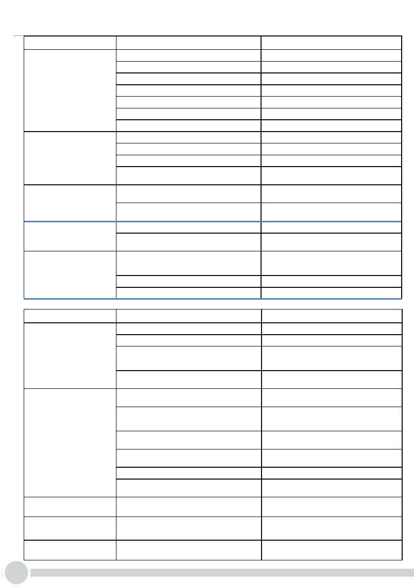
ISSUE PROBABLE CAUSE SOLUTION
The compressor will
not start
Power failure Check that there is voltage in the plug
Thermostat in the off position, or set to the minimum Check wirings and adjust the thermostat position
Faulty thermostat Check wirings replace the thermostat
The over-load protection of the compressor is faulty Wait for compressor cool down and replace it
The starting relay is faulty Check wiring replace the faulty component
The starting capacitor is faulty Check wiring replace the faulty component
The compressor is faulty Check wiring replace the faulty component
The water is cold but
the appliance is operating
excessively or
non-stop
Poor ventilation Place the appliance away from the wall
The condenser is dirty or covered Clean the condenser or free it from obstructions
The thermostat is on maximum cold position Adjust thermostat knob in the middle rotational range
Ambient temperature is higher than 32°C It is normal that the appliance works at a continuously high
room temperature
The compressor
works continuously,
but the water is not
cold
Gas leak from the cooling system Contact a specialized technician (refrigerator repairman) or
Marco Beverage Systems
The compressor is faulty Check wirings and voltage on compressor terminals and
replace the faulty component if needed.
Too much noise coming
from the equipment,
but it is working normally
The machine is not perfectly horizontal Level the appliance using the adjustable feet
Hoses and wirings are in contact with housing some parts inside
the equipment and generate noise and vibrations.
Check and reposition hoses and wirings, making sure they do
not touch any other parts.
Cold water comes out
slowly or not at all
Water inlet supply shutoff valve closed or faulty electrovalves
closed, water filter fouled/clogged.
Open water inlet supply line shutoff valve, check electrovalves
and anti-flooding device replace electrovalves ; replace filter
or cartridge.
Low pressure of the inlet net water Take steps to increase the net pressure (e.g. booster pump)
The thermostat is out of tolerance range or defective. Waiting for ice melting down. Replace Alublock thermostat.
ISSUE PROBABLE CAUSE SOLUTION
Too low CO
2
volume
CO
2
pressure too low Restore correct CO
2
pressure (typically about 4 bar / 60 psi)
CO
2
cylinder empty Replace CO
2
cylinder
Water temperature too high because cooling capacity is
exceeded by over drawing
See refrigeration/equipment specifications vs. volume
requirements and reduce amount of glasses taken per given
time of install higher volume unit.
Air trapped inside the carbonator Open carbonator vent check valve, pulling ring, until water
streams out.
CO
2
only flows out from faucet
Carbonator Electrode connection to wiring harness defective,
loose electrical connection and/or open circuit
Tighten connection, repair carbonator wiring harness
connection and check electrode connection at E.C.U.
The carbonation pump turns continuously No water is entering or the water filter is blocked or Hoses and
pipe fittings into the carbonator are obstructed.
Disassemble and clean it.
Check valve on carbonator water inlet failed open Verify correct behavior of the non-return (check valve)
assembled on the carbonator water inlet.
Inoperable water pump/ motor. Check for proper line voltage on component terminals.
Replace water pump/ motor if defective.
Electronic Control Unit (E.C.U.) defective. Replace E.C.U. assembly.
E.C.U. in timeout (> 240” continuous operation) Reset Timeout protection switching off equipment and waiting
60” before repower it.
Short cycling of water pump
motor
Carbonator Electrode connection to wiring harness defective or
reversed.
Repair carbonator wiring harness connection and check
electrode connection at E.C.U.
Continuous dripping
from the outlets
Few drops, mainly after soda dispensing is normal. If dripping is
continuous faucet or internal electrovalve could be dirty.
Disassemble the internal solenoid valve and clean it.
Still water comes out
carbonated
Internal check valve could be dirty. Disassemble check valve and clean it. Replace if needed.
SOLUTION
Check that there is voltage in the plug
Check wirings and adjust the thermostat
position
Check wirings replace the thermostat
Wait for compressor to cool down and
replace it
Check wirings and replace
Contact Marco service


