Page is loading ...

#YourGearUpgraded
INSTRUCTION MANUAL
Extendable Tilt
TV Wall Mount
Model EGLT2

2
49.8 kg
(110 lbs.)
56.6 kg
(125 lbs.)
If your TV weighs more
than indicated, this mount
is NOT compatible.
Visit echogear.com to find
a compatible mount.
Your TV (including accessories) CANNOT EXCEED the weight indicated.
IMPORTANT SAFETY INSTRUCTIONS. READ ENTIRE MANUAL PRIOR TO USE. SAVE These INSTRUCTIONS
Weight Restrictions
Please read through these instructions completely to be sure you’re comfortable with this easy install process.
Also check your TV owner’s manual to see if there are any special requirements for mounting your TV.
If you do not understand these instructions or have doubts about the safety of the installation, assembly
or use of this product,
contact The Echogear Pros at www.echogear.com.
CAUTION: Avoid potential personal injuries and property damage!
► This product is designed for use in wood stud, solid concrete, and concrete block walls -
DO NOT install into drywall alone
► The wall must be capable of supporting five times the weight of the TV and mount combined
► Do not use this product for any purpose not explicitly specified by manufacturer
► Manufacturer is not responsible for damage or injury caused by incorrect assembly or use
For walls with
wood studs, solid
concrete, and concrete
block walls:
For walls
with
steel studs:
Yea, the boring stuff ... but read it, so you don’t jack things up!
“You can think about it ...
but doooon’t do it.”
CAUTION:
DO NOT
exceed the maximum weight
indicated. This mounting system
is intended for use only with the
maximum weights indicated.
Use with products heavier than
the maximum weights indicated
may result in collapse of the
mount and its accessories,
causing possible injury.

3
For questions, contact the Echogear pros:
www.echogear.com
FREE
Solid concrete
or concrete
block?
Order the Steel
Stud Kit: model
EGHWSS.
Sold online
at ECHOGEAR.com
or Amazon.
Perfect!
wood studs?
Steel studs?
Perfect!
CAUTION:
DO NOT
install into
drywall alone
Unsure?
?
Awl
Awl
Stud Finder Stud Finder
5.5 mm
(7/32 in.)
for wood
13 mm
(1/2 in.)
for steel
M4
Included with
the EGHWSS kit
Drill Bit Drill Bit
Socket
Wrench
HammerDrill Bit
10 mm
(3/8 in.)
for concrete
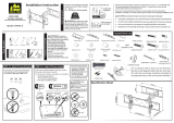
Wood Stud Installation Steel Stud Installation Concrete Installation
Pencil Tape LevelPhillips
Screwdriver
Tape
Measure
Electric Drill
Grab Your Tools
Verify Your Wall Construction
Hex Key
1/2 in.
(13 mm)
Steel Stud Kit required (not included)
"Give it back
to Phil when
you finish"
"collect the
whole set!"
... unless you WANT to
watch your TV fall and
crash onto the floor.
TOY SURPRISE
Inside Every Box
UUHHH ?!?
Included with
the EGHWSS kit
Drill Bit
HK

4
WARNING: DON'T FEED TO CHILDREN
—
This product contains small items that could be a choking
hazard if swallowed. Before starting assembly, verify all parts are included and undamaged. If any parts are
missing or damaged, do not return the damaged item to your dealer; contact Customer Service.
Never use damaged parts!
What’s in the Box
5/16 x 2¾ in.
5/16 in.
Fischer UX10 x 60R
M5 x 25mm
M8 x 25mm M8 x 50mm
M6 x 12mm
M8 x 16mm
M6 x 35mmM6 x 20mm
M8 x 35mm
NOTE: Not all hardware included in this kit will be used.
Parts FOR STEP 1
TV Brackets
TV Screws
(qty. 4 each)
[Only one size fits your TV]
Washer Spacers
[If necessary]
03
02
01
M6/M8
M6/M8
2.5 mm
M6/M8
22 mm
M6
M8
(qty. 1)
04
(qty. 1)
05
(qty. 4)
(qty. 4)
(qty. 8)

5
5/16 x 2¾ in.
5/16 in.
Fischer UX10 x 60R
M5 x 25mm
M8 x 25mm M8 x 50mm
M6 x 12mm
M8 x 16mm
M6 x 35mmM6 x 20mm
M8 x 35mm
Parts FOR STEP 3
5/16 x 2¾ in.
5/16 in.
Fischer UX10 x 60R
M5 x 25mm
M8 x 25mm M8 x 50mm
M6 x 12mm
M8 x 16mm
M6 x 35mmM6 x 20mm
M8 x 35mm
Parts FOR STEP 2
Wall Plate
Lag Screw
Washer
(For Lag Screw)
Drill Hole
Template
Concrete Anchor
Concrete Anchors
For concrete installations ONLY
CAUTION: Do not use in drywall or wood
Fischer UX10 x 60R
Order the Steel Stud Anchor Kit:
Model EGHWSS. Sold online at
ECHOGEAR.com or Amazon.
1/4 in.
1/4-20 Snap Toggle BB
Order the Steel Stud Anchor Kit:
Model EGHWSS
. Sold online at
ECHOGEAR.com or Amazon.
1/4 in.
1/4-20 Snap Toggle BB
(qty. 1)
06
(qty. 1)
07
(qty. 4)
08
(qty. 4)
09
(qty. 4)
10
(qty. 2)
11
13 mm
(1/2 in.)
for steel
Included with
the EGHWSS kit
Drill Bit
S1 (qty. 4) S2 (qty. 4) S3 (qty. 4)
Securement Screw
Parts FOR STEP 2C
** NOT INCLUDED **

6
SPACER NEEDED
b
NO SPACER
a
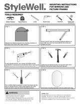
STEP 1 Attach the TV BRACKETS TO YOUR TV
TV Screw Diameter
STEP 1.1
TV Screw Diameter
STEP 1.1
Only one screw size fits your TV.
M6
M8
"
Suggested uses for
the extra screws
:
board game pieces,
industrial jewelry,
sweet corn holders,
musical instruments–
like maracas or
'monsoon' sticks
,
stocking stuers,
currency (not most
countries) ..."
TV Screw Length
STEP 1.2
Long
Screw
Short
Screw
Washer
Washer
Spacer
TV Bracket
TV Bracket
EXTRA
SPACE
Flat Back TV
[TV brackets
04
/
05
lay
flat on your TV]
Flat Back TV
with Extra Space
Needed
[for deep inset holes
or cable interference]
Rounded or
Irregular Back TV
[TV brackets
04
/
05
NOT resting flat on your TV]
01
04
04
05
05
02
02
01
03

7
CAUTION: Ensure TV brackets
04
/
05
are equally
centered on your TV AND securely fastened in place.
Secure the TV Brackets
STEP 1.3
Alternate
Spacer
setups
a
NO SPACER
b
SPACER NEEDED
03
If your TV included
inset spacers or wall
mount adapters, see
Troubleshooting (PAGE 20).
01
01
02
02
05
04

8
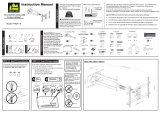
STEP 2 Install the Wall Plate
Max. 16 mm (5/8 in.)
CAUTION: Avoid potential
personal injuries and property damage!
Drywall covering the wall must not
exceed 16 mm (5/8 in.). Minimum
wood stud size: nominal 51 x 102 mm
(2 x 4 in. ) actual 38 x 89 mm
(1½ x 3 ½ in.).
CAUTION: Avoid potential
personal injuries and property damage!
Mount wall plate
07
directly onto the
concrete surface (no surface covering).
CAUTION: Avoid potential personal
injuries and property damage!
● Studs must be at least 2x4 in. / 25 ga.
● If back side of wall is unfinished, drywall
must be installed to a minimum of one
stud left and right of the stud(s) being
used to install the mount
● Drywall must be a minimum of 1/2 in. (13
mm) thick on each side of the studs, and
a minimum clearance of 1 ⅞ in. (48 mm)
behind the wall is required
● Pilot holes MUST be drilled to a depth
of 1 in. (26 mm), using a 1/2 in. (13 mm.)
diameter drill bit
● This product must be centered on the studs
● Stud type and structural strength
must conform to the North American
Specification for the Design of Cold-
Formed Steel Structural Members
[362 S 125 18, C-Shape, S - Stud Section]
● Drywall must be secured to studs with
screws 12 in. (304.8 mm) on center
Min.
203 mm
(8 in.)
Min.
203 mm
(8 in.)
Min.
203 mm
(8 in.)
Min.
406 mm
(16 in.)
Min. Wood Stud Spacing:
406 mm (16 in. )
Min. Wood Stud Width:
nominal 51 mm (2 in.)
actual 38 mm (1
½
in.)
Min. Wood Stud Depth:
nominal 102 mm (4 in.)
actual 89 mm (3
½
in.)
For
CONCRETE
INSTALLATIONS,
follow STEP 2B on PAGE 12
For
STEEL STUD
INSTALLATIONS,
follow STEP 2C on PAGE 14
X-Ray
Specs
sold
separately
For
WOOD STUD
INSTALLATIONS,
follow STEP 2A on PAGE 10

9
(For Wood Stud)STEP 2A Install the Wall Plate
Align the Template
STEP 2A.2
Find a Stud
STEP 2A.1
X-Ray
Specs
sold
separately
"favorite
pokey device"
"come on ...
level with me"
06

10
Drill Holes Secure Wall Plate
STEP 2A.3 STEP 2A.4
Go to STEP 3
on PAGE 16
CAUTION: Avoid potential personal injury or
property damage! All four lag screws
08
MUST BE
firmly tightened to prevent unwanted
movement of the wall plate assembly.
5.5 mm
(7/32 in.)
6.9 cm (
2¾
in.)
Bit
08 09
07
06
06

11
(For CONCRETE)STEP 2B In sta ll the Wall Plate
002862.eps
Align the Template Drill Holes
STEP 2B.1 STEP 2B.2
IMPORTANT: Never drill into the mortar
between blocks.
10 mm
(3/8 in.)
7.6 cm (3 in.)
Bit
"come on ...
level with me"
Min. hole Spacing:
610 mm (24 in.)
06
06

12
Insert Concrete Anchors Secure Wall Plate
STEP 2B.3 STEP 2B.4
Go to STEP 3
on PAGE 16
CAUTION: Avoid potential personal injury or
property damage! All four lag screws
08
MUST BE
firmly tightened to prevent unwanted
movement of the wall plate assembly.
08
09
X-Ray
Specs
sold
separately
10
07
06

13
(For STEEL Stud)STEP 2C Install the Wall Plate
Find a Stud
STEP 2C.1
Drill Holes
STEP 2C.2
X-Ray
Specs
sold
separately
"come on ...
level with me"
25 mm (1 in.)
13 mm
(1/2 in.)
06

14
Install Anchors Secure Wall Plate
STEP 2C.3 STEP 2C.4
CAUTION: Avoid potential personal injury or
property damage! All four lag screws
S2
MUST BE
firmly tightened to prevent unwanted movement of
the wall plate assembly.
a
b
c
d
S2
S1
S3
S1
07
06

15
STEP 3 Hang Your TV
04
07
07
07
04
04
05
05
04
04
05
05
05
Attach Your TV
STEP 3.1
TIP: Tilt TV brackets
04
and
05
as shown for ease of installation.
HEAVY! You may need
assistance with this step.
"Ask that friend of yours that
yammers on about CrossFit"

16
Secure Your TV
STEP 3.2
11
07
05
04
07
IMPORTANT: BEFORE MOVING YOUR TV, securely tighten down screws
11
to properly install the assembly.
CAUTION: Avoid potential personal injuries or property damage! Screws
11
must be installed to secure arms to wall plate
07
. Periodic
tightening may be required.

17
Adjustments
TILTLEVEL
EXTEND / RETRACT
HK
T
Your TV should adjust easily when moved, then stay
in place. If your TV is too loose or too tight, adjust side
tension knobs
T
.
NOTE: Once your TV is in place, tighten the side
tension knobs
T
to prevent unwanted movement.
If your TV doesn't extend or retract
properly, remove your TV (See PAGE 19),
then reinstall following STEP 3 on PAGE 16.
IMPORTANT: BEFORE MOVING
YOUR TV, securely tighten down screws
11
shown on PAGE 17, to properly install
the assembly.
05
05
04
04

18
REMOVING THE TV TV LATERAL SHIFT
Remove your TV BEFORE shifting side-to-side:
1. Loosen screws
11
to remove your TV from the wallplate.
2. Rehang your TV on the wallplate where desired (STEP 3).
3. Reinstall your TV and screws
11
(STEP 3).
2
2
3
1
11
11
11
3
05
04
"Don't be a hero!"
HEAVY! You may need
assistance with this step.
1

19
b: Use your TV supplied spacer and spacer
03
for:
Troubleshooting
TV Supplied
Spacer
TV Supplied
Spacer
TV supplied spacers
CAUTION: Avoid potential injury or property damage!
Use the correct screw length for adequate thread engagment.
CAUTION: Avoid potential injury or property damage!
Use the correct screw length for adequate thread engagment.
TV Supplied
Spacers
a
b
FLAT BACK
ROUND BACK CABLES
– Too short will
not hold the TV.
– Too long will
damage the TV.
– Too short will
not hold the TV.
– Too long will
damage the TV.
Too Short
Too Short
Too Long
Too Long
Correct
Correct
If you are uncertain about your hardware selection,
contact Customer Service
a: Use your TV supplied spacer for flat back TVs (AND you want your
TV closer to the wall).
NOTE:
M8 screws can be used without the washer for extra thread engagement.
● Round (irregular) back TVs ● Extra space needed for cables
NOTE:
M8 screws can be used without the washer for extra thread engagement.
03

Milestone Global Headquarters 6436 City West Parkway, Eden Prairie, MN 55344 USA
“Wanna show o your hard work?
Share a picture of your completed project with #YourGearUpgraded.
Who knows, it might not be as bad as you thought”
Milestone AV Technologies and its aliated corporations and subsidiaries (collectively, “Milestone”), intend to make this manual accurate and
complete. However, Milestone makes no claim that the information contained herein covers all details, conditions, or variations. Nor does it provide
for every possible contingency in connection with the installation or use of this product. The information contained in this document is subject to
change without notice or obligation of any kind. Milestone makes no representation of warranty, expressed or implied, regarding the information
contained herein. Milestone assumes no responsibility for accuracy, completeness or suciency of the information contained in this document.
©2018 Milestone AV Technologies. All rights reserved. ECHOGEAR is a Milestone brand.
ECHOGEAR and the ECHOGEAR logo are trademarks of Milestone. Made in China.
Need Help? Contact the ECHOGEAR Pros:
6901-602302 00
Milestone Global Headquarters
6436 City West Parkway
Eden Prairie, MN 55344 USA
Milestone AV Technologies EMEA Headquarters
Po Box 191, 6000 AD Weert, The Netherlands
Franklinstraat 14, 6003 DK Weert, Netherlands
ECHOGEAR.com
ECHOGEAR.com
helpmehelpyou@ECHOGEAR.com
helpme@ECHOGEAR.com
1-855-428-2490
UK: (0) 00 056 2853
P: +31 (0) 495 580 852
/