Page is loading ...

QLT
K1
INSTRUCTION MANUAL
We’ll Make It Stress-Free
If you have any questions along the way, just give us a call.
US: 800-359-5520 • EMEA P: 0800 056 2853
We’re ready to help!
Scan for easy install video
san.us/1144

2
110 lbs.
(49.8 kg)
Wood Stud Install
Concrete Install
Tape
Measure
Pencil Level
Screw
driver
Electric
Drill
Socket
Wrench
Stud
Finder
Awl
Wood
Drill Bit
Masonry
Drill Bit
Hammer
3/8 in.
(10 mm)
1/2 in.
(13 mm)
7/32 in.
(5.5 mm)
CAUTION: IMPORTANT SAFETY INSTRUCTIONS — PLEASE READ ENTIRE MANUAL PRIOR TO USE — SAVE THESE INSTRUCTIONS
Before getting started, let’s make sure this mount is perfect for you!
Does your TV
(including accessories)
weigh MORE than
110 lbs. (49.8 kg)?
No? Perfect – you may continue.
Yes? This mount is NOT compatible.
Visit secura-av.com or call US: 800-359-5520
EMEA P: 0800 056 2853 to find a compatible mount.
Please read through these instructions completely to be sure you’re comfortable with this easy install process.
Also check your TV owner’s manual to see if there are any special requirements for mounting your TV.
If you do not understand these instructions or have doubts about the safety of the installation, assembly or use
of this product, contact Customer Service.
Do you have
all the tools
needed?
1
2
3
4
What is your
wall made of?
Ready to begin?
Solid concrete or
concrete block?
Perfect!
Drywall with
wood studs?
Perfect!
CAUTION:
DO NOT
install into
drywall alone
Unsure?
Call Customer Service:
?
CAUTION:
DO NOT exceed the maximum weight
indicated. This mounting system is intended for use only
with the maximum weights indicated. Use with products
heavier than the maximum weights indicated may result
in collapse of the mount and its accessories, causing
possible injury.
CAUTION: Avoid potential personal injury or property damage!
● This product is designed for use in wood stud, solid concrete, and concrete block walls - DO NOT install into drywall alone
● The wall must be capable of supporting five times the weight of the TV and mount combined
● Do not use this product for any purpose not explicitly specified by manufacturer
● Manufacturer is not responsible for damage or injury caused by incorrect assembly or use

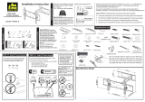
3
Dimensions
TV INTERFACE
WALL PLATE
FULLY ASSEMBLED MOUNT
TOP VIEW - EXTENDED
TOP VIEW - RETRACTED
SIDE VIEW - EXTENDED
SIDE VIEW - RETRACTED
3-D
8.74in
[222mm]
25.59in
[650mm]
5.07in
[129mm]
24.17in
[614mm]
.35in
[9mm]
6.22in
[158mm]
8.03in
[204mm]
16.06in
[408mm]
23.62in
[600mm]
15.98in
[406mm]
7.87in
[200mm]
1.81in
[46mm]
.59in
[15mm]
16.93in
[430mm]
25.59in
[650mm]
1.26in
[32mm]
3.60in
[91.3mm]
5°
8°
10°

4
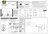
Parts and Hardware
WARNING: This product contains small items that could be a choking hazard if swallowed. Before starting assembly, verify all parts
are included and undamaged. If any parts are missing or damaged, do not return the damaged item to your dealer; contact Customer Service.
Never use damaged parts!
NOTE: Not all hardware included will be used.
Parts and Hardware for STEP 1
M6/M8
5/16 x 2¾ in.
5/16 in.
Fischer UX 10 x 60R
Concrete Anchors
For concrete installations ONLY
CAUTION: Do not use in drywall or wood
M6 x 12mm M6 x 35mm
M8 x 16mm M8 x 35mm
M8 x 20mm
M8 x 50mm
22mm
2.5mm
TV Brackets
TV Screws
M6
M8
Washers
Spacers
02 x4 05 x4
04 x4
06 x4
03 x4
07 x4
08 x4
09 x4
10 x4
01 x2

5
M6/M8
5/16 x 2¾ in.
5/16 in.
Fischer UX 10 x 60R
Concrete Anchors
For concrete installations ONLY
CAUTION: Do not use in drywall or wood
M6 x 12mm M6 x 35mm
M8 x 16mm M8 x 35mm
M8 x 20mm
M6/M8
5/16 x 2¾ in.
5/16 in.
Fischer UX 10 x 60R
Concrete Anchors
For concrete installations ONLY
CAUTION: Do not use in drywall or wood
M6 x 12mm M6 x 35mm
M8 x 16mm M8 x 35mm
M8 x 20mm
Parts and Hardware for STEP 2 Accessories
6 ft HDMI Cable
Surge Protector
Hook and Loop Cable Ties
x1
x1
x5
Washers
(Lag Bolt)
Lag Bolts
Wall Plate
13 x4
14
12 x4
11 x1
x4

6
STEP 1 Attach Brackets to TV
1.1 Select Angle of TV Tilt
Using the preattached angle brackets, TV can be set to either a 10° or 8° tilt.
10° Tilt 8° Tilt

7
For no tilt, remove the preattached angle brackets.
For 5° tilt, remove the
preattached angle brackets,
rotate the brackets as shown
and reattach the brackets.
0° Tilt
5° Tilt

8
FLAT BACK ROUND BACK CABLESINSET HOLES
1.2 Select TV
Screw Diameter
1.3 Select TV
Screw Length
Hand thread screws into the threaded inserts
on the back of your TV to determine which
screw diameter (M6, or M8) to use.
a
b
If your TV has a flat back AND you want your TV closer to
the wall, use the shorter screws (a).
Use the spacers and longer screws (b) to accommodate:
● Round/irregular back TVs
● TVs with inset mounting holes
● Extra space needed for cables
Too Short
Too Long
Correct
Standard configurations
are shown. For special
applications, or if you
are uncertain about your
hardware selection,
contact Customer Service.
CAUTION:
Verify adequate thread
engagement with your screw/
washer/spacer combination
AND TV bracket.
- Too short will not hold the TV.
- Too long will damage the TV.
M6 M8

9
1.4 Attach TV Brackets
a
Flat Back
b
Round Back / Extra Space
Place your TV brackets over your TV mounting holes. Ensure that your TV brackets are level, and vertically centered or close to centered.
Install using the TV screw/washer/spacer configuration you selected for your TV.
CAUTION: Avoid potential personal injuries and property damage! DO NOT use power tools for this step. Tighten the screws only enough
to secure the TV bracket to the TV. DO NOT overtighten the screws.
IMPORTANT: Ensure TV bracket is securely fastened before moving on to the next step.
02 03
05
10
04
08
08
09
01
06 07

10
STEP 2A Attach Wall Plate to Wall
Wood Stud Option
1. Locate your studs. Verify and mark the center of the stud by finding the stud edges using an awl, a thin nail, or an edge to edge stud finder.
2. Position the wall plate
11
at your desired height and line up the holes with your stud center line. Level the wallplate and mark the hole locations.
1
2
11
CAUTION: Avoid potential personal injury or property damage!
● Drywall covering the wall, must not exceed 5/8 in. (16 mm)
● Minimum wood stud size: nominal 2 x 4 in. (51 x 102 mm) actual 1½ x 3½ in. (38 x 89 mm)
● Minimum horizontal space between fasteners: 16 in. (406 mm)
● Stud center must be verified
Max. 5/8 in.
(16 mm)
16 – 24 in.
(406 – 610 mm)

11
4
3
3. Drill pilot holes using a 7/32 in. (5.5 mm) diameter drill bit.
IMPORTANT: Pilot holes must be drilled to a depth of 2¾ in. (70 mm). Be sure to drill into the center of the studs.
4. Install wall plate
11
using four lag bolts
12
and four washers
13
. Tighten the lag bolts only until they are pulled firmly against the wall plate.
CAUTION: Improper use could reduce the holding power of the lag bolt. DO NOT over-tighten the lag bolts.
Go to STEP 3 on PAGE 14.
7/32 in.
(5.5 mm)
2¾
in. (70 mm)
11
13
12

12
1. Position the wall plate
11
on the wall at your desired height. Level the wall plate and mark the hole locations.
2. Drill four pilot holes using a 3/8 in. (10 mm) diameter masonry drill bit.
IMPORTANT: Pilot holes must be drilled to a depth of 3 in. (75 mm). Never drill into the mortar between blocks.
21
002862.eps
11
STEP 2B Attach Wall Plate to Wall
Solid Concrete or Concrete Block Option
CAUTION: Avoid potential personal injury or property damage!
● Mount the wall plate assembly
11
directly onto the concrete surface.
● Minimum solid concrete thickness: 8 in. (203 mm)
● Minimum concrete block size: 8 x 8 x 16 in. (203 x 203 x 406 mm)
● Minimum horizontal space between fasteners: 16 in. (406 mm)
3/8 in.
(10 mm)
3 in. (75 mm)

13
3. Insert four anchors
14
.
CAUTION: Be sure the anchors are seated flush with the concrete surface.
4. Install wall plate
11
using four lag bolts
12
and washers
13
. Tighten the lag bolts only until they are pulled firmly against the wall plate.
CAUTION: Improper use could reduce the holding power of the lag bolt. DO NOT over-tighten the lag bolts.
3
4
11
14
12
13

14
STEP 3 Attach TV to Wall Plate
HEAVY! You may need
assistance with this step.
Hang TV/bracket assembly onto wall plate
11
using predetermined angle (Step 1.1 pages 6-7).
1
11
01

15
Lower the bottom of the TV and press in place.
IMPORTANT: You will hear an audible click when the
TV bracket
01
is securely fastened to the wall plate
11
.
2
01
11
11
11
01
01

16
Adjustments
HEAVY! You may need
assistance with this step.
To remove the TV from the wall plate: Pull down and hold the release straps while swinging the bottom of the TV away from the
wall plate, then lift the TV up and o the wall plate.

17

18
MILESTONE LIMITED WARRANTY AND CONNECTED EQUIPMENT WARRANTY
Product Warranty
Milestone warrants to the original purchaser that the product shall be free of defects in materials and workmanship under normal use for one
year. When this surge protector operates properly and prevents an energy surge from damaging electrical equipment, the surge protective com-
ponent will disconnect from the circuit and you will need to buy a replacement product. This warranty extends only to the original purchaser and
is nontransferable during the warranty period. Milestone will, at no additional charge, repair or replace defective parts or, at its option, replace
the entire unit. This warranty does not extend to any Milestone product that has been damaged or rendered inoperable as intended or defective
(a) as a result of accident, misuse or abuse; or (b) by the use of parts not manufactured or sold by Milestone; or (c) by modification of the product.
Connected Equipment Damage Warranty
Milestone will also provide you with a remedy for damage to connected equipment if (i) you have a claim that is covered by the limited product
warranty described above, and (ii) Milestone receives a formal warranty claim from you before the end of the warranty period for damage to con-
nected applicable to the aected product. If the conditions listed in the preceding sentence are met, Milestone will provide you with one of the
following remedies, provided that it may decide at its sole discretion which remedy it provides. Milestone will (1) replace the damaged connected
equipment; (2) pay to repair the damaged connected equipment; or (3) pay you the fair market value of the connected equipment, provided that
such payments shall not exceed (i) the maximum coverage amount for the product, or (ii) the amount of actual damage caused by power surges
due to a product defect. NOTE: Compensation for restoration of data loss is not covered AND MILESTONE DOES NOT ASSUME ANY LIABILITY
FOR ANY LOSS OF PROFIT, REVENUE OR SAVING (WHETHER DIRECT OR INDIRECT) OR FOR ANY INCIDENTAL, CONSEQUENTIAL OR INDIRECT
DAMAGES UNDER THIS LIMITED WARRANTY. This Connected Equipment Damage Warranty does NOT cover damage caused by lightening or
lightning strikes. Some states do not allow the exclusion or limitation of incidental or consequential damages, so the above limitation or exclu-
sion may not apply to you. THE MAXIMUM AMOUNT OF COVERAGE FOR DAMAGE TO PROPERLY CONNECTED EQUIPMENT IS $1,000. Nothing in
this warranty shall exclude or limit liability for death or personal injury caused by negligence, for fraud or fraudulent misrepresentation or where
exclusion or limitation is not permitted by law.
Other Rights. THESE LIMITED WARRANTIES GIVE YOU SPECIFIC LEGAL RIGHTS, AND YOU MAY ALSO HAVE OTHER RIGHTS. THIS WARRANTY
DOES NOT AFFECT YOUR STATUTORY RIGHTS. THIS WARRANTY EXTENDS ONLY TO YOU, THE ORIGINAL PURCHASER, AND CANNOT BE
TRANSFERRED OR ASSIGNED. If any provision of these limited warranties is unlawful, void or unenforceable, that provision shall be deemed
severable and shall not aect any remaining provisions. In case of any inconsistency between the English and other versions of these limited
warranties, the English version shall prevail.

19
Registration. Please register your Product at www.milestone.com. Failure to register does not aect your warranty rights.
FORMAL WARRANTY CLAIM
How To Make A Claim. In the event damage has occurred to a Milestone product or to connected equipment, you must contact Milestone within
thirty (30) days of the date you knew or should have known of the damages. Follow all instructions for making a claim. THIS REQUIREMENT THAT
YOU NOTIFY MILESTONE WITHIN THIRTY (30) DAYS AFTER YOU DISCOVER OR SHOULD HAVE DISCOVERED A PRODUCT DEFECT AFFECTS AND
LIMITS YOUR WARRANTY RIGHTS.
GENERAL PROVISIONS
Choice of Law/Jurisdiction. These limited warranties and any disputes arising out of or in connection with these limited warranties (“Disputes”)
shall be governed by the laws of England and Wales, excluding the Convention for the International Sale of Goods. The courts located in England
and Wales shall have exclusive jurisdiction over any Disputes.
TO THE MAXIMUM EXTENT PERMITTED BY LAW THESE LIMITED WARRANTIES ARE IN LIEU OF AND IN PLACE OF ALL OTHER EXPRESS OR
IMPLIED WARRANTIES, CONDITIONS AND OTHER TERMS.

Milestone AV Technologies and its aliated corporations and subsidiaries (collectively, “Milestone”), intend to make this manual accurate and complete. However,
Milestone makes no claim that the information contained herein covers all details, conditions, or variations. Nor does it provide for every possible contingency in
connection with the installation or use of this product. The information contained in this document is subject to change without notice or obligation of any kind.
Milestone makes no representation of warranty, expressed or implied, regarding the information contained herein. Milestone assumes no responsibility for accuracy,
completeness or suciency of the information contained in this document.
©2019 Milestone AV Technologies. All rights reserved. Secura is a brand of Milestone. Secura, the Secura logo, and MountFinder are trademarks of Milestone.
Milestone AV Technologies • 6436 City West Parkway • Eden Prairie, MN 55344 USA
Milestone Global Headquarters
6436 City West Parkway
Eden Prairie, MN 55344 USA
800-359-5520
Milestone AV Technologies
EMEA Headquarters
Franklinstraat 14
6003 DK Weert,
Netherlands
P: 0800 056 2853
6901-602421 00
/