Page is loading ...

3600 Flow Monitor
Operation and Maintenance Manual
May 1998 530002A2
An introductory guide to the ADS
3600 intrinsically safe flow monitor
ADS Corporation
4940 Research Drive
Huntsville, AL 35805 USA
(256) 430-3366

Copyright 1998 ADS Corporation
ADS
and QuadraScan
are registered trademarks of ADS Corporation. All other
brand and product names are trademarks or registered trademarks of their respective
holders.
FieldScan
is a trademark of ADS Corporation. All other brand and product names are
trademarks or registered trademarks of their respective holders.
The IBM
Personal Computer is a trademark of International Business Machines
Corporation.
Notice of Proprietary Information
The information contained herein represents the latest information available at the time of publication.
ADS Corporation reserves the right to make any changes or modifications to the content of this document,
without notice, to reflect the latest changes to the equipment. No part of this document may be reproduced
in any form without the written consent of ADS Corporation.

i
Contents
Chapter 1 Introduction 1-1
The ADS Flow Monitoring System .................................................................... 1-3
Flow Monitoring with the QS3600............................................................... 1-3
Intrinsic Safety.................................................................................................... 1-5
Unique Features ............................................................................................ 1-5
Installation and IS Considerations ................................................................ 1-6
Maintenance Restrictions.................................................................................... 1-7
Warnings, Certifications, FCC Compliance, and Conformity............................ 1-8
Intrinsically Safe (IS) Certification............................................................... 1-8
FCC Compliance........................................................................................... 1-8
Additional Notice of Canadian Emissions Requirements........................... 1-10
Declaration of Conformity.......................................................................... 1-10
Chapter 2 Hardware 2-1
Major Components of the QS3600 Monitor ....................................................... 2-3
Processor Board ............................................................................................ 2-3
Sensor Interface Boards ................................................................................ 2-5
Flow Sensors................................................................................................. 2-5
Battery Pack.................................................................................................. 2-5
IS Modem and Telephone Interface Box...................................................... 2-6
External Modem Unit ................................................................................... 2-7
Data Access Arrangement........................................................................... 2-10
Chapter 3 Flow Measurement 3-1
Monitor Operation .............................................................................................. 3-2
Monitor Activation ....................................................................................... 3-2
Flow Sensor Measurement Techniques .............................................................. 3-4
Upstream Installation.................................................................................... 3-4
Quadredundancy ........................................................................................... 3-4
Ultrasonic Depth Sensor ............................................................................... 3-4
Pressure Depth Sensor .................................................................................. 3-5
Doppler Velocity Sensor............................................................................... 3-6
Ultrasonic Depth Data Scrubbing ....................................................................... 3-7
Transmitting Data to the Computer .................................................................... 3-8

ii ADS 3600 Flow Monitor O&M Manual
Confirmation....................................................................................................... 3-8
Chapter 4 Ring, Sensor, and Special Installations 4-1
Preparing for Installation .................................................................................... 4-3
Required Supplies ......................................................................................... 4-4
Ring Assembly.................................................................................................... 4-5
Assembling the Ring..................................................................................... 4-5
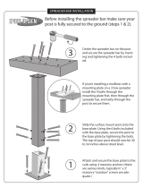
Connecting the Spreader Mechanism ........................................................... 4-8
Quality Control ........................................................................................... 4-11
Non-Overlapping Rings.............................................................................. 4-12
Mounting the Sensors ....................................................................................... 4-13
Mounting an Ultrasonic Sensor .................................................................. 4-13
Mounting a Doppler Velocity Sensor ......................................................... 4-13
Mounting a Pressure Depth Sensor............................................................. 4-14
Connecting Inputs and Outputs......................................................................... 4-16
Installing the Ring............................................................................................. 4-17
Final Sensor Cable Preparation................................................................... 4-19
Special Installations .......................................................................................... 4-20
Required Supplies ....................................................................................... 4-21
Standard Ultrasonic Mount......................................................................... 4-22
Adjustable Ultrasonic Mount...................................................................... 4-27
Surcharge Mount......................................................................................... 4-30
3/4 Band Velocity Mount ........................................................................... 4-34
1/2 Band Velocity Mount ........................................................................... 4-38
Chapter 5 Monitor Installation and Activation 5-1
Installing the EMU.............................................................................................. 5-2
Pavement Box Location................................................................................ 5-3
Underground Services and Lines Location................................................... 5-3
Pavement Box and Cable Trenching............................................................. 5-4
Pavement Box Installation ............................................................................ 5-5
External Modem Unit (EMU) Installation.................................................... 5-8
Communication Cable Installation ............................................................... 5-8
Communication and Telephone Cable Wiring ........................................... 5-12
Direct Connection Communication (SCADA System) .............................. 5-14
Direct Connection Communication (Portable Computer) .......................... 5-15
Baud Rate Setup.......................................................................................... 5-15
Jumper Settings........................................................................................... 5-18
Multiplexor Priority Setting........................................................................ 5-20
Monitor Installation .......................................................................................... 5-22
Telephone Interface Box Installation.......................................................... 5-23

Contents iii
Lightning Protection Module Installation................................................... 5-25
Monitor Activation ........................................................................................... 5-27
Data Collection and Confirmation.................................................................... 5-28
Chapter 6 Monitor Maintenance 6-1
Remote Confidence Checks................................................................................ 6-2
Monitor ......................................................................................................... 6-2
Lightning Protection Module........................................................................ 6-3
Telephone Interface Box............................................................................... 6-3
EMU.............................................................................................................. 6-3
Flow Sensors................................................................................................. 6-4
Maintaining the EMU Batteries.......................................................................... 6-5
Chapter 7 Troubleshooting 7-1
Guidelines ........................................................................................................... 7-2
Troubleshooting .................................................................................................. 7-3
General Monitor Problems............................................................................ 7-3
Ultrasonic Depth Subsystem......................................................................... 7-6
Doppler Velocity Subsystem ........................................................................ 7-8
Pressure Depth Subsystem............................................................................ 7-9
Recommended Spare Parts ............................................................................... 7-11
Appendix A Features and Specifications A-1
General Features and Specifications.................................................................. A-2
Data Storage................................................................................................. A-5
106100 Processor Board .................................................................................... A-6
Depth Subsystem ............................................................................................... A-7
Ultrasonic Depth Sensor .............................................................................. A-7
Pressure Depth Sensor ................................................................................. A-8
Depth Board Digital Specifications ............................................................. A-8
Doppler Velocity Subsystem ............................................................................. A-9
Doppler Velocity Sensor.............................................................................. A-9
Doppler Velocity Board Digital Specifications ........................................... A-9
Communications ............................................................................................... A-10
EMU .......................................................................................................... A-10
SCADA EMU ............................................................................................ A-10
DAA........................................................................................................... A-11

1-1
C H A P T E R 1
Introduction
The ADS
QuadraScan
3600 (QS3600) flow monitor is a compact, microprocessor-
based flow monitor that meets the requirements of intrinsic safety (IS) certification.
(For more information on the QS3600 IS certification, see “Intrinsic Safety” on page
1-5.)
The QS3600 flow monitor is installed in a sewer manhole and is connected by
telephone lines and a modem to a central computer. Installed on the central
computer, ADS QuadraScan software configures and activates the monitor. The
QS3600 flow monitor can then gather data electronically. Using the monitor and
QuadraScan software, this data can be analyzed to measure sewer pipe flow rates and
to generate reports.
The QS3600 flow monitor also performs sampler control, which outputs a discrete
signal to a sampler, and event notification, which alerts you and prints a message
when specified events occur. An additional capability is its capability to be
connected to the rain gauge; a rain gauge records the amount of rain that falls during
a specified time period and allows you to judge the severity of the effect that rain has
on a mini-system.
Using a supervisory control and data acquisition (SCADA) system, the QS3600 flow
monitor can also be configured to measure open channel flow in sewage collection
systems to allow real time monitoring and control of the system.
The QS3600 flow monitor plays an important role in the ADS complete flow
monitoring system. Read “The ADS Flow Monitoring System” on page 1-3 for a
brief explanation of the QS3600’s role in this system.
This manual explains how to install, operate, maintain, and troubleshoot the QS3600
flow monitor. You can find supplemental information on the monitor's specifications
in Appendix A of this manual.
To learn about: See page:
The ADS Flow Monitoring System ........................................................ 1-3
Flow Monitoring with the QS3600................................................... 1-3
Intrinsic Safety........................................................................................ 1-5
Unique Features ................................................................................ 1-5
Installation and IS Considerations .................................................... 1-6
Maintenance Restrictions........................................................................ 1-7

1-2 ADS 3600 Flow Monitor O&M Manual
Warnings, Certifications, FCC Compliance, and Conformity................ 1-8
Intrinsically Safe (IS) Certification................................................... 1-8
FCC Compliance............................................................................... 1-8
Additional Notice of Canadian Emissions Requirements................. 1-9
Declaration of Conformity.............................................................. 1-10

Introduction 1-3
The ADS Flow Monitoring System
The ADS flow monitoring system is a comprehensive and sophisticated system that
uses powerful scientific and engineering concepts to measure and monitor open
channel flows. The system was initially developed in the late 1970s and has been
used to address a variety of issues faced by municipal sewer systems, such as:
planning sewer systems (for example, sewer sizing, and sewer rehabilitation),
reducing infiltration and inflow (I/I),
monitoring combined sewer overflows (CSO),
monitoring surcharges,
calculating billings, and
monitoring sewage handling facilities (such as wastewater treatment plants
and pump stations).
Flow Monitoring with the QS3600
The main role of the QS3600 flow monitor in the ADS flow monitoring system is to
measure the flow rates in sewer lines. In this application, readings are taken by flow
sensors installed in the sewer pipe, then gathered and processed by flow monitors
connected to the sensors and installed in the manhole. Using a telephone line, the
data is transmitted to the central computer via a modem and then processed by
QuadraScan software. QuadraScan uses the data to generate reports on the quantity
of flow.

1-4 ADS 3600 Flow Monitor O&M Manual
Typical 3600 Flow Monitor Installation
Typically, the monitor is attached to the inside wall of a manhole using bolts. Depth
and velocity flow sensors are installed in the sewer pipe to gather flow data. The
sensors are mounted on a stainless steel ring, usually placed upstream in the sewer
pipe. Cables connect the monitor in the manhole to the sensors in the sewer pipe. The
QS3600 flow monitor is linked to a central IBM-compatible personal computer with a
voice-grade telephone line and either an IS modem or an external modem unit
(EMU). (Data can also be acquired serially directly from the monitor with an
internal IS modem). This link allows you to communicate with the monitor,
configure the monitor, activate the monitor, collect data, and perform monitor
diagnostics from a remote location.
In order to measure the flow rate in a sewer pipe, the QS3600 flow monitor gathers
data on the depth and/or velocity of the flow. The monitor gets this data by
periodically scanning the sensors which are installed in the pipe. The monitor uses
two types of sensors to determine the depth of flow: the ultrasonic depth sensor and
the pressure depth sensor. The monitor has a Doppler velocity sensor to measure
flow velocity. See Chapter 2 for information on the monitor’s key hardware
components. See Chapter 3 for a more detailed explanation of monitor operation.

Introduction 1-5
Intrinsic Safety
Intrinsic safety (IS) is a special certification awarded to equipment when its design
and manufacture meet the high standards of IS regulations . The main goal of IS
regulations is to prevent the electronic equipment from causing explosions in
potentially explosive environments. These environments are categorized as Class I,
Division 1, Groups C and D in the USA and as Zone 0 in Europe; the QS3600 flow
monitor is certified for use in these environments. IS regulations were created by
local and international standards organizations to regulate all electronic equipment
that operate in areas where hazardous gases are present (for example, in sewer
systems).
ADS field crews are trained to test all manholes for the presence of explosive gases
by sampling its atmosphere with a gas meter. When the amount of gas present
exceeds certain limits, the crew does not enter the manhole.
However, a flow monitor is mounted in a manhole for extended periods of time.
During this time, the amount of combustible gas may rise to dangerously high levels
without the field crew's knowledge. As a result, many cities require that all electronic
equipment installed in sewers be tested and certified as non-explosive. ADS
produces the QS3600 IS flow monitor to meet these requirements.
Unique Features
The QS3600 flow monitor can be configured in two ways: by using a monitor with an
internal IS modem or by using a monitor with an external modem unit (EMU).
Country specific telecommunications standards and certifications will dictate whether
the internal IS modem or EMU is required. The external modem unit (EMU) houses
the modem and the power supply outside of the monitor and the manhole. The EMU
contains special circuitry to protect the circuits entering the hazardous area.
Special features of the QS3600 flow monitor include the following.
All QS3600 flow monitors are checked carefully before being shipped. Each
component is guaranteed to meet specifications. The pre-shipping inspection
is completed by internal quality inspectors.
All QS3600 flow monitors connect to 3600 compatible sensor cables. The
female connector is located on the flow monitor lid, while the male connector
is found on the sensor cables (unlike other ADS monitors). This arrangement
of connectors prevents mismatching with non-IS sensors. .
The monitor can be equipped with either an internal IS modem and telephone
interface box or with an external modem unit (EMU).
For the internal IS modem, cables are routed from the monitor to a phone
line interface box located on a pedestal or on the telephone pole. The

1-6 ADS 3600 Flow Monitor O&M Manual
monitor cables and the phone lines connect within this interface box
because IS standards require that telephone lines not be routed directly into
a manhole since it is a potentially explosive environment. An additional
precaution can be taken by using an ADS lightning protection module that
is located above the phone line interface box on the pedestal or telephone
pole and which stops high voltages before they reach the interface box.
An alternative to the internal IS modem is the external modem unit(EMU).
Two types of EMUs are available: one with an internal battery power
source and one which uses an external power source. The same IS
standards apply to the EMU which houses both the monitor's modem and
modem battery outside of the manhole. The EMU is either installed in an
above-ground customer supplied box, in a specially dug pit, or in a
pavement or sidewalk box. A cable then connects the EMU with the
monitor to allow communications between the monitor and a central
computer.
Only limited field repairs to the QS3600 are allowed; all other repairs must be
performed by an authorized technician. For information on allowable field
repairs, see “Maintenance Restrictions” on page 1-7.
Installation and IS Considerations
When installing the QS3600 flow monitor, carefully follow any local regulations for
the installation of IS equipment. For example, many cities only allow the use of IS-
certified flash lights in manholes. Some cities will not allow the use of an electric
drill–either battery powered or AC powered–in a manhole. In this case, air
(pneumatic) tools must be used.

Introduction 1-7
Maintenance Restrictions
As mentioned earlier, all ADS QS3600 flow monitors are manufactured to meet IS
standards. The monitor’s IS certification can be voided instantly if proper
maintenance and service procedures are not followed. ADS must restrict certain
maintenance tasks to ADS IS certified technicians.
ADS allows you to perform only those maintenance tasks which do not require
opening the monitor housing. All other maintenance must be performed by ADS IS-
certified technicians. ADS technicians carefully inspect and document their repairs to
IS monitors. This inspection and documentation process provides legal protection
should the monitor's performance or safety be questioned. It is important to
understand that if the monitor’s housing is opened by unauthorized personnel, the IS
certification is compromised.
For your convenience, ADS allows you to
install and swap monitors,
install and swap sensors,
clean sensors,
calibrate and confirm monitors, and
collect data.
Note: Please note that in all applications, only ADS Service Technicians are
authorized to perform component-level service on the QS3600.
This manual contains the correct procedures for performing routine installation and
maintenance on the QS3600. If you have any question about the procedures, or
regarding the level of service you are allowed to perform on a monitor, contact your
regional ADS office.

1-8 ADS 3600 Flow Monitor O&M Manual
Warnings, Certifications, FCC Compliance, and
Conformity
Changes or Modifications Changes or modifications to the QS3600 flow
monitor not expressly approved by the party responsible for compliance will void the
IS certification.
Personnel performing installation of the QS3600 flow monitor should carefully
follow the guidelines contained in this manual when installing and maintaining the
monitor. Failure to strictly adhere to these guidelines can result in personal injury
and can cause damage to the monitor, which would invalidate its warranty.
The QS3600 flow monitor is designed to be installed in combined and sanitary sewer
lines and manholes. This installation work is inherently dangerous. All applicable
safety guidelines should be followed and carried out by at least two fully trained and
qualified persons.
Intrinsically Safe (IS) Certification
Only authorized technicians can make certain repairs to the QS3600 IS flow monitor.
These repairs must be re-inspected by approved inspectors for continued IS
certification. If individuals other than approved technicians make the repairs, they
will void the monitor’s IS certification. For more information on allowable field
repairs, see “Maintenance Restrictions” on page 1-7.
FCC Compliance
To comply with the Federal Communications Commission (FCC), ADS
Environmental Services provides the following information about installing and
operating the 3600 internal modem DAA/3600 Monitor.
FCC Part 68 This equipment complies with FCC Rules, Part 68. It bears a label
displaying, among other information, the FCC registration number and ringer
equivalence number (REN). The user must provide this information to the telephone
company if requested.
The REN identifies the number of devices that may be connected to the telephone
line. Excessive RENs on the telephone line may prevent devices from ringing in
response to an incoming call. In most areas, the sum of the RENs should not exceed
five. To determine the number of devices you may connect to a line, as determined
by the RENs, contact your telephone company.
This equipment uses standard RJ11C jacks/plugs for connection to the telephone
network. These modular jacks/plugs are FCC compliant. They are designed for

Introduction 1-9
connection to the telephone network or premises wiring using compatible modular
jacks/plugs and cabling that comply with FCC Part 68 rules.
The telephone company may make changes in its facilities, equipment, operations, or
procedures that could affect the operation of this equipment. If this occurs, the
telephone company will provide advance notice so you can make the modifications
necessary to maintain uninterrupted service. In the unlikely event that this equipment
harms the telephone network, the telephone company will notify you that temporarily
discontinuing telephone service may be required. Notification will occur in advance
of discontinuation, or as soon as practically possible. They also will inform you of
your right to file a complaint with the FCC if necessary.
This equipment may not be used on public coin phone service provided by the
telephone company. Connection to party line service is subject to state tariffs.
This equipment is not field repairable. If you experience trouble with this equipment,
please refer to this manual for troubleshooting, replacement, or warranty information
or contact:
ADS Corporation
5030 Bradford Drive, Building 1, Suite 210
Huntsville, AL 35805
(256) 430-3366
FCC Part 15 This equipment has been tested and found to comply with the limits
for a Class A digital device pursuant to Part 15 of the FCC rules. These limits are
designed to provide reasonable protection against harmful interference in a residential
installation. This equipment generates, uses, and can radiate radio frequency energy
and if not installed and used in accordance with the instructions, may cause harmful
interference to radio communications. However, there is no guarantee that
interference will not occur in a particular installation. If this equipment does cause
harmful interference to radio or television reception (which can be determined by
turning the equipment off and on), you should try to correct the interference by one or
more of the following measures:
reorient or relocate the radio or television antenna,
move and/or increase the distance between the computer and the radio or
television, and
plug the computer in an outlet different than the radio or television.
If these suggestions do not help, consult ADS Corporation or an experienced
radio/television technician.
Additional Notice of Canadian Emissions Requirements
This digital apparatus does not exceed the Class A limits for radio noise emissions
from digital apparatus, which were set out in the Radio Interference Regulations of
the Canadian Department of Communications.

1-10 ADS 3600 Flow Monitor O&M Manual
Le present appareil numerique n'emet pas de bruits radioelectriques depassant les
limites applicables aux appareils numeriques (de la class A) prescrites dans le
Reglement sur le brouillage radioelectrique edicte par le ministere des
Communications du Canada.
Declaration of Conformity
For European (EC member country) applications, a Declaration of Conformity is
required to be kept on file at the facility responsible for repair and maintenance of
this equipment. If you have any questions about the Declaration of Conformity,
contact your regional ADS representative.
Sample Declaration of Conformity

2-1
C H A P T E R 2
Hardware
The QS3600 flow monitor is housed inside a cylindrical aluminum canister that is 62
cm (24 in.) long and 17 cm (6.6 in.) in diameter. The canister lid contains ultrasonic,
pressure, velocity sensor, and communication cable connections as well as rain gauge
and sampler communication cable connections. With the lid in place, the canister is
airtight and waterproof.
Warning
: Only ADS Service Technicians are authorized to perform
component level service on the QS3600. If the monitor’s housing is opened by
unauthorized personnel, its IS certification is compromised.
A one-piece chassis attaches to the inside of the monitor lid to provide a mounting
surface for the central processing board (CPU board), the depth interface (for the
ultrasonic level sensor and the pressure depth sensor boards), the velocity interface
(for the Doppler velocity sensor board), and the power supply board (with the internal
modem).
Assembly of the QS3600 IS Flow Monitor
(1) Aluminum Canister (2) Battery Pack
(3) Lid Assembly (4 ) Screw to Attach Battery Pack (5) Foam Insert

2-2 ADS 3600 Flow Monitor O&M Manual
Note: The depth board and velocity boards are also called the input/output
(I/O) boards.
Opening the lid of the monitor and removing the lid assembly reveals the one-piece
chassis. The processor board is mounted to the chassis on the bottom of one side.
Two Doppler velocity boards are mounted on top of the processor board. The depth
board is mounted to the other side of the chassis' frame. The IS modem is located on
the power supply board which is mounted on top of the depth board. The processing,
depth, and velocity boards are connected with a ten-conductor ribbon cable.
A 9 V battery pack is attached to the bottom of the chassis. Cabling connects the
battery pack to the power supply board. The bottom of the housing is sealed.
Connectors for the following cables are installed on the lid of the canister:
the ultrasonic depth sensor cable,
the Doppler velocity sensor cable,
the pressure depth sensor cable,
the communications cable,
the rain gauge cable, and
the sampler cable.
The monitor can be sealed after the lid assembly is securely placed in the monitor.
To learn about: See page:
Major Components of the QS3600 Monitor .........................................2-3
Processor Board.............................................................................2-3
Sensor Interface Boards .................................................................2-5
Flow Sensors..................................................................................2-5
Battery Pack...................................................................................2-5
IS Modem and Telephone Interface Box.........................................2-6
External Modem Unit.....................................................................2-7
Data Access Arrangement ............................................................2-10

Hardware 2-3
Major Components of the QS3600 Monitor
The major components of the QS3600 flow monitor include the processor board, the
sensor interface boards, the battery pack, and the flow sensors. Refer to Appendix A
for additional information regarding these components.
Processor Board
The processor board contains the central processing unit (CPU). It is mounted on the
bottom of the chassis card frame plate which is installed on the lid assembly chassis.
The processor board is the center of all monitor activity, and is responsible for all of
the monitor's high-level functions, including
communications with the central computer,
communications with the sensor interface (I/O) boards,
data storage, and
time-keeping.

2-4 ADS 3600 Flow Monitor O&M Manual
Side View of Flow Monitor Chassis and Assembly
The board allocates portions of memory to firmware (permanently stored software),
data storage, and program manipulation and calculations. A light-emitting diode
(LED) is located on the processor board and indicates the monitor's communication
status. When the processor board is involved in external communications, the LED is
ON. A second LED is used to indicate the current activity level of the processor
board: the brighter the light, the more work the processor board is doing. Discrete
input and output ports, a monitor clock, and a memory battery are also located on the
board.

Hardware 2-5
The processor board performs many functions; it
powers up each input board and provides each board with the parameters
required to carry out the appropriate operations,
periodically scans the sensor interface boards and the optional rain gauge input
to retrieve and store data readings,
outputs a discrete signal to a sampler,
transmits the stored data to the central computer for processing by
QuadraScan software after data is collected, and
maintains the date and time.
Sensor Interface Boards
The QS3600 flow monitor's chassis can hold up to two sensor interface subsystems:
one Doppler velocity subsystem which consists of two boards and
one depth subsystem which consists of one board that is used for both the
pressure depth sensor and the ultrasonic level sensor.
Each sensor interface subsystem communicates with its particular sensor(s) in order to
provide the instructions necessary to collect the appropriate data, collect sensor
readings, and convert raw data to engineering units of measurement (instead of binary
counts).
Flow Sensors
As mentioned earlier, a QS3600 flow monitor can have up to three flow sensors: one
Doppler velocity sensor, one ultrasonic depth sensor, and one pressure depth sensor.
These flow sensors are mounted on an expandable stainless steel ring that is placed in
the sewer pipe upstream from a manhole. Cables connect each sensor to its interface
board through connectors on the monitor's lid.
Battery Pack
The 9 V battery pack provides the power necessary to operate the monitor and
maintain the monitor memory. The monitor measures the battery voltage and signals a
warning when the power is low. The QS3600 battery pack (part number 106152)
meets IS requirements.
/