Page is loading ...

Manual
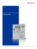
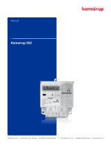
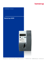
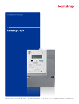
Kamstrup 351B
Kamstrup A/S · Industrivej 28, Stilling · DK-8660 Skanderborg · T: +45 89 93 10 00 · in[email protected] · kamstrup.com

2 Kamstrup A/S • 5512768_C2_GB_01.2015
Kamstrup 351B
Operting instructions
Connect the meter in ccordnce with the instlltion digrm on the meter’s type lbel.
Depending on the configurtion fixed vlue will be displyed, or the disply will chnge between
selected indictions every 10 seconds.
It is possible to chnge the disply reding mnully by ctivting the push button on the meter.
The vilble redings will depend on the meter’s configurtion.
Security nd instlltion guidelines
The meter is only to be used for mesuring electricl energy nd shll operte within the specified
vlues only.
The meter must be disconnected when working on it. It cn be highly dngerous to touch the meter
prts when the meter is switched on.
Therefore, the relevnt security fuse must be removed nd kept in plce where it cnnot be
inserted by unuthorized persons.
Current locl stndrds, guidelines, regultions nd instruction must be observed. Only uthorized
personnel is permitted to instll electricity meters.
Meters for indirect connection must be protected ginst short circuit by security fuse in
ccordnce with the mximum current stted on the meter ≤ 10A.
Utility sels
LCD-disply
Opticl interfce
LED (meter constnt)
Push button
Type lbel
The meter constnt LED blinks proportionlly to the consumed primry ctive energy.
Only uthorized personnel must brek the utility seling.

3Kamstrup A/S • 5512768_C2_GB_01.2015
Kamstrup 351B
LCD disply
The phse indictions L1, L2 nd L3 hve more thn one function, they indicte one of three
situtions described below:
Segments L1- L3 Indicte
On Both voltge nd lod bove minimum limit.
Active phses indicte consumption.
Off The voltge is below minimum limit.
Blinking Segments L1 – L3 function s lod indictors. Voltge is bove nd lod is
below minimum limit.
The lod indictor is ctive 4 hours fter meter reset.
If input nd output hve been switched on the single mesuring system, the
segments L1 - L3 will keep flshing even though there is lod on the phse.
If the lod exceeds the minimum limit nd the meter is configured with this reding, consumption
will be indicted vi the qudrnt reding.
The meter’s LED cn be used provided tht the qudrnt indictor is not selected.
The mesured unit is displyed in the right side of the disply.
Triff indicting ctive triff.
L1 T1 T2 T3 T4
7-digit identifiction field
Qudrnt reding
Sttus reding
Unit field
Triff reding
Phse indiction
Vlue field
Terminls
Size: 2,5 – 10 mm2
Screw: Ph 2 / 6x1 mm
Torch: 2,5 – 3 Nm

4 Kamstrup A/S • 5512768_C2_GB_01.2015
Kamstrup 351B
Instlltion dimensions
2A
S0
P+
-
+2120 117 8 95 62 3 4
L1
1
L2
L3
N
KAMSTRUP 351B
685-35C-B4-33-010
Sn: 1002680 2009W46
3x 230/400V 50Hz
0,05-5(6)A
Kl. C EN 50470-1/3
A
ctive
Kl. 2 EN 62053-23 Reactive
S0: 5000 imp/kWh(kvarh) 5/5
LED: 10000 imp/kWh(kvarh)
-40 - +70°C T10224
* 1 0 0 2 680 *
201,6
166,9
201,5
166,9
Connection digrms
The vlid connection digrm ppers from the type lbel.
3-phse, 4-wire 3-phse, 3-wire (Aron)
≤10A
S0
P+
-
+212011
7 8 9
5 6
2 3 4
L1
1
L2
L3
N
≤10A
S0
P+
-
+21207 8 9
5
2 3
L1
1
L2
L3
/