Kamstrup 351C Installation and User Guide
- Category
- Car kits
- Type
- Installation and User Guide

Installation manual
Kamstrup 251C / 351C / 451C
Kamstrup A/S · Industrivej 28, Stilling · DK-8660 Skanderborg · T: +45 89 93 10 00 · in[email protected] · kamstrup.com

2 Kamstrup A/S • 55121284_D2_GB_01.2015
Kamstrup 251C / 351C / 451C
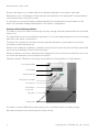
Connect the meter in ccordnce with the instlltion digrm on the meter’s type lbel.
Depending on the configurtion fixed vlue will be displyed, or the disply will chnge between
selected indictions every 10 seconds.
It is possible to chnge the disply reding mnully by ctivting the left push button on the
meter. The vilble redings will depend on the meter’s configurtion.
Security nd instlltion guidelines
The meter is only to be used for mesuring electricl energy nd shll operte within the specified
vlues only.
The meter must be disconnected when working on it. It cn be highly dngerous to touch the meter
prts when the meter is switched on.
Therefore, the relevnt security fuse must be removed nd kept in plce where it cnnot be
inserted by unuthorized persons.
Current locl stndrds, guidelines, regultions nd instruction must be observed. Only uthorized
personnel is permitted to instll electricity meters.
Meters for indirect connection must be protected ginst short circuit by security fuse in ccord-
nce with the mximum current stted on the meter.
Filing to obey the ”Guidelines for sfety nd instlltion”, the gurntee no longer pplies.
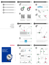
LCD-disply
Opticl interfce
LED (meter constnt)
Push button
(not used)
Utility sels
Type lbel
Secondry module
Push button
The meter constnt LED blinks proportionlly to the consumed ctive secondry energy.
Only uthorized personnel must brek the utility seling.

3Kamstrup A/S • 55121284_D2_GB_01.2015
Kamstrup 251C / 351C / 451C
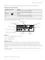
The phse current nd the supply voltge indictions indicte situtions described below.
From the connection of the meter:
Indictions L1, L2, L3 Indicte
On Voltge is bove minimum limit (160 V)
Off Voltge is below minimum limit (160 V)
Indictions Indicte
On The lod is bove the minimum (0.6 W)
Off The lod is below minimum limit (0.6 W)
If the lod exceeds the minimum limit nd the meter is configured with this reding, consumption
will be indicted vi the qudrnt reding. The direction of the three phse currents is indicted vi
the rrows bove, respectively L1, L2 nd L3.
Text field
Unit field
7-digit identifiction field
Qudrnt indictor
Triff indiction Error symbol
9-digit vlue field
Phse current indiction
Supply voltge indiction
Terminls
Size: 2.5-10 mm2 elevting connections
Screw: Ph 2 / 4x1 mm
Torch: 1.8 Nm +/- 10%
With built-in rdio
If the meter is supplied with integrl rdio for estblishment of remote reding, the meter uto-
mticlly connects to rdio network. The integrl rdio is equipped with n internl ntenn.
The rdio signl strength cn be red by mens of hnd-held terminl. If the rdio signl is not
sufficient, n externl ntenn must be connected. Plese see current documenttion on vilble
ntenns.
Mounting communiction module in the meter my influence on rdio communiction, plese
contct Kmstrup.

4 Kamstrup A/S • 55121284_D2_GB_01.2015
Kamstrup 251C / 351C / 451C
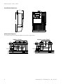
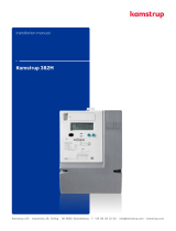
Instlltion dimensions
80,3
171,7
269,2
Connection digrms
The vlid connection digrm ppers from the type lbel.
3-phse, 4-wire 3-phse, 3-wire (Aron)
≤
10A
S0
P+
-
+2120 117 8 95 62 3 4
L1
1
L2
L3
N
S0
P+
-
+2120 7 8 952 3
L1
1
L2
L3
≤
10A
-
 1
1
-
 2
2
-
 3
3
-
 4
4


Kamstrup 351C Installation and User Guide
- Category
- Car kits
- Type
- Installation and User Guide
Ask a question and I''ll find the answer in the document
Finding information in a document is now easier with AI
Related papers
-
Kamstrup FlowIQ Installation guide
-
 Kamstrup CALL function Network registration Installation guide
-
 Kamstrup Valve Quick start guide
-
 Kamstrup flowIQ® 2101 Installation and User Guide
-
 Kamstrup 351B Installation and User Guide
-
 Kamstrup OMNIPOWER® CT meter Installation and User Guide
-
 Kamstrup 162M Installation and User Guide
-
 Kamstrup 382M Installation and User Guide
-
 Kamstrup 162J Installation and User Guide
-
 Kamstrup 382J Installation and User Guide


