Page is loading ...

FORTIS BULLNOSE FRONT BUMPER
2010-18 RAM 25-3500
Page 1 of 5 2/25/21 (DP)
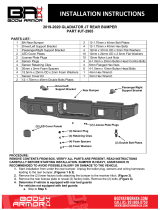
PARTS LIST:
1
Fortis Front Bumper
12
12mm x 37mm x 3mm Large Flat Washers
1
Driver/left side Frame Bracket
16
12mm x 32mm x 3mm STD Flat Washers
1
Passenger/right side Frame Bracket
8
12mm Lock Washers
1
Driver/left side LED Light “L” Bracket
8
12-1.75mm Hex Nuts
1
Passenger/right side LED Light “L” Bracket
6
12mm Nylon Lock Nuts
2
License Plastic Plugs
2
8-1.25mm x 25mm Hex Bolts
3
Dodge Wiring Harnesses
2
8-1.25mm x 16mm Hex Bolts
6
Retaining Ring
6
8mm x 24mm x 2mm Flat Washers
6
Foam Seal Washers
4
8mm Lock Washers
6
Sensor Hole Plugs
2
8-1.25mm Hex Nuts
1
Sensor Cover Kit
12
4mm x 10mm Button Head Screws
14
12-1.75mm x 50mm Hex Bolts
1
2.5mm Wrench
PROCEDURE:
REMOVE CONTENTS FROM BOX. VERIFY ALL PARTS ARE PRESENT. READ INSTRUCTIONS
CAREFULLY BEFORE STARTING INSTALLATION. BUMPER IS HEAVY, ASSISTANCE IS HIGHLY
RECOMMENDED TO AVOID POSSIBLE INJURY OR DAMAGE TO THE VEHICLE. CUTTING MAY BE
REQUIRED.
1. Remove the license plate and bracket. On models with factory fog lights and/or sensors, unplug wiring
harness leading to bumper, (Figure 1). Release the harness from the clips attached to the back of the
bumper and move harness away from bumper.
2. Next, open hood and remove the plastic cover between the top of the grille and the top of the radiator,
(Figure 2). Carefully remove the grille assembly, (Figure 3).
3. Place blocks or jack stands under the front bumper to support it during mounting bolt removal. Once the
bumper has been safely supported, remove the hex nuts attaching each side of the bumper to the
brackets on the end of the frame, (Figure 4). WARNING! Assistance is required to hold the bumper in
place during hardware removal to prevent it from falling. Slide the bumper off of the tow hooks.
4. Next, remove the tow hooks from the end of the frame, (Figures 5 & 6).
5. Select the driver/left Frame Bracket. Attach the Bracket to the end of the frame with (4) 12mm x 50mm
Hex Bolts, (8) 12mm x 32mm STD Flat Washers, (4) 12mm Lock Washers and (4) 12mm Hex Nuts,
(Figure 7). Leave hardware loose. Repeat this Step to install the passenger/right Frame Bracket.
(2) Plastic Plugs
Right LED Light
“L” Bracket
Left LED Light
“L” Bracket
Passenger/Right
Frame Bracket
Driver/Left side
Frame Bracket
(6) Sensor
Hole Plugs
(3) Dodge Wiring
Harnesses
(6) Foam Front Washers
(6) Retaining Clips

FORTIS BULLNOSE FRONT BUMPER
2010-18 RAM 25-3500
Page 2 of 5 2/25/21 (DP)
6. Center LED light installation, (not included, light sold separately). NOTE: It may be easier to install
light in Bumper before attaching Bumper to vehicle.
a. Select the L/R “L” Brackets, (Figure 8). NOTE: “L” Brackets are offset for universal fitment for most
LED bar style lights.
b. Attach the brackets to the tabs on the back of the Bumper with the included (2) 8mm x 25mm Hex
Bolts, (4) 8mm Flat Washers, (2) 8mm Lock Washers and (2) 8mm Hex Nuts, (Figure 8).
c. Attach the LED light assembly to the “L” Brackets with the included (2) 8mm x 16mm Hex Bolts, (2)
8mm Lock Washers and (2) 8mm Flat Washers, (Figure 8). Do not fully tighten hardware at this
time. NOTE: “L” Brackets may require modification for hardware larger than 8mm or use brackets
supplied with light if possible.
d. Adjust light position and tighten hardware.
e. Follow light manufacturer’s instructions to wire the light to the vehicle’s electrical system.
7. Determine of vehicle is equipped with parking sensors. NOTE: Sensors, (if equipped), must be
installed in Bumper before Bumper is attached to Brackets.
Models without bumper sensors:
a. Select the included (6) Rubber Plugs.
b. From behind bumper, push plugs into sensor mounts, (Figure 9). Screws have been provided to
lock the plugs in the mount, use is optional.
Models with bumper mounted sensors:
a. Remove sensors and wiring harness from back of OE Bumper.
b. Select the driver/left outer sensor. Remove the factory sealing washer from the front of the sensor.
Slide the provided Foam Washer onto the front of the sensor, (Figure 10).
c. Push the sensor in from the back of the Bumper until it is flush with the Bumper. NOTE: Sensor
tabs may need to be trimmed to fit sensor inside sensor mount. Push (1) Retaining Clip into the
mount to secure the sensor in place, (Figure 11).
d. Repeat the previous steps to install the remaining sensors.
e. Starting on the driver/left side, run the OE sensor wire harness through the bumper cutouts.
Connect the first three driver/left sensors to the OE sensor wire harness.
f. Use the provided wire harness extensions to connect the wire harness to the remaining three
passenger/right side sensors.
8. With assistance, position the Bumper Assembly up to the insides of the Frame Brackets. Temporarily
support the weight of the Bumper. WARNING: To avoid possible injury or damage to the vehicle, do not
proceed until the Bumper is fully and safely supported.
9. Attach the Bumper to the inside of the Frame Brackets with (6) 12mm x 50mm Hex Bolts, (12) 12mm x
37mm Large Flat Washers and (6) 12mm Nylon Lock Nuts, (Figures 12 & 13). Do not fully tighten.
10. Level and adjust the bumper and fully tighten all hardware.
11. Plug in the bumper harness if equipped, to the main wiring harness.
12. LED light installation at ends of bumper (lights not included, sold separately).
a. Follow the light manufacturer’s instructions to attach each light to slot in the bottom of the light
opening. Check for clearance between front and back of light, (Figure 14).
b. IMPORTANT: On two lights per side systems, attach the flood light to the outer slot and the spot
light to the inner slot.
c. Repeat the above steps for passenger/right side light installation.
d. Follow light manufacturer’s instructions to properly wire the light to the vehicle electrical system.
13. If front license plate is required, insert (2) Plastic Plugs into the square holes in the front of the Bumper,
(Figure 15). Reuse the factory screws to attach the license plate to the plastic plugs.
14. Do periodic inspections to the installation to make sure that all hardware is secure and tight.
To protect your investment, Do not use any type of polish or wax that may contain abrasives that could damage the
finish. Mild soap may be used to clean the Bumper assembly.

FORTIS BULLNOSE FRONT BUMPER
2010-18 RAM 25-3500
Page 3 of 5 2/25/21 (DP)
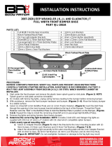
Driver/left Side Installation Pictured
WARNING! Do not remove bumper bolts
unless the bumper is properly supported
on blocks or stands or it may fall.
(Fig 2) Open hood and remove plastic cover
(Fig 1) Unplug lights and sensors if equipped.
Unplug harness to bumper and move harness
(Fig 3) Temporarily remove plastic
grille to access top bumper bolts
(Fig 5) Remove tow hook (Driver side pictured)
Front
Front
Front
(Fig 4) Remove hex nuts from bumper bolts (arrows).
Bumper bracket pictured from below/behind bumper
Front

FORTIS BULLNOSE FRONT BUMPER
2010-18 RAM 25-3500
Page 4 of 5 2/25/21 (DP)
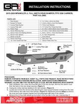
Driver/left Side Installation Pictured
(Fig 6) Tow hook removed from driver side
Front
(Fig 7) Attach Frame Bracket to the
frame (driver/left side illustrated)
(4) 12mm x 50mm Hex Bolts
(8) 12mm x 32mm Flat Washers
(4) 12mm Lock Washers
(4) 12mm Hex Nuts
Front
(2) 8mm x 16mm Hex Bolts
(2) 8mm Lock Washers
(2) 8mm Flat Washers
(Fig 8) Example of center light installation
Front
(2) 8mm x 25mm Hex Bolts
(4) 8mm Flat Washers
(2) 8mm Lock Washers
(2) 8mm Hex Nuts
Right “L”
Bracket
Left “L”
Bracket
(Fig 10) Replace factory seal
washer with Foam Washer
(Fig 9) Insert Plug into sleeve on back of bumper
Front

FORTIS BULLNOSE FRONT BUMPER
2010-18 RAM 25-3500
Page 5 of 5 2/25/21 (DP)
Driver/left Side Installation Pictured
Front
(Fig 12) Driver/left side Frame Bracket
attached to mounting plate on Bumper
(3) 12mm x 50mm Hex Bolts
(6) 12mm x 37mm Flat Washers
(3) 12mm Nylon Lock Nuts
WARNING! Do not crawl under bumper
unless it is properly supported on blocks or
stands or the bumper may fall.
(Fig 14) Outer light mounting brackets
(Fig 11) Push sensor into sensor mount
Foam Washer
Retaining Clip
Front
(Fig 13) Driver/left side complete installation
Front
(Fig 15) Attach license plate Plugs in Bumper
(2) Plastic Plugs
/