Page is loading ...

CIRRUS AIRPLANE MAINTENANCE MANUAL MODEL SR20
51-00
Page 1
All
EFFECTIVITY:
STANDARD PRACTICES: STRUCTURES
1. GENERAL
This Chapter contains standard practices for the maintenance and repair of composite structures for Cirrus
aircraft and components. The objective governing all recommendations in the following procedures is to
restore the composite structure to its original level of strength and durability.
The general procedure for using the Chapter 51 - Standard Practices: Structures is as follows:
The extent of damage is determined using the methods outlined in Section 10 - Investigation, which
contains guidance for identification of damage and associated classifications. (Refer to 51-10)
Processes and methods used in the repair of the aircraft are described in Section 20 - Processes.
(Refer to 51-20)
Approved materials and equipment necessary to perform standard repairs are contained in Section 30
- Materials. Prior to each repair process, a table listing all necessary tools, equipment, and supplies is
provided. (Refer to 51-30)
Section 70 - Standard Repairs contains specific composite repair procedures that are used with the
supporting processes outlined in Section 20. (Refer to 51-70)
Prior to each repair process, a table listing all necessary tools, equipment, and supplies is provided.
For information related to safety equipment refer to Section 00 - Standard Practices: Structures. (Refer
to 51-00)
A discussion on personnel qualifications, description of the primary structural components, Airframe Zone
Diagrams outlining the principal repair areas, and a definition of terms used in this Chapter are included
below.
15 Jun 2010

51-00
Page 2
All
EFFECTIVITY:
CIRRUS AIRPLANE MAINTENANCE MANUAL MODEL SR20
15 Jun 2010
A. Personnel Qualifications and Safety
Repair personnel must be fully qualified in the preparation and handling of repair materials and the
repair of composite laminate construction.
The capability of a repair to satisfactorily maintain its integrity for the remaining life of the aircraft is
dependent on the quality of the repair. Therefore, it is essential that the procedures outlined in this
Chapter be carefully followed and that all repairs be conducted with the highest possible degree of
workmanship.
Materials used for the manufacture and repair of laminates are potentially dangerous. Prior to perform-
ing any repair the following Health and Safety Information, Safety Equipment, and First Aid Procedures
should be reviewed:
WARNING:
The repair procedures described in this Chapter call for the use of processes and/
or substances that may be harmful to the health if adequate precautions are not
taken. Materials used for the manufacture of laminates are potentially dangerous
and may cause a number of health hazards.
(1) Health and Safety Information
(a) Materials used for the manufacture of laminates are potentially dangerous and prior to use
the material safety data sheets must be read.
(b) Damaged composite materials may cause a number of health hazards. Single fiber parti-
cles, with a diameter of 3 to 4 microns and a length of less than 0.1 mm pose the greatest
threat to the respiratory system. Respiratory protection is essential for those operations,
such as drilling and sanding where dust exists or is generated.
(c) Composite material dust is injurious to health. A respirator must be worn at all times when
drilling or sanding composite materials.
(d) Individual fiber filaments are very brittle and broken fiber may cause irritation to the skin.
Approved barrier creams should be used and protective clothing worn. If irritation is felt,
thorough washing and rinsing will remove loose filaments.
(e) Technicians should, before mixing and using the repair resin, apply liberal quantities of
approved barrier cream to their hands (particularly around the finger nails) and wrists.
(f) To keep resin from contacting the hands, rubber gloves must be used (in addition to the
barrier cream) when carrying out a repair.
(g) Resin deposits on the skin should be removed before they set hard by wiping with a clean
rag. Removal of obstinate deposits of resin and final cleaning of the hands after the repair
should be carried out by applying a quantity of white vinegar, thoroughly rubbing in, wiping
with a clean rag, and followed by washing in warm water. Resin that is allowed to set hard
on the skin cannot be removed.
(h) Acetone should not be used on the hands as it removes the natural oils from the skin and
may have other associated health hazards.
(2) Safety Equipment
(a) Respiratory Protection-Dust and Vapor Masks
Depending on the hazard presented by the material being used, appropriate masks must
be worn. When sanding, a dust mask must be worn. When masks are worn for protection
against gases or chemical vapors, ensure the correct type of mask is used. Full-face (neg-
ative pressure) masks are available and can be fitted with a wide range of filter canisters to
suit gases, solvents, or particulates against which protection is required. Always consult
the Material Safety Data Sheet for each hazard, and use the recommended protection.
(b) Eye and Ear Protection
Goggles giving all-round eye protection should be worn when drilling or sanding compos-
ite materials, and when chemicals are being used. Ear protection should be worn for noisy
processes such as grinding.

CIRRUS AIRPLANE MAINTENANCE MANUAL MODEL SR20
51-00
Page 3
All
EFFECTIVITY:
(c) Clothing
A resin proof apron should be worn when the situation demands that level of care. If mate-
rials being used are toxic by absorption through the skin, coveralls providing complete pro-
tection may be worn.
(d) Barrier Creams
An approved barrier cream should be rubbed into the hands before commencing work with
resins and adhesives. Moisturizing creams and barrier creams protect the skin but must
be regarded only as supplements. They should be used in conjunction with gloves rather
than as a replacement for gloves. Refer to Section 30 - Materials for approved barrier
creams. (Refer to 51-30)
(3) First Aid Procedures
Refer to the products material safety data sheet for additional first aid information.
(a) Skin Contact
Immediately remove liquids from the skin by wiping with disposable towels, then cleanse
the skin with white vinegar, followed by washing with warm soapy water. Do not use sol-
vents.
(b) Eye Contamination or Irritation
Immediately flush the affected eye with eyewash bottle or fountain - or with low-pressure
running water- for at least 15 minutes. Seek medical attention promptly.
(c) Inhalation
Operators affected by the inhalation of vapor, droplets, etc., should be taken immediately
into fresh air and made to rest while medical attention is called.
(d) Clothing
Remove and isolate contaminated overalls and clothing. Launder before re-use.
(e) Ingestion
Immediately rinse the mouth repeatedly with water. If swallowing has occurred, drink
plenty of water. Seek medical attention promptly.
15 Jun 2010

51-00
Page 4
All
EFFECTIVITY:
CIRRUS AIRPLANE MAINTENANCE MANUAL MODEL SR20
15 Jun 2010
B. Primary Structural Components
The airplane is constructed primarily of composite materials composed of fiberglass, carbon, epoxy
resin, and foam core. Each component uses a combination of construction methods, employing vary-
ing ply thicknesses to achieve the necessary strength for component sections with differing load
requirements. Primary structural components include: fuselage, wing, vertical stabilizer, and horizontal
stabilizer. For additional information pertaining to the structural components listed below, see the refer-
enced Chapter following each component description.
(1) Fuselage
The fuselage is a fiberglass/epoxy structure. The skins form a monocoque shell with the left and
right halves bonded together. The main section of the fuselage is reinforced by a rollcage struc-
ture that supports loads in case of a rollover. The rollover structure also contains side longerons
to support bending loads in the fuselage. In addition, the fuselage contains a floor structure and
floor longerons as well as bulkheads to add stability. Forward and aft spars as well as two ribs
support the empennage. (Refer to 53-00)
(2) Wing
The wing is a fiberglass/epoxy, bonded structure consisting of a main spar, aft shear webs, six-
teen main ribs, fourteen leading edge ribs, upper and lower skins, and two wing tips. (Refer to
57-00)
(3) Vertical Stabilizer
The vertical stabilizer consists of two C-channel spars fabricated from fiberglass/epoxy. Two ribs
are bonded to the spars and the right and left fuselage skins cover the ribs and spars to form a
two cell box beam structure that resists bending and torsion created by wind gust and aircraft
maneuvers. The vertical stabilizer is structurally bonded to the fuselage. (Refer to 55-30)
(4) Horizontal Stabilizer
The horizontal stabilizer is a fiberglass/epoxy composite assembly composed of sandwich skins
bonded to ribs and spars. The horizontal stabilizer is structurally bonded to the fuselage. (Refer
to 55-10)

CIRRUS AIRPLANE MAINTENANCE MANUAL MODEL SR20
51-00
Page 5
All
EFFECTIVITY:
C. Construction Methods
Construction methods used in primary structural components are described below:
(1) Secondary Bond
Composed of paste adhesive, secondary bonds are used most commonly at primary structural
joints to bond previously cured composite parts together. For example, the spar-to-ribs bond
forming the torque box is a secondary bond.
(2) Solid Laminate
Composed of fiberglass and/or carbon, and epoxy, solid laminates are used where thinner con-
struction is required at lightly loaded areas, such as aft shear webs and most ribs.
(3) Sandwich Construction
Composed of fiberglass and/or carbon, and epoxy composite layers encasing closed-cell foam
core, sandwich construction stabilizes both layers to prevent buckling in more heavily loaded
areas, such as wing skins, bulkheads, floors, longerons, and ribs.
D. Metal Components - Corrosion Control
Corrosion is the deterioration of metal by chemical or electrochemical attack. Water which is allowed to
remain on the aircraft and industrial pollution are the major causes of corrosion in aircraft. The two
general types of corrosion are Direct chemical attack. (i.e. spilled battery acid) and Electrochemical
attack which requires a medium. (usually water)
(1) Forms of Corrosion
Contact Cirrus Design for disposition. (Refer to AMM-Intro-)
(2) Conditions Affecting Corrosion
Contact Cirrus Design for disposition. (Refer to AMM-Intro-)
19 Sep 2017

51-00
Page 6
All
EFFECTIVITY:
CIRRUS AIRPLANE MAINTENANCE MANUAL MODEL SR20
15 Jun 2010
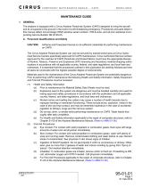
E. Airframe Zone Diagrams (See Figure 51-001), (See Figure 51-002)
To aid the repair technician in determining the structural criticality of each damage site, the following
zone diagrams identify original ply lay-up sections, composite repair zones, no-repair zones, and areas
with embedded expanded metal mesh (EMM) used in the electrical bonding of the aircraft.
CAUTION: Contact Cirrus Design before attempting to repair any composite structure within the
shaded no-repair zones. (Refer to AMM-Intro-)

CIRRUS AIRPLANE MAINTENANCE MANUAL MODEL SR20
51-00
Page 7
All
EFFECTIVITY:
Figure 51-001
Airframe Zone Diagrams Legend and Example Data
1:1 wet-lay repair plies are acceptable on engine cowling, main/nose landing gear fairings, wing tips, and wing root fairings.
NOTE
Repair plies are laid up alternately +45° and -45° from the 0° reference unless orientation is specifically defined in this section or as
a part of a Cirrus authorized field repair instruction.
The 0° reference line runs parallel to WL100 for the fuselage, perpendicular to WL100 for the wing skin, and the horizontal stabilizer
skin.
If no repair ply quantity is indicated, install twice as many plies as original lay-up.
Generally, the thickness of one ply is 0.008 - 0.010 inch (0.203 - 0.254 mm). To verify, or if no value is found in the ply lay-up tables,
determine ply count by dividing measured laminate thickness by 0.009 inch (0.229 mm).
EXTERIOR FINISH
CORE
MATERIAL
3RD INNER PLY (+45°)
2ND INNER PLY (-45°)
1ST INNER PLY (+45°)
3RD OUTER PLY (+45°)
2ND OUTER PLY (-45°)
1ST OUTER PLY (+45°)
SR20_MM51_1204E
2
TYPICAL SANDWICH CONSTRUCTION LAY-UP
PLY LAY-UP TABLE
EXTERIOR FINISH
6TH PLY (-45°)
5TH PLY (+45°)
4TH PLY (-45°)
3RD PLY (+45°)
2ND PLY (-45°)
1ST PLY (+45°)
TYPICAL SOLID LAMINATE LAY-UP
1
6
---
1
Ply Only
Quantity
Inner Ply
Quantity
Core Material
Thickness
inches (mm)
Outer Ply
Quantity
Reference
Number
-
3
0.375 (9.525)
32
Ply Only
Quantity
Inner Ply
Quantity
Core Material
Thickness
inches (mm)
Outer Ply
Quantity
Reference
Number
FS
100.0
WL 100.0
Lightning Protection
No Repair Area on
Lightning Protection
No Repair Area
LEGEND
Bond Line
It is not permissible to place repair laminations over Expanded Metal Mesh (EMM). EMM must be removed sufficiently to
accommodate the repair and replaced after the repair has been fully cured and inspected.
01 May 2012

51-00
Page 8
Serials 1005 thru 2015
EFFECTIVITY:
CIRRUS AIRPLANE MAINTENANCE MANUAL MODEL SR20
19 Sep 2010
Figure 51-002
Airframe Zone Diagrams - Serials 1005 thru 2015 (1 of 29)
45°
0°
-45°
90°
45°
0°
-45°
90°
SR20_MM51_1906C
-
-
9
-
-
4
2
-
1
2
0.250 (6.350)
0.250 (6.350)
-
0.250 (6.350)
0.375 (9.525)
4
2
-
2
2
12
11
10
9
8
Ply Only
Quantity
Inner Ply
Quantity
Core Material
Thickness
inches (mm)
Outer Ply
Quantity
Reference
Number
10
8
-
-
4
6
-
-
3
1
-
-
-
-
0.375 (9.525)
0.375 (9.525)
-
-
-
-
3
2
-
-
6
5
4
3
2
1
Ply Only
Quantity
Inner Ply
Quantity
Core Material
Thickness
inches (mm)
Outer Ply
Quantity
Reference
Number
FS
226.0
FS
296.0
FS
260.0
FS
256.0
FS 340
FS 320
FS 300
FS 280
FS 260
FS 240
FS 220
FS 200
FS 180
FS 160
FS 140
FS 120
FS 100
12
4
5
1
11
2
11
2
6
12
11
8
5
11
11
5
11
6
5
13
14
1
FS
282.5
FS
191.0
FS
202.0
FS
100.0
FS
228.0
FS
281.0
FS
235.0
8
7
5
8
9
FS
186.0
FS
202.0
FS
100.0
4
1
8
1
2
9
2
11
6
4
10
3
1
4
5
8
8
Serials 1423 thru 2015.
RIGHT SIDE VIEW FUSELAGE
12
---
7
-
4
0.250 (6.350)
4
13
-
5
0.375 (9.525)
5
14
WL 140.0
WL 130.0
WL 120.0
WL 110.0
WL 100.0
WL 90.0
WL 80.0
WL 70.0
WL 150.0
WL 160.0
Serials 1005 thru 1422.
WL 140.0
WL 130.0
WL 120.0
WL 110.0
WL 100.0
WL 90.0
WL 80.0
WL 70.0
WL 150.0
WL 160.0
Lightning Protection
No Repair Area on
Lightning Protection
LEGEND
Bond Line
No Repair Area *
Fuselage flange repair allowed per
horizontal stabilizer removal, refer to 55-10.
NOTE

CIRRUS AIRPLANE MAINTENANCE MANUAL MODEL SR20
51-00
Page 9
Serials 2016 & subs
EFFECTIVITY:
Figure 51-002
Airframe Zone Diagrams - Serials 2016 & subs (2 of 29)
45°
0°
-45°
90°
SR20_MM51_3378
-
-
9
-
-
4
2
-
1
2
0.250 (6.350)
0.250 (6.350)
-
0.250 (6.350)
0.375 (9.525)
4
2
-
2
2
12
11
10
9
8
Ply Only
Quantity
Inner Ply
Quantity
Core Material
Thickness
inches (mm)
Outer Ply
Quantity
Reference
Number
10
8
-
-
4
6
-
-
3
1
-
-
-
-
0.375 (9.525)
0.375 (9.525)
-
-
-
-
3
2
-
-
6
5
4
3
2
1
Ply Only
Quantity
Inner Ply
Quantity
Core Material
Thickness
inches (mm)
Outer Ply
Quantity
Reference
Number
FS 340
FS 320
FS 300
FS 280
FS 260
FS 240
FS 220
FS 200
FS 180
FS 160
FS 140
FS 120
FS 100
FS
228.0
FS
281.0
FS
235.0
8
7
5
8
9
FS
186.0
FS
202.0
FS
100.0
4
1
8
1
2
9
2
11
6
4
10
3
1
4
5
8
8
Serials 2016 thru 2029.
RIGHT SIDE VIEW FUSELAGE
12
---
7
-
4
0.250 (6.350)
4
13
-
5
0.375 (9.525)
5
14
WL 140.0
WL 130.0
WL 120.0
WL 110.0
WL 100.0
WL 90.0
WL 80.0
WL 70.0
WL 150.0
WL 160.0
Lightning Protection
No Repair Area on
Lightning Protection
LEGEND
Bond Line
45°
0°
-45°
90°
FS
228.0
FS
281.0
FS
235.0
8
7
5
8
9
FS
186.0
FS
202.0
FS
100.0
4
1
8
1
2
9
2
11
6
4
10
3
1
4
5
8
8
Serials 2030 & subs.
WL 140.0
WL 130.0
WL 120.0
WL 110.0
WL 100.0
WL 90.0
WL 80.0
WL 70.0
WL 150.0
WL 160.0
No Repair Area
Fuselage flange repair allowed per
horizontal stabilizer removal, refer to 55-10.
NOTE
19 Sep 2010

51-00
Page 10
Serials 1005 thru 2015
EFFECTIVITY:
CIRRUS AIRPLANE MAINTENANCE MANUAL MODEL SR20
19 Sep 2010
Figure 51-002
Airframe Zone Diagrams - Serials 1005 thru 2015 (3 of 29)
SR20_MM51_1908C
FS
224.0
FS
193.0
FS
203.0
1
2
313
3
1
3
9
10
1
6
9
6
5
1
1
FS 100
FS 120
FS 140
FS 160
FS 180
FS 200
FS 220
FS 240
FS 260
FS 280
FS 300
FS 320
FS 340
4
8
7
4
FS
100.0
FS
282.5
FS
281.0
FS
230.5
FS
202.0
FS
100.0
FS
238.0
4
3
5
3
11
5
2
1
3
3
13
1
3
2
6
12
6
9
12
Lightning Protection
No Repair Area on
Lightning Protection
LEGEND
-
-
-
-
-
1
1
4
2
4
0.250 (6.350)
0.375 (9.525)
0.250 (6.350)
0.250 (6.350)
0.375 (9.525)
2
2
4
2
4
12
11
10
9
8
Ply Only
Quantity
Inner Ply
Quantity
Core Material
Thickness
inches (mm)
Outer Ply
Quantity
Reference
Number
4
-
6
-
10
8
-
3
-
2
-
-
-
0.375 (9.525)
-
0.375 (9.525)
-
-
-
3
-
2
-
-
6
5
4
3
2
1
Ply Only
Quantity
Inner Ply
Quantity
Core Material
Thickness
inches (mm)
Outer Ply
Quantity
Reference
Number
LEFT SIDE VIEW FUSELAGE
-
5
0.375 (9.525)
57
12
---
13
WL 140.0
WL 130.0
WL 120.0
WL 110.0
WL 100.0
WL 90.0
WL 80.0
WL 70.0
WL 150.0
WL 160.0
WL 140.0
WL 130.0
WL 120.0
WL 110.0
WL 100.0
WL 90.0
WL 80.0
WL 70.0
WL 150.0
WL 160.0
Bond Line
Serials 1423 thru 2015.
Serials 1005 thru 1422.
45°
0°
-45°
90°
45°
0°
-45°
90°
No Repair Area *
Fuselage flange repair allowed per
horizontal stabilizer removal, refer to 55-10.
*NOTE

CIRRUS AIRPLANE MAINTENANCE MANUAL MODEL SR20
51-00
Page 11
Serials 2016 & subs
EFFECTIVITY:
Figure 51-002
Airframe Zone Diagrams - Serials 2016 & subs (4 of 29)
45°
0°
-45°
90°
FS
281.0
FS
230.5
FS
202.0
FS
100.0
FS
238.0
SR20_MM51_3379
FS 100
FS 120
FS 140
FS 160
FS 180
FS 200
FS 220
FS 240
FS 260
FS 280
FS 300
FS 320
FS 340
FS
281.0
FS
230.5
FS
202.0
FS
100.0
FS
238.0
4
3
5
3
11
5
2
1
3
3
13
1
3
2
6
12
6
9
12
Lightning Protection
No Repair Area on
Lightning Protection
LEGEND
-
-
-
-
-
1
1
4
2
4
0.250 (6.350)
0.375 (9.525)
0.250 (6.350)
0.250 (6.350)
0.375 (9.525)
2
2
4
2
4
12
11
10
9
8
Ply Only
Quantity
Inner Ply
Quantity
Core Material
Thickness
inches (mm)
Outer Ply
Quantity
Reference
Number
4
-
6
-
10
8
-
3
-
2
-
-
-
0.375 (9.525)
-
0.375 (9.525)
-
-
-
3
-
2
-
-
6
5
4
3
2
1
Ply Only
Quantity
Inner Ply
Quantity
Core Material
Thickness
inches (mm)
Outer Ply
Quantity
Reference
Number
LEFT SIDE VIEW FUSELAGE
-
5
0.375 (9.525)
57
12
---
13
WL 140.0
WL 130.0
WL 120.0
WL 110.0
WL 100.0
WL 90.0
WL 80.0
WL 70.0
WL 150.0
WL 160.0
Bond Line
Serials 2030 & subs.
Serials 2016 thru 2029.
45°
0°
-45°
90°
WL 140.0
WL 130.0
WL 120.0
WL 110.0
WL 100.0
WL 90.0
WL 80.0
WL 70.0
WL 150.0
WL 160.0
No Repair Area
Fuselage flange repair allowed per
horizontal stabilizer removal, refer to 55-10.
NOTE
4
3
5
3
11
5
2
1
3
3
13
1
3
2
6
12
6
9
12
19 Sep 2010

51-00
Page 12
Serials 1005 thru 2015
EFFECTIVITY:
CIRRUS AIRPLANE MAINTENANCE MANUAL MODEL SR20
19 Sep 2010
Figure 51-002
Airframe Zone Diagrams - Serials 1005 thru 2015 (5 of 29)
SR20_MM51_1910C
Lightning Protection
No Repair Area on
Lightning Protection
No Repair Area
LEGEND
-
-
-
12
4
1
2
-
0.375 (9.525)
0.250 (6.350)
0.375 (9.525)
-
4
2
2
-
11
10
9
8
7
Ply Only
Quantity
Inner Ply
Quantity
Core Material
Thickness
inches (mm)
Outer Ply
Quantity
Reference
Number
8
-
-
4
6
-
3
1
-
-
-
0.375 (9.525)
0.375 (9.525)
-
-
-
3
2
-
-
5
4
3
2
1
Ply Only
Quantity
Inner Ply
Quantity
Core Material
Thickness
inches (mm)
Outer Ply
Quantity
Reference
Number
10
---
6
-
5
0.375 (9.525)
5
BL 0.0
BL 10
BL 20
BL 30
BL 10
BL 20
BL 30
BL 0.0
BL 10
BL 20
BL 30
BL 10
BL 20
BL 30
1
8
1
8
3
3
8
1
8
1
4
4
2
9
9
Serials 1423 thru 2015.
Serials 1005 thru 1422.
FS 100
FS 120
FS 140
FS 160
FS 180
FS 200
FS 220
FS 240
FS 260
FS 280
FS 300
FS 320
FS 340
TOP VIEW FUSELAGE
5
1
4
10
4
8
8
4
11
4
1
5
45°
0°
-45°
90°
45°
0°
-45°
90°
For fuselage flange repairs at horizontal
stabilizer, refer to 53-10.
NOTE

CIRRUS AIRPLANE MAINTENANCE MANUAL MODEL SR20
51-00
Page 13
Serials 2016 & subs
EFFECTIVITY:
Figure 51-002
Airframe Zone Diagrams - Serials 2016 & subs (6 of 29)
SR20_MM51_3380
Lightning Protection
No Repair Area on
Lightning Protection
No Repair Area
LEGEND
-
-
12
1
2
-
0.250 (6.350)
0.375 (9.525)
-
2
2
-
9
8
7
Ply Only
Quantity
Inner Ply
Quantity
Core Material
Thickness
inches (mm)
Outer Ply
Quantity
Reference
Number
8
-
-
4
6
-
3
1
-
-
-
0.375 (9.525)
0.375 (9.525)
-
-
-
3
2
-
-
5
4
3
2
1
Ply Only
Quantity
Inner Ply
Quantity
Core Material
Thickness
inches (mm)
Outer Ply
Quantity
Reference
Number
10
---
6
BL 0.0
BL 10
BL 20
BL 30
BL 10
BL 20
BL 30
1
8
1
8
3
3
8
1
8
1
4
4
2
9
9
Serials 2016 thru 2029.
FS 100
FS 120
FS 140
FS 160
FS 180
FS 200
FS 220
FS 240
FS 260
FS 280
FS 300
FS 320
FS 340
TOP VIEW FUSELAGE
45°
0°
-45°
90°
For fuselage flange repairs at horizontal
stabilizer, refer to 53-10.
NOTE
1
8
1
8
3
3
8
1
8
1
4
4
2
9
9
BL 0.0
BL 10
BL 20
BL 30
BL 10
BL 20
BL 30
Serials 2030 & subs.
45°
0°
-45°
90°
19 Sep 2010

51-00
Page 14
Serials 1005 thru 2015
EFFECTIVITY:
CIRRUS AIRPLANE MAINTENANCE MANUAL MODEL SR20
19 Sep 2010
Figure 51-002
Airframe Zone Diagrams - Serials 1005 thru 2015 (7 of 29)
8
5
8
5
8
8
11
11
8
10
8
10
8
5
8
5
8
8
1
9
3
1
8
2
6
4
4
3
8
5
5
5
4
7
7
Serials 1005 thru 1422.
SR20_MM51_1912B
FS 100
FS 120
FS 140
FS 160
FS 180
FS 200
FS 220
FS 240
FS 260
FS 280
FS 300
FS 320
FS 340
Lightning Protection
No Repair Area on
Lightning Protection
No Repair Area
LEGEND
-
-
-
12
2
5
2
-
0.250 (6.350)
0.375 (9.525)
0.375 (9.525)
-
2
5
2
-
11
10
9
8
7
Ply Only
Quantity
Inner Ply
Quantity
Core Material
Thickness
inches (mm)
Outer Ply
Quantity
Reference
Number
8
-
-
4
6
-
3
1
-
-
-
0.375 (9.525)
0.375 (9.525)
-
-
-
3
2
-
-
5
4
3
2
1
Ply Only
Quantity
Inner Ply
Quantity
Core Material
Thickness
inches (mm)
Outer Ply
Quantity
Reference
Number
BOTTOM VIEW FUSELAGE
10
---
6
-
4
0.375 (9.525)
4
BL 0.0
BL 10
BL 20
BL 30
BL 10
BL 20
BL 30
BL 0.0
BL 10
BL 20
BL 30
BL 10
BL 20
BL 30
Bond Line
Serials 1423 thru 2015.
45°
0°
-45°
90°
45°
0°
-45°
90°

CIRRUS AIRPLANE MAINTENANCE MANUAL MODEL SR20
51-00
Page 15
Serials 2016 & subs
EFFECTIVITY:
Figure 51-002
Airframe Zone Diagrams - Serials 2016 & subs (8 of 29)
8
8
3
3
8
8
8
8
1
3
1
8
2
6
4
4
3
8
5
4
7
7
SR20_MM51_3381
FS 100
FS 120
FS 140
FS 160
FS 180
FS 200
FS 220
FS 240
FS 260
FS 280
FS 300
FS 320
FS 340
Lightning Protection
No Repair Area on
Lightning Protection
No Repair Area
LEGEND
-
12
2
-
0.375 (9.525)
-
2
-
8
7
Ply Only
Quantity
Inner Ply
Quantity
Core Material
Thickness
inches (mm)
Outer Ply
Quantity
Reference
Number
8
-
-
4
6
-
3
1
-
- -
0.375 (9.525)
0.375 (9.525)
-
- -
3
2
-
-
5
4
3
2
1
Ply Only
Quantity
Inner Ply
Quantity
Core Material
Thickness
inches (mm)
Outer Ply
Quantity
Reference
Number
BOTTOM VIEW FUSELAGE
10
---
6
BL 0.0
BL 10
BL 20
BL 30
BL 10
BL 20
BL 30
Bond Line
Serials 2016 thru 2029.
45°
0°
-45°
90°
5
5
5
5
5
5
5
5
8
8
7
7
5
4
8
8
45°
0°
-45°
90°
1
BL 0.0
BL 10
BL 20
BL 30
BL 10
BL 20
BL 30
Serials 2030 & subs.
1
2
6
4
4
19 Sep 2010

51-00
Page 16
Serials 1005 thru 1885
EFFECTIVITY:
CIRRUS AIRPLANE MAINTENANCE MANUAL MODEL SR20
19 Sep 2010
Figure 51-002
Airframe Zone Diagrams - Serials 1005 thru 1885 (9 of 29)
Serials 1005 thru 1877, 1879 thru 1885.
SR20_MM51_2128B
9
10
2
7
4
6
---
1
Ply Only
Quantity
Inner Ply
Quantity
Core Material
Thickness
inches (mm)
Outer Ply
Quantity
Reference
Number
4
---
2
4
---
3
Repair Plies
To Original
Lay-Up
-
2
0.375 (9.525)
24
Ply Only
Quantity
Inner Ply
Quantity
Core Material
Thickness
inches (mm)
Outer Ply
Quantity
Reference
Number
5
Repair Plies
To Original
Lay-Up
9
---
1.5 to 1.0
1.5 to 1.0
2.0 to 1.0
2.0 to 1.0
2.5 to 1.0
LEFT WING TOP VIEW SHOWN
RIGHT WING TOP OPPOSITE
5
8
WS
20
WS
40
WS
60
WS
80
WS
100
WS
120
WS
140
WS
160
WS
180
WS
200
3
1
8
6
45°
0°
-45°
90°
Bond Line
LEFT WING CUFF TOP VIEW SHOWN
RIGHT WING CUFF TOP OPPOSITE
WS
200
WS
180
WS
160
WS
140
WS
120
45°
0°
-45°
90°
11
3
WING SKIN
(REF)
68
---
3.0 to 1.0
6
---
7
6
---
8
-
4
0.375 (9.525)
49
-
2
0.375 (9.525)
4
10
11
8
---
1.0 to 1.0
2.0 to 1.0
2.0 to 1.0
2.5 to 1.0
2.0 to 1.0
No Repair Area on
Lightning Protection
No Repair Area
Lightning Protection
LEGEND

CIRRUS AIRPLANE MAINTENANCE MANUAL MODEL SR20
51-00
Page 17
Serials 1005 thru 1885
EFFECTIVITY:
Figure 51-002
Airframe Zone Diagrams - Serials 1005 thru 1885 (10 of 29)
SR20_MM51_1209D
Ply Only
Quantity
Inner Ply
Quantity
Core Material
Thickness
inches (mm)
Outer Ply
Quantity
Reference
Number
4
---
1
4
---
2
-
2
0.375 (9.525)
23
-
3
0.375 (9.525)
24
Repair Plies
To Original
Lay-Up
-
2
0.375 (9.525)
2
8
7
Ply Only
Quantity
Inner Ply
Quantity
Core Material
Thickness
inches (mm)
Outer Ply
Quantity
Reference
Number
8
---
9
11
Repair Plies
To Original
Lay-Up
5
---
5
6
---
12
-
1
0.250 (6.350)
2
-
2
0.250 (6.350)
28
---
6
1.5 to 1.0
2.0 to 1.0
1.5 to 1.0
2.0 to 1.0
2.0 to 1.0
2.5 to 1.0
2.0 to 1.0
1.5 to 1.0
2.0 to 1.0
2.0 to 1.0
2.0 to 1.0
LEFT WING BOTTOM VIEW SHOWN
RIGHT WING BOTTOM OPPOSITE
WS
20
WS
40
WS
60
WS
80
WS
100
WS
120
WS
140
WS
160
WS
180
WS
200
3
4
6
7
5
2
8
1
Lightning Protection
Bond Line
LEGEND
WING SKIN
(REF)
12
11
10
2
9
90°
-45°
0°
45°
9
LEFT WING CUFF BOTTOM VIEW SHOWN
RIGHT WING CUFF BOTTOM OPPOSITE
45°
0°
-45°
90°
WS
200
WS
180
WS
160
WS
140
WS
120
10
8
---
2.0 to 1.0
5
7
2
Serials 1005 thru 1877, 1879 thru 1885.
19 Sep 2010

51-00
Page 18
Serials 1886 & subs
EFFECTIVITY:
CIRRUS AIRPLANE MAINTENANCE MANUAL MODEL SR20
19 Sep 2010
Figure 51-002
Airframe Zone Diagrams - Serials 1886 & subs (11 of 29)
-
3
1.5 to 1.0
8
0.375 (9.525)
4
14
2
1.5 to 1.0
---
-
4
2.0 to 1.0
4
0.375 (9.525)
4
-
5
2.0 to 1.0
6
0.335 (8.509)
6
76
1.5 to 1.0
---
-
7
2.0 to 1.0
2
0.375 (9.525)
4
-
8
1.5 to 1.0
1
0.375 (9.525)
4
3
---
10
1.5 to 1.0
-
1
0.375 (9.525)
2
11
2.0 to 1.0
-
2
0.375 (9.525)
2
12
2.0 to 1.0
4
---
13
2.0 to 1.0
6
---
14
2.0 to 1.0
8
---
15
2.0 to 1.0
-
1
0.125 (3.175)
2
16
1.5 to 1.0
-
3
0.375 (9.525)
2
17
1.5 to 1.0
6
17
10
12
11
12
11
13
15
13
6
13
16
12
11
4
9
8
3
10
15
10
11
7
15
1
2
15
14
4
5
LEFT WING TOP VIEW SHOWN
RIGHT WING TOP OPPOSITE
Lightning Protection
Bond Line
No Repair Area on
Lightning Protection
No Repair Area
LEGEND
SR20_MM51_2738A
Lightning Protection
Bond Line
No Repair Area on
Lightning Protection
No Repair Area
LEGEND
Serials 1878, 1886 & subs.
WS
20
WS
40
WS
60
WS
80
WS
120
WS
100
WS
140
WS
160
WS
180
WS
200
WS
220
12
1
Ply Only
Quantity
Inner Ply
Quantity
Core Material
Thickness
inches (mm)
Outer Ply
Quantity
Reference
Number
5
---
9
Repair Plies
To Original
Lay-Up
Ply Only
Quantity
Inner Ply
Quantity
Core Material
Thickness
inches (mm)
Outer Ply
Quantity
Reference
Number
Repair Plies
To Original
Lay-Up
1.5 to 1.0 1.5 to 1.0
---
45°
0°
-45°
90°

CIRRUS AIRPLANE MAINTENANCE MANUAL MODEL SR20
51-00
Page 19
Serials 1886 & subs
EFFECTIVITY:
Figure 51-002
Airframe Zone Diagrams - Serials 1886 & subs (12 of 29)
83
2.0 to 1.0
---
-
2
2.0 to 1.0
5
0.375 (9.525)
3
64
1.5 to 1.0
---
45
1.5 to 1.0
---
-
6
1.5 to 1.0
3
0.375 (9.525)
3
37
1.0 to 1.0
---
-
8
2.0 to 1.0
-
0.375 (9.525)
2
12
1
2.0 to 1.0
---
-
1
0.375 (9.525)
2
10
1.5 to 1.0
9
---
11
1.0 to 1.0
-
3
0.375 (9.525)
2
12
2.0 to 1.0
5
---
13
2.0 to 1.0
-
2
0.225 (5.715)
29
2.0 to 1.0
Ply Only
Quantity
Inner Ply
Quantity
Core Material
Thickness
inches (mm)
Outer Ply
Quantity
Reference
Number
Repair Plies
To Original
Lay-Up
Ply Only
Quantity
Inner Ply
Quantity
Core Material
Thickness
inches (mm)
Outer Ply
Quantity
Reference
Number
Repair Plies
To Original
Lay-Up
Lightning Protection
Bond Line
No Repair Area on
Lightning Protection
No Repair Area
LEGEND
Serials 1878, 1886 & subs.
3
9
8
8
8
7
9
4
3
5
8
5
13
3
8
5
4
3
8
3
7
10
8
5
4
11
3
4
5
6
5
13
1
4
2
1
3
7
6
3
6
12
WS
220
WS
200
WS
180
WS
160
WS
120
WS
140
WS
100
WS
80
WS
60
WS
40
WS
20
LEFT WING BOTTOM VIEW
SR20_MM51_2739
45°
0°
-45°
90°
19 Sep 2010

51-00
Page 20
Serials 1886 & subs
EFFECTIVITY:
CIRRUS AIRPLANE MAINTENANCE MANUAL MODEL SR20
19 Sep 2010
Figure 51-002
Airframe Zone Diagrams - Serials 1886 & subs (13 of 29)
83
2.0 to 1.0
---
-
2
2.0 to 1.0
5
0.375 (9.525)
3
64
1.5 to 1.0
---
45
1.5 to 1.0
---
-
6
1.5 to 1.0
3
0.375 (9.525)
3
37
1.0 to 1.0
---
-
8
2.0 to 1.0
2
0.375 (9.525)
2
12
1
2.0 to 1.0
---
-
1
0.375 (9.525)
2
10
1.5 to 1.0
9
---
11
1.0 to 1.0
-
3
0.375 (9.525)
2
12
2.0 to 1.0
5
---
13
2.0 to 1.0
-
2
0.225 (5.715)
29
2.0 to 1.0
Lightning Protection
Bond Line
No Repair Area on
Lightning Protection
No Repair Area
LEGEND
Lightning Protection
Bond Line
No Repair Area on
Lightning Protection
No Repair Area
LEGEND
Serials 1878, 1886 & subs.
Ply Only
Quantity
Inner Ply
Quantity
Core Material
Thickness
inches (mm)
Outer Ply
Quantity
Reference
Number
Repair Plies
To Original
Lay-Up
Ply Only
Quantity
Inner Ply
Quantity
Core Material
Thickness
inches (mm)
Outer Ply
Quantity
Reference
Number
Repair Plies
To Original
Lay-Up
3
7
8
9
8
7
8
3
5
4
9
5
8
4
5
8
3
3
5
10
8
8
4
11
3
1
4
4
5
6
13
5
8
2
1
3
7
6
13
3
12
63
RIGHT WING BOTTOM VIEW
SR20_MM51_2740A
45°
0°
-45°
90°
WS
20
WS
40
WS
60
WS
80
WS
120
WS
100
WS
140
WS
160
WS
180
WS
200
WS
220
/