Page is loading ...

CIRRUS AIRPLANE MAINTENANCE MANUAL MODEL SR20
32-42
Page 1
All
EFFECTIVITY:
BRAKES
1. DESCRIPTION
The brake system consists of single disc brake assembly on each main landing gear wheel, master cylin-
der for each rudder pedal, hydraulic fluid reservoir, parking brake, and associated hydraulic plumbing.
Serials 1593 & subs, 1005 thru 1592 after SB2X-32-14: A brake temperature indicator is installed on each
brake caliper piston housing. The indicator turns black if overheating occurs.
Serials 2016 & subs w/ Perspective Avionics: A brake temperature sensor is installed on each brake
assembly. Brake temperature annunciations are displayed on the MFD. A caution annunciation occurs
when brake temperature is between 270°F (132°C) and 293° F (145°C). A warning annunciation occurs
when brake temperature exceeds 293°F (145°C). 28 VDC is supplied through the ENG INST circuit
breaker on the Main Bus 2.
The hydraulically operated brakes are individually activated by floor mounted toe pedals located at both
pilot stations. The master cylinders are located forward of the pilot’s rudder pedals. The hydraulic fluid res-
ervoir is located in the engine compartment on the upper RH side of the firewall.
Serials 1005 thru 2240 before SB2X-32-21: The reservoir is serviced with MIL-H-5606 hydraulic fluid.
Serials 1005 thru 2240 after SB2X-32-21, 2241 & subs: The reservoir is serviced with MIL-PRF-87257
hydraulic fluid.
For disassembly/assembly of brake master cylinder refer to the manufacturer’s approved Instructions For
Continued Airworthiness.
A parking brake mechanism holds induced hydraulic pressure on the disc brakes for parking. The parking
brake system consists of a parking brake valve, control cable with knob, and associated hydraulic plumb-
ing. The parking brake valve is mounted adjacent to the firewall on the LH side of the outboard console rib.
Serials 1005 thru 2015, 2016 & subs w/o Perspective Avionics: The parking brake control cable knob is
mounted to the LH side of the mid console, adjacent to the alternate air controls.
Serials 2016 & subs w/ Perspective Avionics: The parking brake control cable handle is mounted to the LH
kick plate. A position sensor, mounted adjacent to the parking brake valve actuation arm, sends position
data to the MFD via the GEA 71 engine airframe unit. An alert indicates in the CAS window of the MFD
when the parking brake is engaged.
15 Dec 2014

32-42
Page 2
All
EFFECTIVITY:
CIRRUS AIRPLANE MAINTENANCE MANUAL MODEL SR20
15 Dec 2014
2. TROUBLESHOOTING
Trouble Probable Cause Remedy
Brake drag. Piston cocked in cylinder,
resulting in overheating brake
and/or excessive lining wear.
Remove and repair cylinder or pis-
ton. Replace brake assembly.
(Refer to 32-42)
Foreign matter wedged in brakes. Locate and remove foreign matter.
Back pressure due to
malfunction of master cylinder.
Perform Adjustment/Test - Bleed-
ing the Brake System. (Refer to
32-42)
Repair or replace master cylinder.
(Refer to 32-42)
Back pressure due to
malfunction of parking brake
valve.
Perform Adjustment/Test - Bleed-
ing the Brake System. (Refer to
32-42)
Replace parking brake valve.
(Refer to 32-42)
Wrong brake fluid has caused
blocking of pistons.
Change all seals of the brake sys-
tem. Use correct brake fluid.
(Refer to 12-10)
Water or ice in hydraulic system. Thaw ice and flush system. Per-
form Adjustment/Test - Bleeding
the Brake System. (Refer to 32-
42)
Excessive bolt torque has caused
back plate to crush
cylinder, evidenced by
depressions around bolt holes.
Replace cylinder and follow
manufacturer's recommended
torque value.
Piston does not retract. Perform Adjustment/Test - Bleed-
ing the Brake System. (Refer to
32-42)
Remove piston and inspect for
damage. (Refer to 32-42)
Warped pressure plate. Replace pressure plate or flatten
to within 0.100 inch (0.254 mm).
(Refer to 32-42)
Corroded anchor bolts and/or
torque plate bushings.
Clean and lubricate or replace.
Cocked anchor bolts and/or torque
plate bushings.
Replace anchor bolts and/or
torque plate bushings. (Refer to
32-42)
Bent or cracked torque plate. Replace torque plate. (Refer to 32-
42)
Restriction in hydraulic line. Isolate and remove restriction.

CIRRUS AIRPLANE MAINTENANCE MANUAL MODEL SR20
32-42
Page 3
All
EFFECTIVITY:
Brake drag. (continued) Lining out of position or stuck. Repair or replace lining.
(Refer to 32-42)
Warped brake disk/disc. Inspect brake disk/disc by laying a
straightedge across brake disk
face. Replace brake disk/disc.
(Refer to 32-42)
Lining not seated flush against
pressure plate or back plate.
Deburr rivet hole on surface adja-
cent to lining.
Parking brake control cable stop
incorrectly adjusted.
Perform Inspection/Check - Park-
ing Brake Control Cable. (Refer to
32-42)
Brakes inoperative. Brake fluid level low. Replenish brake fluid. (Refer to
12-10)
Air in brake system. Perform Adjustment/Test - Bleed-
ing the Brake System. (Refer to
32-42)
Defective master cylinder. Replace master cylinder.
(Refer to 32-42)
Defective caliper. Replace caliper. (Refer to 32-42)
Worn brake linings. Perform Inspection/Check - Brake
Temperature Indicator. (Refer to
32-42)
Replace O-rings. (Refer to 32-42)
Replace brake linings. (Refer to
32-42)
Leaky brake line connections Tighten or replace connectors.
Parking brake inoperative. Parking brake valve defective. Replace parking brake valve.
(Refer to 32-42)
Parking brake will not release. Control cable stop incorrectly
adjusted.
Perform Inspection/Check - Park-
ing Brake Control Cable. (Refer to
32-42)
Defective control cable. Replace control cable. (Refer to
32-42)
Brake overheating. Improper and/or aggressive brak-
ing practices.
Perform Inspection/Check - Brake
Temperature Indicator. (Refer to
32-42)
Replace O-rings. (Refer to 32-42)
Replace brake linings. (Refer to
32-42)
Trouble Probable Cause Remedy
15 Dec 2014

32-42
Page 4
All
EFFECTIVITY:
CIRRUS AIRPLANE MAINTENANCE MANUAL MODEL SR20
15 Dec 2014
Rapid brake disk/disc and lining
wear.
Improper adjustment of master
cylinder rod length restricting the
development of maximum stroke.
Adjust cylinder rod length.
(Refer to 32-42)
Improper conditioning of brake lin-
ings.
Perform Adjustment/Test - Condi-
tioning Procedure for Brake Lin-
ings.
(Refer to 32-42)
Excessive rusting, scoring, or
pitting of brake disk/disc.
Clean or replace brake disk/disc.
Excessive back plate deflection
caused by bent bolts or over
torquing bolts.
Replace bolts. Torque bolts to
proper value.
Unable to obtain sufficient hydrau-
lic brake pressure, excessive toe
pedal travel, or spongy pedal.
Air in hydraulic system. Perform Adjustment/Test - Bleed-
ing the Brake System. (Refer to
32-42)
Vent in master cylinder reservoir
clogged.
Clean vent or overboard drain.
Leak in hydraulic system. Locate leak and repair.
Defective master cylinder. Replace or repair master cylinder.
(Refer to 32-42)
Back plate bolts loose or not prop-
erly torqued, causing
excessive brake deflection.
Torque bolts to proper value.
Excess bolt torque has caused
back plate to crush cylinder,
evidenced by depressions around
bolt holes.
Replace cylinder.
Defective brake line (ballooning). Replace brake line.
Trouble Probable Cause Remedy

CIRRUS AIRPLANE MAINTENANCE MANUAL MODEL SR20
32-42
Page 5
All
EFFECTIVITY:
Brakes won't hold. Contaminated brake lining. Replace brake lining. (Refer to 32-
42)
Improper conditioning of brake lin-
ings.
Perform Adjustment/Test - Condi-
tioning Procedure for Brake Lin-
ings.
(Refer to 32-42)
Wrong brake fluid has caused
blocking of pistons.
Change all seals of the brake sys-
tem. Use correct brake fluid.
(Refer to 12-10)
Brake linings worn below
minimum wear limits.
Perform Inspection/Check - Brake
Linings. (Refer to 32-42)
Brake disk/disc worn below mini-
mum wear limits.
Refer to the manufacturer’s
approved Instructions For Contin-
ued Airworthiness.
Brake lining carbonized
(overheated).
Perform Inspection/Check - Brake
Temperature Indicator. (Refer to
32-42)
Replace brake lining. (Refer to 32-
42)
Pressure plate contacting torque
plate assembly.
Check for correct torque plate and
wheel installation.
New brake linings not seated in
wear track of old brake disk/disc,
resulting in partial contact with
brake disk/disc.
Refer to the manufacturer’s
approved Instructions For Contin-
ued Airworthiness.
Brake fluid leaking. O-rings damaged. Replace O-rings. (Refer to 32-42)
Connections or hoses leaking. Locate leak and repair.
Cylinder scored/deteriorated or
obstructed by debris.
Clean cylinder.
Replace cylinder.
Trouble Probable Cause Remedy
15 Dec 2014

32-42
Page 6
All
EFFECTIVITY:
CIRRUS AIRPLANE MAINTENANCE MANUAL MODEL SR20
15 Dec 2014
3. MAINTENANCE PRACTICES
A. Brake System Replenishing (Refer to 12-10)
B. Brake Assembly - Serials 1005 thru 2240 before SB2X-32-21 (See Figure 32-421)
(1) Removal - Brake Assembly
WARNING:
Verify parking brake is in off position and wheels are blocked.
(a) Remove main gear fairings. (Refer to 32-10)
(b) Remove and cap hydraulic line attached to brake. Cap brake inlet fitting.
(c) Serials 1005 thru 1600 before SB2X-32-13: Remove bolts and washers securing back
plate to cylinder assembly. Remove back plate.
(d) Serials 1601 thru 2015, 2016 & subs w/o Perspective Avionics, 1005 thru 1600 after
SB2X-32-13: Remove bolts and washers securing back plate and shim to cylinder assem-
bly. Remove back plate and shim.
(e) Serials 2016 & subs w/ Perspective Avionics: Remove bolts and washers securing back
plate, shim, and temperature sensor to cylinder assembly. Remove back plate, shim, and
temperature sensor.
(f) Carefully slide anchor bolts secured to cylinder assembly off torque plate.
(g) If torque plate removal is required:
1
Remove wheel/tire. (Refer to 32-41)
2
Remove bolts, nuts, and washers securing torque plate to axle flange. Remove
torque plate.
(2) Disassembly - Brake Assembly
(a) Slide pressure plate over and off anchor bolts secured to cylinder assembly.
(b) Remove piston(s) by injecting air into ports (15-20 psi) [103 to 138 kPa] maximum pres-
sure.
CAUTION: Care should be used in handling O-ring(s) to prevent damage.
(c) Remove O-ring(s) from piston(s).
(d) Serials 1601 thru 2240, 1005 thru 1600 after SB2X-32-13: Remove friction springs from
pistons.
(e) Remove bleeder seat, screw, cap, and inlet fitting.
(f) Remove anchor bolts secured to cylinder assembly, if necessary.
(g) Remove brake linings, if necessary. (Refer to 32-42)
(h) Serials 1593 thru 2240, 1005 thru 1592 after SB2X-32-14: Remove brake temperature
indicator. (Refer to 32-42)
(3) Reassembly - Brake Assembly
Note: Thoroughly clean parts before assembling.
(a) Acquire necessary tools, equipment, and supplies.
Description P/N or Spec. Supplier Purpose
Arbor Press - Any Source Install anchor
bolts.

CIRRUS AIRPLANE MAINTENANCE MANUAL MODEL SR20
32-42
Page 7
All
EFFECTIVITY:
(b) If removed, install brake lining. (Refer to 32-42)
(c) If anchor bolts were removed, install anchor bolts using arbor press and a holding fixture.
Install washers and nuts. Torque nuts to 90 in-lb (10 Nm).
(d) Install inlet fitting and torque to 40 - 50 in-lb (4.5 - 5.6 Nm).
Note: Cap fittings if brake is not being immediately installed on the airplane.
(e) Install bleeder seat, screw, and cap. Torque to 40 - 50 in-lb (4.5 - 5.6 Nm).
(f) Serials 1601 thru 2240, 1005 thru 1600 after SB2X-32-13: Install friction springs on pis-
tons.
(g) Install O-ring(s) on piston(s) and lubricate.
(h) Place piston(s) in cylinder bore(s) and verify piston(s) and O-ring(s) are in proper align-
ment
(i) Press piston(s) into cylinder bore(s) by hand. If required, tap the piston(s) squarely with a
wooden or plastic mallet while rotating piston(s).
CAUTION: Care should be exercised to prevent over tightening the inlet fitting which
could result in cracking of cylinder casting. Finger tighten the inlet fitting,
rotate one to two turns to obtain proper installation orientation, and torque to
specified value.
(j) Install pressure plate lining facing away from piston(s) by sliding over anchor bolts. Verify
pressure plate slides freely over anchor bolts.
(k) Serials 1593 thru 2240, 1005 thru 1592 after SB2X-32-14: Install brake temperature indi-
cator. (Refer to 32-42)
(4) Installation - Brake Assembly
(a) Acquire necessary tools, equipment, and supplies.
(b) If torque plate installation is required:
1
Orient and install torque plate on axle flange with bolts, nuts, and washers. Torque
to 160 - 190 in-lb (18 - 21 Nm).
2
Install wheel assembly. (Refer to 32-41)
Note: Dry film lubricants such as silicone spray should be applied to anchor bolts
and torque plate bushings to assist sliding motion. Exercise care to verify
that linings do not become contaminated with fluid or lubricant. For best ser-
vice life, cylinders must slide freely in torque plate.
O-Ring Lubricant Dow Corning
55 O-Ring
Lubricant
Dow Chemical Co.
Midland, Michigan 48674
989-636-1000
Lubrication.
Silicon Spray - Any Source Lubrication.
Mallet (plastic or wooden) - Any Source Piston installation.
Description P/N or Spec. Supplier Purpose
Silicon Spray - Any Source Lubrication.
Description P/N or Spec. Supplier Purpose
15 Dec 2014

32-42
Page 8
All
EFFECTIVITY:
CIRRUS AIRPLANE MAINTENANCE MANUAL MODEL SR20
15 Dec 2014
(c) Carefully slide anchor bolts secured to cylinder assembly into torque plate bushings.
(d) Position back plate(s) between brake disk and wheel.
(e) Serials 1005 thru 1600 before SB2X-32-13: Install bolts and washers securing back plates
to cylinder assembly. Torque to 75 - 80 in-lb (8.5 - 9.1 Nm).
(f) Serials 1601 thru 2015, 2016 & subs w/o Perspective Avionics, 1005 thru 1600 after SB
2X-32-13: Install bolts and washers securing back plates and shim to cylinder assembly.
Torque to 90 in-lb (10.2 Nm).
(g) Serials 2016 & subs w/ Perspective Avionics: Install bolts and washers securing back
plates, shim, and temperature sensor to cylinder assembly. Torque to 90 in-lb (10.2 Nm).
(h) Uncap and attach hydraulic line to cylinder inlet fitting.
(i) Bleed the system. (Refer to 32-42)
(j) Install main gear fairings. (Refer to 32-10)
(k) Perform Adjustment/Test - Conditioning Procedure for Brake Linings. (Refer to 32-42)
(5) Inspection/Check - Brake Assembly
(a) Serials 1005 thru 2030 before SB2X-05-01: Inspect brake assembly.
1
Disassemble brake assembly. (Refer to 32-42)
2
Perform Inspection/Check - Brake Linings. (Refer to 32-42)
3
Inspect brake cylinder bores for evidence of scoring and deterioration. If scored,
replace brake caliper assembly.
4
Using new O-rings, reassemble brake assembly. (Refer to 32-42)
(b) Serials 2031 thru 2240, 1005 thru 2030 after SB2X-05-01: Inspect brake assembly.
1
Perform Inspection/Check - Brake Linings. (Refer to 32-42)
2
Perform Inspection/Check - Brake Temperature Indicator. (Refer to 32-42)

CIRRUS AIRPLANE MAINTENANCE MANUAL MODEL SR20
32-42
Page 9
Serials 1005 thru 2240 after SB2X-32-21, 2241 & subs
EFFECTIVITY:
C. Brake Assembly - Serials 1005 thru 2240 after SB2X-32-21, 2241 & subs (See Figure 32-421)
(1) Removal - Brake Assembly
CAUTION: Verify parking brake is in off position and wheels are blocked.
(a) Remove main gear fairings. (Refer to 32-10)
(b) Raise airplane on jacks. (Refer to 07-10)
(c) Remove cotter pin from axle and remove axle nut. (Refer to 32-41)
(d) Cut and remove safety wire around brake disc.
(e) Remove wheel/tire. (Refer to 32-41)
(f) Serials w/ Perspective Avionics: Remove brake temperature sensor. (Refer to 32-42)
(g) Remove inlet fitting, washers, and hydraulic line from brake cylinder. Cap hydraulic line
and inlet on brake cylinder.
(h) Remove bolts and washers securing brake assembly to axle.
(2) Disassembly - Brake Assembly
(a) Acquire necessary tools, equipment, and supplies.
(b) Remove screws securing back plate to brake cylinder.
(c) Separate cylinder, brake pads, brake disc, and back plate.
WARNING:
Pistons will be ejected at high velocities.
CAUTION: Care should be used in handling O-rings to prevent damage.
Do not use metal tools to remove O-rings from pistons. Metal tools will
scratch the seal groove and cause fluid leakage.
Note: Air pressure can be used to remove pistons. Replace caliper back plate and
blow air pressure into inlet on brake cylinder.
(d) Remove O-rings from pistons with a plastic dental pick.
(e) Remove bleeder screw from brake cylinder.
(f) Remove cotter pins securing back stops to brake pads. Remove back stops.
(g) Clean brake assembly.
WARNING:
Dry cleaning solvents are toxic and volatile. Use a well-ventilated
room and avoid contact with skin and clothing. Do not inhale vapor.
Description P/N or Spec. Supplier Purpose
Plastic Dental Pick - Any Source Remove O-rings.
Compressed Air Supply - Any Source Facilitate piston
removal and clean-
ing.
Dry Cleaning Solvent - Any Source Clean seal
grooves.
Cotton Cloth
(clean and lint free)
- Any Source Clean parts.
15 Dec 2014

32-42
Page 10
Serials 1005 thru 2240 after SB2X-32-21, 2241 & subs
EFFECTIVITY:
CIRRUS AIRPLANE MAINTENANCE MANUAL MODEL SR20
15 Dec 2014
CAUTION: Do not use basic or acidic cleaning agents on wheel halves. Anodizing can
be removed if exposed to basic agents. Do not damage ball bearing seal or
expose to solvents.
1
Clean all metal parts using water with soap and wipe dry with a clean cloth.
CAUTION: Use dry cleaning solvent only on seal grooves.
2
Clean seal grooves with a soft plastic brush and dry-cleaning solvent.
CAUTION: Do not use oily solvent or oily air pressure on internal threads
because threadlocker will not properly lock screws if exposed to oil.
Ensure that no dust remains inside seal grooves.
3
Apply air pressure to dry internal threads and seal grooves.
(h) Remove brake temperature indicator. (Refer to 32-42)
(3) Reassembly - Brake Assembly
Note: Thoroughly clean parts before assembling.
(a) Acquire necessary tools, equipment, and supplies.
(b) Perform Inspection/Check - Brake Assembly. (Refer to 32-42)
CAUTION: Do not use silicone spray (liquid) in place of thick silicone grease where
specified.
Do not use tools to manually insert seals or pistons into cylinder bores.
Never re-use a piston seal that has been removed from a cylinder bore
groove.
(c) Lubricate new seals with a thin coat of thick silicone grease.
(d) Lubricate cylinder bores with a thin coat of thick silicone grease.
(e) Insert seals into cylinder bore grooves by hand only.
(f) Lubricate piston cylinder with a thin coat of thick silicone grease.
(g) Insert pistons into cylinder bores by hand only.
(h) Verify pistons and O-rings are in proper alignment.
Description P/N or Spec. Supplier Purpose
O-Ring Lubricant Dow Corning
55 O-Ring
Lubricant
Dow Chemical Co.
Midland, Michigan 48674
989-636-1000
Lubrication.
Silicone Grease, Thick
(-50°C to 200°C)
Compliant w/
FDA CFR
178.3570
Any Source Lubrication.
Loctite® Threadlocker,
Medium
242 or 243 Any Source Secure screws.

CIRRUS AIRPLANE MAINTENANCE MANUAL MODEL SR20
32-42
Page 11
Serials 1005 thru 2240 after SB2X-32-21, 2241 & subs
EFFECTIVITY:
CAUTION: If piston does not slide into cylinder bores with pressure of only one or two
fingers, it is sticking which can lead to brake damage and overheating. Do
not attempt to sand or polish pistons. If pistons are sticking, they must be
replaced.
Copper seals must be changed at each removal of the hydraulic fitting.
(i) Insert new bleeder screw and change copper seals.
(j) Using thick silicone grease, lubricate contact area between back stops and back plate.
(k) Insert new cotter pins to secure back stops.
(l) Install new brake pads.
(m) Apply medium threadlocker to new screws used to secure back plate to cylinder.
(n) Install screws securing brake pads in place. Torque to 220 in-lb (25 Nm).
(o) Re-torque all screws to 220 in-lb (25 Nm).
(p) Ensure brake pads slide without effort.
(q) Position brake disc between brake pads.
(r) Install brake temperature indicator. (Refer to 32-42)
(4) Installation - Brake Assembly
(a) Acquire necessary tools, equipment, and supplies.
(b) Orient and install brake assembly on axle flange with bolts, nuts, and washers. Torque to
350 in-lb (39.5 Nm).
(c) Position wheel/tire onto axle while placing brake disc into wheel slots.
(d) Install wheel/tire. (Refer to 32-41)
(e) Install safety wire securing brake disc to wheel. (Refer to 20-50)
(f) Uncap hydraulic line and inlet on brake cylinder.
(g) Install washers, hydraulic line, and inlet fitting to brake cylinder. Torque to 220 in-lb (24.86
Nm).
(h) Serials w/ Perspective Avionics: Install brake temperature sensor. (Refer to 32-42)
(i) Bleed the system. (Refer to 32-42)
(j) Remove jacks and lower airplane. (Refer to 07-10)
(k) Install main gear fairings. (Refer to 32-10)
Description P/N or Spec. Supplier Purpose
Safety Wire, Stainless
Steel
0.041”
diameter wire
(grade 302)
Any Source Safetying brake
disc to wheel.
15 Dec 2014

32-42
Page 12
Serials 1005 thru 2240 after SB2X-32-21, 2241 & subs
EFFECTIVITY:
CIRRUS AIRPLANE MAINTENANCE MANUAL MODEL SR20
15 Dec 2014
(5) Inspection/Check - Brake Assembly
(a) Visually inspect brake cylinder and back plate for cracks, nicks, corrosion, or other dam-
age.
(b) Ensure none of the following conditions exist.
CAUTION: If damage is identified during inspection, brake cylinder and/or back plate
must be replaced.
1
Signs of deep corrosion,
2
Anodizing color removed on more than 15% of external surface,
3
Heavy nicks,
4
Anodizing removed on internal piston bore,
5
Scratched piston bore, and
6
Scratched or damaged seal groove.
CAUTION: Anodizing coating must not be painted.
Do not use sandpaper on any parts. Sandpaper will remove anodizing coat-
ing.
Do not try to sand or polish internal piston bore, it will remove anodizing
coating.
(c) Verify brake disc wear limits are not exceeded. Refer to the manufacturer’s approved
Instructions For Continued Airworthiness for more information.
(d) Perform Inspection/Check - Brake Pads. (Refer to 32-42)
(e) Perform Inspection/Check - Brake Temperature Indicator. (Refer to 32-42)

CIRRUS AIRPLANE MAINTENANCE MANUAL MODEL SR20
32-42
Page 13
Serials 1005 thru 2240 before SB2X-32-21
EFFECTIVITY:
D. Brake Linings - Serials 1005 thru 2240 before SB2X-32-21 (See Figure 32-421)
(1) Removal - Brake Linings
(a) Acquire necessary tools, equipment, and supplies.
(b) Remove brake assembly. (Refer to 32-42)
(c) Slide pressure plate over and off anchor pins secured to cylinder assembly.
(d) Serials 1005 thru 1600 before SB2X-32-13: Remove rivets.
CAUTION: Do not damage pressure plate during rivet removal.
1
Using 1/8-inch drill bit, remove rivets attaching lining to pressure plate.
2
Using 1/8-inch drill bit, remove rivets attaching lining to back plates.
(e) Separate linings from pressure plate and back plates.
(f) Clean pressure plate and back plate surfaces of dirt and grease.
(2) Installation - Brake Linings
(a) Acquire necessary tools, equipment, and supplies.
(b) Inspect pressure plate and back plate(s) for excessive corrosion, visible damage, or
excessive warping.
Note: Pressure plates should not be used if warped in excess of 0.010 inch (0.254
mm) flatness. Excessive warping can result in brake drag especially when
new disk and linings are installed.
(c) Align new lining on pressure plate and back plates.
(d) Serials 1005 thru 1600 before SB2X-32-13: Install rivets.
1
Using arbor press, secure lining to pressure plate.
2
Using arbor press, secure lining to back plates.
3
Verify linings are tight and movement free with no distortion of parts.
(e) Clean dirt, grease, etc. from cylinder, pressure plate, and portions of piston(s) extending
beyond cylinder face. Push piston(s) back into cylinder.
Note: Dry film lubricants such as silicone spray should be applied to anchor bolts
and torque plate bushings to assist sliding motion. Exercise care to verify
that linings do not become contaminated with fluid or lubricant. For best ser-
vice life, cylinders must slide freely in torque plate.
Description P/N or Spec. Supplier Purpose
Drill Bit - Serials 1005 thru
1600 before SB2X-32-13
1/8-inch Any Source Rivet removal.
Description P/N or Spec. Supplier Purpose
Arbor Press - Serials 1005
thru 1600 before SB2X-32-
13
- Any Source Rivet installation.
Silicon Spray - Any Source Lubrication.
15 Dec 2014

32-42
Page 14
Serials 1005 thru 2240 before SB2X-32-21
EFFECTIVITY:
CIRRUS AIRPLANE MAINTENANCE MANUAL MODEL SR20
15 Dec 2014
(f) Install pressure plate with new lining(s) facing away from piston(s) by sliding over anchor
bolts. Verify pressure plate slides freely over anchor bolts.
(g) Install brake assembly. (Refer to 32-42)
(3) Adjustment/Test - Conditioning Procedure for Brake Linings
This conditioning procedure will generate sufficient heat to create a thin layer of glazed material
at the lining friction surface. Normal brake usage should generate enough heat to maintain the
glaze throughout the life of the lining. Light brake usage can cause the glaze to wear off, result-
ing in reduced brake performance. In such cases, the lining may be conditioned again following
the instructions below.
(a) For organic brake linings:
1
Taxi airplane for 1500 feet with engine at 1700 RPM applying brake pedal force as
needed to develop a 5-10 MPH taxi speed.
(b) Allow brakes to cool for 10-15 minutes.
(c) Apply brakes and check to see if a high throttle static run up may be held with normal
pedal force. If so, conditioning is completed.
(d) If static run up cannot be held, repeat previous steps as needed to successfully complete
test.
(4) Inspection/Check - Brake Linings
(a) Remove main gear fairing. (Refer to 32-10)
(b) Serials 1005 thru 1600 before SB2X-32-13: Check brake lining for deterioration and maxi-
mum permissible wear. Replace lining when worn to 0.100 inch (2.54 mm).
(c) Serials 1005 thru 1600 after SB2X-32-13, 1601 thru 2240: Check brake lining for deterio-
ration and maximum permissible wear. Replace lining when worn to 0.030 inch (0.76 mm).
(d) Install main gear fairing. (Refer to 32-10)

CIRRUS AIRPLANE MAINTENANCE MANUAL MODEL SR20
32-42
Page 15
Serials 1005 thru 2240 after SB2X-32-21, 2241 & subs
EFFECTIVITY:
E. Brake Pads - Serials 1005 thru 2240 after SB2X-32-21, 2241 & subs (See Figure 32-421)
(1) Removal - Brake Pads
CAUTION: Verify parking brake is in off position and wheels are blocked.
(a) Acquire necessary tools, equipment, and supplies.
(b) Remove main gear fairings. (Refer to 32-10)
(c) Raise airplane on jacks. (Refer to 07-10)
(d) Remove cotter pin from axle and remove axle nut. (Refer to 32-41)
(e) Cut and remove safety wire around brake disc.
(f) Remove wheel/tire. (Refer to 32-41)
CAUTION: While back plate is separated from cylinder, do not apply brake pressure.
Note: Do not remove caliper back plate from axle.
Do not disconnect hydraulic fitting.
Do not remove brake disc. Retain brake disc in place.
(g) Remove screws securing back plate to brake cylinder.
(h) Remove and discard brake pads.
(i) Perform Inspection/Check - Brake Assembly. (Refer to 32-42)
CAUTION: Do not use solvent to clean pistons and surrounding area. Solvent will pen-
etrate to and damage piston seals. Use only a dry cloth.
(j) Clean around pistons with a dry cloth to remove dirt and dust.
(2) Installation - Brake Pads
Note: Thoroughly clean parts before assembling.
(a) Acquire necessary tools, equipment, and supplies.
CAUTION: If pushing back pistons by hand is difficult, pistons and seals are sticking or
may be blocked. Brake maintenance is required with change of seals and
eventual change of other parts.
Description P/N or Spec. Supplier Purpose
Cotton Cloth
(clean and lint free)
- Any Source Clean parts.
Description P/N or Spec. Supplier Purpose
Loctite® Threadlocker,
Medium
242 or 243 Any Source Secure screws.
Safety Wire, Stainless
Steel
0.041”
diameter wire
(grade 302)
Any Source Safetying brake
disc to wheel.
15 Dec 2014

32-42
Page 16
Serials 1005 thru 2240 after SB2X-32-21, 2241 & subs
EFFECTIVITY:
CIRRUS AIRPLANE MAINTENANCE MANUAL MODEL SR20
01 Jan 2016
(b) Push pistons back by hand.
CAUTION: Never intermingle old and new brake pads. All four brake pads (two left and
two right) must be replaced at the same time. Brake pad insulator and grid
are part of new brake pads and should not be re-used.
(c) Install new brake pads.
(d) Apply medium threadlocker to screws used to secure back plate to cylinder.
(e) Install screws securing brake pads in place. Torque to 220 in-lb (25 Nm).
(f) Re-torque all screws to 220 in-lb (25 Nm).
(g) Ensure brake pads slide without effort.
(h) Position brake disc between brake pads.
(i) Position wheel/tire onto axle while placing brake disc into wheel slots.
(j) Install wheel/tire. (Refer to 32-41)
(k) Install safety wire securing brake disc to wheel. (Refer to 20-50)
(l) Apply brake pressure 5-10 times anch check brake fluid level in the reservoir.
CAUTION: When brakes are released, wheel should turn freely.
(m) Verify brake efficiency and residual drag on the wheel.
(n) Remove jacks and lower airplane. (Refer to 07-10)
(o) Install main gear fairings. (Refer to 32-10)
(3) Adjustment/Test - Conditioning Procedure for Brake Pads
This conditioning procedure will wear off high spots and prepare brake pads and disc friction sur-
faces. A visual inspection of the brake disc will indicate the brake pads condition: a smooth sur-
face with light and regular grooves indicates that brake pads and disc are properly conditioned. If
rough surfaces on brake disc exist and/or reduced brake performance is noted, the brake pads
and disc may be conditioned again following the instructions below.
(a) Taxi airplane for 1500 feet (500 m) with light brake effort.
(b) Perform two (2) consecutive stop braking applications from 30 – 35 knots down to 5 knots.
Apply light brake effort during these two stops; do not try to apply full brake effort.
(c) Allow brakes to cool for 10 to 15 minutes.
(d) Apply brakes and verify that high throttle static run up may be held with normal pedal
force. If brakes hold, conditioning is completed.
(e) If high throttle static run up cannot be held, repeat Adjustment/Test - Conditioning Proce-
dure for Brake Pads as necessary to successfully complete test.
CAUTION: Improper conditioning may affect braking performance and increase wear of
brake pads and disc.
Note: Rough surfaces (deep grooves and isolated bumps) on brake disc indicates
that an excessive brake effort has been applied during conditioning. If rough
surfaces exist, sand surface irregularities and repeat Adjustment/Test -
Conditioning Procedure for Brake Pads.
(4) Inspection/Check - Brake Pads
(a) Remove main gear fairing. (Refer to 32-10)
(b) Check brake pads for deterioration and maximum permissible wear. Replace brake pads
when friction material is worn to 0.040 inch (1 mm).
(c) Install main gear fairing. (Refer to 32-10)

CIRRUS AIRPLANE MAINTENANCE MANUAL MODEL SR20
32-42
Page 17
Serials 1005 thru 1592 after SB2X-32-14, 1593 & subs
EFFECTIVITY:
F. Brake Temperature Indicator - Serials 1005 thru 1592 after SB2X-32-14, 1593 & subs (See Figure
32-421)
(1) Removal - Brake Temperature Indicator
(a) Acquire necessary tools, equipment, and supplies.
(b) Remove main gear fairing. (Refer to 32-10)
(c) Using plastic scraper, remove temperature indicator from brake caliper assembly.
(d) Using isopropyl alcohol, remove any remaining adhesive residue from brake caliper piston
housing. (Refer to 20-30)
(2) Installation - Brake Temperature Indicator
(a) Clean dirt and oil from brake caliper piston housing.
(b) Using isopropyl alcohol, solvent clean installation location on brake caliper piston housing
and surrounding area. (Refer to 20-30)
(c) Remove paper backing from temperature indicator, then press indicator firmly to installa-
tion location on brake caliper assembly.
(d) Install main gear fairing. (Refer to 32-10)
(3) Inspection/Check - Brake Temperature Indicator
To provide a means of monitoring possible brake assembly overheating, two Brake Temperature
Indicators are installed to the brake caliper piston housings. The bottom, blue indicator activates
at 330°F and is inspected during each Preflight Inspection. The top, yellow indicator activates at
300°F and is inspected Annually. If either temperature indicator is black the brake assembly has
overheated and O-ring(s) must be replaced.
(a) Remove main gear fairing. (Refer to 32-10)
(b) Wipe off any debris from brake caliper assembly that may obstruct inspection.
(c) Locate temperature indicators installed on brake caliper assembly.
(d) If both temperature indicators are white the brake assembly has not overheated. O-ring
replacement is not necessary.
1
Verify temperature indicators are firmly adhered to piston housing.
(e) If either temperature indicator is black, the brake assembly has overheated and O-ring(s)
must be replaced.
1
Disassemble brake assembly. Remove and discard O-rings and temperature indica-
tor. (Refer to 32-42)
2
Perform Inspection/Check - Brake Linings. (Refer to 32-42)
3
Reassemble brake assembly with new O-rings and temperature indicator. (Refer to
32-42)
Description P/N or Spec. Supplier Purpose
Plastic Scraper - Any Source Remove indicator.
Isopropyl Alcohol 99% or higher
purity
Any Source Clean.
15 Dec 2014

32-42
Page 18
Serials 1005 thru 1600 before SB2X-32-13 and before
SB2X-32-21
EFFECTIVITY:
CIRRUS AIRPLANE MAINTENANCE MANUAL MODEL SR20
15 Dec 2014
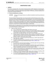
Figure 32-421
Brake Assembly - Serials 1005 thru 1600 before SB2X-32-13 and before SB2X-32-21 (1 of 3)
If temperature indicator is black and/or
shows signs of adhesion loss,
replace the temperature indicator.
NOTE
2
SR20_MM32_1044H
14
15
16
13
7
12
1
10
11
2
3
4
5
6
8
9
LEGEND
1. Bolt
2. Washer
3. Fitting
4. Cylinder
5. O-Ring
6. Piston
7. Rivet
8. Nut
9. Seat, Bleeder
10. Screw, Bleeder
11. Cap, Bleeder
12. Anchor Bolt
13. Torque Plate
14. Pressure Plate
15. Lining
16. Back Plate
17. Temperature Indicator (330°F/Blue)
17
Serials 1005 thru 1600 before
SB2X-32-13 and before SB2X-32-21.
Serials 1005 thru 1592 after SB 2X-32-14,
Serials 1593 thru 1600.
A
CB

CIRRUS AIRPLANE MAINTENANCE MANUAL MODEL SR20
32-42
Page 19
Serials 1005 - 1600 after SB2X-32-13 and before
SB2X-32-21, Serials 1601 - 2240 before SB2X-32-21
EFFECTIVITY:
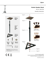
Figure 32-421
Brake Assembly - Serials 1005 - 1600 after SB2X-32-13 and before SB2X-32-21, Serials 1601 - 2240 before SB2X-32-21 (2 of 3)
If temperature indicator is black and/or shows signs of
adhesion loss, replace the temperature indicator.
NOTE
SR20_MM32_2298E
LEGEND
1. Bolt
2. Washer
3. Fitting
4. Cylinder
5. O-Ring
6. Piston
8. Nut
9. Seat, Bleeder
10. Screw, Bleeder
11. Cap, Bleeder
12. Anchor Bolt
13. Torque Plate
14. Pressure Plate
15. Lining
16. Back Plate
17. Temperature Indicator (330°F/Blue)
18. Temperature Indicator (300°F/Yellow)
1
2
2
3
4
5
6
14
15
16
13
12
17
11
10
9
8
Serials 1005 thru 1600 after SB2X-32-13 and
before SB2X-32-21, Serials 1601 thru 2240 before SB2X-32-21.
18
Serials 1005 thru 1592 after SB 2X-32-14,
Serials 1593 thru 2240.
Serials 1005 thru 2030 after SB 2X-05-01,
Serials 2031 thru 2240.
15 Dec 2014

32-42
Page 20
Serials 1005 thru 2240 after SB2X-32-21, 2241 & subs
EFFECTIVITY:
CIRRUS AIRPLANE MAINTENANCE MANUAL MODEL SR20
15 Dec 2014
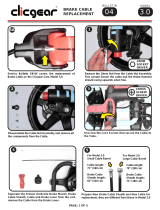
Figure 32-421
Brake Assembly - Serials 1005 thru 2240 after SB2X-32-21, 2241 & subs (3 of 3)
C1
C1
22
25
1
BRAKE LINE
(REF)
23
6
22
21
20
16
19
3
10
24
2
If temperature indicator is black and/or
shows signs of adhesion loss, replace
the temperature indicator.
NOTE
SR20_MM32_3622
LEGEND
2. Washer
3. Fitting
4. Cylinder
6. Piston
10. Screw, Bleeder
16. Back Plate
19. Screw
20. Back Stop
21. Cotter Pin
22. Brake Pad
23. Seal
24. Temperature Indicator (450° Red)
25. Brake Disc
2
4
Serials 1005 thru 2240 after SB2X-32-21, 2241 & subs.
VIEW
C1
C
DETAIL
1
/