Page is loading ...

CIRRUS AIRPLANE MAINTENANCE MANUAL MODEL SR20
57-10
Page 1
All
EFFECTIVITY:
WING STRUCTURE
1. DESCRIPTION
The wing is constructed in a conventional spar, rib, and shear section arrangement. The upper and lower
skins are bonded to the spar, ribs, and aft shear web forming a torsion box that carries all of the wing bend-
ing and torsion loads. The rear shear webs are similar in construction but do not carry through the fuse-
lage.
The wing spar is manufactured in one piece and is continuous from wing tip to wing tip. The wing spar
passes under the fuselage below the two front seats and is attached to the fuselage in two locations. Lift
and landing loads are carried by the single carry-through spar, plus a pair of rear shear webs (one on each
wing) attached to the fuselage. The wing spar is laminated epoxy/glass fiber (Serials 1005 thru 1885) or
laminated epoxy/carbon fiber (Serials 1886 & subs) in a C-section.
The wing’s belly closeout panel is bonded (Serials 1005 thru 1422) or bolted (Serials 1423 & subs) to the
fuselage structure after wing attachment and provides a continuous load path along the bottom of the fuse-
lage.
15 Jun 2010

57-10
Page 2
All
EFFECTIVITY:
CIRRUS AIRPLANE MAINTENANCE MANUAL MODEL SR20
15 Jun 2010
2. MAINTENANCE PRACTICES
A. Wing Assembly
(1) Removal - Wing Assembly
(a) Switch BAT 1, BAT 2, and AVIONICS master switches to OFF position.
(b) Pull all circuit breakers.
(c) Ensure parking brake is in OFF position and wheels are blocked.
(d) Remove engine cowling. (Refer to 71-10)
(e) Disconnect battery 1. (Refer to 24-30)
(f) Set fuel selector valve to OFF position.
(g) De-fuel airplane. (Refer to 12-10)
(h) Remove ailerons. (Refer to 57-50)
(i) Remove flaps. (Refer to 57-50)
(j) Perform Inspection/Check - Tip-to-Tip Measurement. Retain obtained values for compari-
son following reassembly. (Refer to 57-10)
(k) Perform Inspection/Check - Wing Angle of Incidence and Decalage Measurement. Retain
obtained values for comparison following reassembly. (Refer to 57-10)
(l) Remove main gear fairings. (Refer to 32-10)
(m) Remove nose gear fairing. (Refer to 32-20)
CAUTION: Ensure hands are clean while working with interior components.
(n) Remove crew and passenger seats. (Refer to 25-10)
(o) Remove cabin floor covering. (Refer to 25-10)
(p) Remove access panels CF2L, CF2R, CF3R, CF3C, CF3L, and CF5. (Refer to 06-00)
(q) Remove screws securing circuit breaker panel closed.
(r) Serials 1148 thru 1422 w/ Century HSI: Disconnect HSI gyro slaving amplifier. (Refer to
34-50)
1
Disconnect HSI gyro slaving amplifier wire from gyro slaving amplifier mounted to
access panel CF2R.
2
Stow HSI gyro slaving amplifier wire forward.
(s) Remove kick plates. (Refer to 25-10)
(t) Remove cabin trim panels from spar tunnel forward. (Refer to 25-10)
(u) Drain brake hydraulic fluids. (Refer to 12-10)
(v) Remove wing root fairings. (Refer to 53-50)
(w) Disassemble aileron connections. (Refer to 27-10)
1
At access hole CF4C, disconnect aft aileron cable turnbuckle.
2
At access hole CF4C, remove cotter pin, washer, and cable retainer clevis pin from
LH and RH kickout pulley assembly and remove cable from pulley.
Note: To facilitate re-installation, mark location of interconnect bungee
clamps on RH aileron cable.
3
Serials 1005 thru 1885: At access hole CF3C, disconnect rudder/aileron intercon-
nect bungee from RH aileron cable at forward and aft locations. (Refer to 27-20)
4
At access hole CF3C, disconnect forward LH and RH aileron turnbuckles.
5
Stow disconnected cables to wing and forward of wing spar tunnel.
(x) Disassemble rudder connections. (Refer to 27-20)
1
At access hole CF5, disconnect LH and RH rudder cable turnbuckles.

CIRRUS AIRPLANE MAINTENANCE MANUAL MODEL SR20
57-10
Page 3
All
EFFECTIVITY:
Note: Serials 1005 thru 1885: To facilitate re-installation, mark location of
interconnect bungee clamps on RH rudder cable.
2
Serials 1005 thru 1885: At access hole CF3C, disconnect rudder/aileron intercon-
nect bungee from RH rudder cable. (Refer to 27-20)
3
Stow disconnected cables aft and forward of wing spar tunnel.
(y) Disassemble elevator connections. (Refer to 27-30) (Refer to 27-30)
1
At access hole CF5, disconnect LH and RH elevator cable turnbuckles.
2
Stow disconnected cables aft and forward of wing spar tunnel.
(z) Remove flap torque tubes. (Refer to 27-50)
1
At access hole CF4C, remove bolt, washers, spacer, and nut securing torque tubes
to torque tube coupler.
2
At wing root, remove bolt, washers, spacer, and nut securing thrust collar and torque
tube end fitting to torque tube. Repeat on opposite side.
3
Remove LH and RH torque tubes.
(aa) Serials 1005 thru 1885: Disconnect aft fuselage wiring harness.
CAUTION: Label all wires and pins before disconnecting to facilitate re-installation.
1
At access hole CF2R, disconnect J666, J667, and J697.
2
At access hole CF2R, locate ground wire PG650-12N terminal ring and remove
attaching hardware.
3
Serials 1005 thru 1422: At access holes CF2R and CF3R, use a mirror to locate and
remove adel clamps and cable ties securing aft fuselage wiring harness forward and
aft of the wing spar tunnel.
4
Stow disconnected wires forward and aft of the wing spar tunnel.
(ab) Serials 1886 & subs: Disconnect aft fuselage wiring harness.
CAUTION: Label all wires and pins before disconnecting to facilitate re-installation.
1
At access hole CF3R, disconnect J666, J667, and J1049.
2
At access hole CF3R, locate ground wire PG650-12N terminal ring and remove
attaching hardware.
3
Stow disconnected wires forward and aft of the wing spar tunnel.
(ac) Serials 1337 thru 1422 w/ PFD: Disconnect magnetometer cable.
1
At access hole CF3R, disconnect jack J729 for magnetometer cabling and remove
cable ties.
2
De-pin plug P729 to enable magnetometer cabling to pass forward through spar tun-
nel bulkhead connector.
3
De-pin jack J729 to enable magnetometer cabling to pass aft through fuselage bulk-
head connector.
4
Stow disconnected wires forward of the wing spar tunnel and at wing.
(ad) Serials 1423 & subs: Disconnect magnetometer cable.
1
At access hole CF3R, disconnect jack J729 for magnetometer cabling and remove
cable ties.
2
Route plug P729 on magnetometer cabling forward of wing spar tunnel.
3
Remove backshell from jack J729 to enable magnetometer cabling to pass aft
through fuselage bulkhead connector.
4
Stow disconnected wires forward of the wing spar tunnel and at wing.
(ae) Serials 2065 & subs w/ Air Conditioning: Disconnect wiring harness for condenser.
19 Sep 2010

57-10
Page 4
All
EFFECTIVITY:
CIRRUS AIRPLANE MAINTENANCE MANUAL MODEL SR20
19 Sep 2010
1
At access hole CF3R, disconnect plug P1005 for condenser cabling and remove
cable ties.
2
Remove backshell from plug P1005 to enable condenser cabling to pass forward
through spar tunnel bulkhead connector.
3
Stow disconnected wires forward and aft of the wing spar tunnel.
(af) Serials 1005 thru 1885: Disconnect wiring harnesses for wing.
CAUTION: Label all wires and pins before disconnecting to facilitate re-installation.
1
At access hole CF4L, disconnect J300 from connector on LH longeron and remove
cable ties.
2
At access hole CF4R, disconnect J400 from connector on RH longeron and remove
cable ties.
3
De-pin J300 and J400 to enable wires to pass through fuselage bulkhead connector.
4
Stow disconnected wires at each wing and forward of the wing spar tunnel.
(ag) Serials 1886 & subs: Disconnect wiring harnesses for wing.
CAUTION: Label all wires and pins before disconnecting to facilitate re-installation.
1
At access hole CF2L, disconnect J300 from connector and remove cable ties.
2
At access hole CF2R, disconnect J400 from connector and remove cable ties.
3
De-pin J300 and J400 to enable wires to pass through fuselage bulkhead connector.
4
Stow disconnected wires at each wing and forward of the wing spar tunnel.
(ah) Serials 1005 & subs w/ Stormscope System: Disconnect wiring harness for Stormscope.
1
At access hole CF2R, disconnect J668 and remove cable ties.
2
Serials 1337 & subs w/o PFD: At access hole CF2R, disconnect J557 and remove
cable ties.
3
Serials 1337 & subs w/o PFD: At access hole CF2R, disconnect P698 and remove
cable ties.
4
Stow disconnected wires aft and forward of the wing spar tunnel.
(ai) Disassemble Pitot-Static System. (Refer to 34-10)
1
Remove fittings on pitot-static lines to enable lines to pass through fuselage grom-
met.
2
At access hole CF3L, disconnect Pitot-Static System lines.
3
Stow pitot line aft of wing spar tunnel and to wing.
4
Stow static line aft of wing spar tunnel.
(aj) Serials 1005 thru 1885: Disconnect ELT remote control panel indicator connection.
1
On circuit breaker panel, disconnect ELT remote control panel indicator connector
and grounding terminal ring. (Refer to 25-60)
2
Remove cable ties and stow ELT remote control panel indicator cable aft of wing
spar tunnel.
(ak) Serials 1268 thru 1885: Disconnect battery 2.
1
On circuit breaker panel, disconnect battery 2 power cable. (Refer to 24-30)
2
On RH side of forward longerons, disconnect battery 2 ground wire from P602 con-
nector secured to firewall. (Refer to 24-30)
3
Remove cable ties and stow battery 2 power cable and ground wire aft of wing spar
tunnel.
(al) Serials 1886 & subs: Disconnect battery 2.
1
At access panel CF3R, disconnect jack J847 for battery 2 and remove cable ties.

CIRRUS AIRPLANE MAINTENANCE MANUAL MODEL SR20
57-10
Page 5
All
EFFECTIVITY:
2 At access panel CF3R, de-pin jack J847 to enable battery 2 wiring to pass through
spar tunnel bulkhead connector.
3
Stow disconnected wires aft and forward of the wing spar tunnel.
(am) Serials 1005 thru 1885: Disconnect marker beacon antenna.
1
Below radio rack, disconnect marker beacon antenna cable. (Refer to 34-30)
2
Remove cable ties and stow marker beacon antenna cable aft of wing spar tunnel.
(an) Serials 1005 thru 1885: Disconnect COM2 antenna.
1
At access panel CF5, disconnect COM 2 antenna cable from COM 2 antenna.
(Refer to 34-50)
2
Remove cable ties and stow COM 2 antenna cable forward of wing spar tunnel.
(ao) Serials 1005 thru 1885: Disconnect VOR/LOC antenna.
Note: Ensure VOR/LOC antenna cable is retained above tail when remov-
ing antenna.
1
Remove VOR/LOC antenna. (Refer to 34-50)
2
Tie string to VOR/LOC antenna cable and route down tail. Tie upper end of string to
upper tail. Untie string at RH empennage access panel and stow in area to facilitate
re-installation of antenna cable.
3
Remove cable ties and stow VOR/LOC antenna cable forward of wing spar tunnel.
(ap) Center-aft of main wing spar, disconnect fuel supply and return lines. (Refer to 28-20)
(aq) Disassemble Stall Warning System connections. (Refer to 27-31)
1
At access hole CF2R, disconnect stall warning line to wing.
2
Remove fitting on stall warning line to enable line to pass through fuselage bulkhead
connector.
3
Remove cable ties and stow stall warning line into the wing.
(ar) Serials 1005 thru 1885: Disconnect environmental ducts. (Refer to 21-20)
1
Acquire necessary tools, equipment, and supplies.
2
Serials 1005 thru 1632, 1634 thru 1636: Adjacent to CF2L and CF2R access holes,
pry and remove adhesive securing environmental duct to fresh air inlet tee on LH
and RH fuselage wall.
3
Serials 1005 thru 1632, 1634 thru 1636: Disconnect environmental ducts from fresh
air inlet tee(s).
4
Serials 1633, 1637 & subs: Adjacent to CF2R access hole, pry and remove adhe-
sive securing environmental duct to RH fuselage wall.
(as) Serials 1005 thru 1422 w/ Sandel HSI: Disconnect HSI gyro slaving amplifier and remote
gyro. (Refer to 34-50)
1
At access hole CF2R, disconnect data cable from HSI gyro slaving amplifier.
2
At access hole CF3R, disconnect data cable HSI remote gyro.
3
Stow data cables forward of wing spar tunnel.
(at) Serials 1005 thru 1422: Remove belly closeout panel. (See Figure 57-101)
Description P/N or Spec. Supplier Purpose
Putty Knife - Any Source Prying
Utility Knife - Any Source Cutting
19 Sep 2010

57-10
Page 6
All
EFFECTIVITY:
CIRRUS AIRPLANE MAINTENANCE MANUAL MODEL SR20
19 Sep 2010
1
Acquire necessary tools, equipment, and supplies.
2
From beneath the airplane looking up through the gap between LH wing root and
fuselage, determine where the forward and aft plane of the wing spar intersects with
the belly closeout panel and mark. Repeat on RH side.
3
To prevent possible damage to main spar, offset forward mark 0.25 inch (0.64 cm)
forward, and aft cut line 0.25 inch (0.64 cm) aft.
4
At offset marks, use chalk snap line to locate cut lines across width of belly closeout
panel.
CAUTION: Ensure all cabling, wires, and tubes routed through wing spar are
removed before cutting into belly closeout panel.
Damage to the main spar may render the wing unusable. Do not cut
into the wing spar, wing spar tunnel, or bonding flanges.
If spar is damaged, contact Cirrus Design Customer Service for dis-
position.
5
Using die grinder, cut belly closeout panel at marked lines.
Note: If screws are embedded in adhesive, it may be necessary to cut
screws and drill them out.
6
Use magnet to locate mounting hardware and chisel to expose screw heads.
7
At determined screw head locations, sand paint and bodywork off.
8
Remove hardware fastening belly closeout panel to fuselage.
CAUTION: Do not damage underlying laminate.
9
Using chisel, remove remaining portion of belly closeout panel from fuselage.
(au) Serials 1423 thru 2029: Remove belly closeout panel. (See Figure 57-101)
1
Acquire necessary tools, equipment, and supplies.
Description P/N or Spec. Supplier Purpose
Chalk Snap Line - Any Source Locate Cut Lines
Die Grinder - Any Source Cutting
Metal Cut-Off Wheel and Arbor 2.0 inches (5.1 cm) Any Source Cutting
Magnet - Any Source Locate Hard-
ware
Blunt-Edged Chisel - Any Source Cutting
Sandpaper 400-grit Any Source Abrasion
Description P/N or Spec. Supplier Purpose
Blunt-Edged Chisel - Any Source Cutting
Die Grinder - Any Source Cutting

CIRRUS AIRPLANE MAINTENANCE MANUAL MODEL SR20
57-10
Page 7
All
EFFECTIVITY:
Note: The two middle mounting screws on the forward and aft sides of belly
closeout panel are covered by a strip of expanded metal mesh (EMM)
for lightning protection. The screw heads must be located and
exposed prior to belly closeout panel removal.
2
At forward and aft belly closeout panel seam, sand at seam along row of installation
screws to locate adjacent screws covered by EMM.
3
Mark cut lines on EMM where EMM overlaps the space between belly closeout
panel and fuselage.
CAUTION: Ensure all cabling, wires, and tubes routed through wing spar are
removed before cutting through EMM.
Damage to the main spar may render the wing unusable. Do not cut
into the wing spar, wing spar tunnel, or bonding flanges.
If spar is damaged, contact Cirrus Design Customer Service for dis-
position.
4
Using die grinder, carefully cut through EMM at marked lines.
5
Remove screws, washers, and nuts securing belly closeout panel to fuselage.
(av) Serials 2030 & subs: Remove screws, washers, and nuts securing belly closeout panel to
fuselage. (See Figure 57-101)
Metal Cut-Off Wheel and Arbor 2.0 inches (5.1 cm) Any Source Cutting
Sandpaper 80-grit Any Source Abrasion
Description P/N or Spec. Supplier Purpose
19 Sep 2010

57-10
Page 8
Serials 1005 thru 1422
EFFECTIVITY:
CIRRUS AIRPLANE MAINTENANCE MANUAL MODEL SR20
15 Jun 2010
Figure 57-101
Belly Closeout Panel Removal - Serials 1005 thru 1422 (Sheet 1 of 3)
SR20_MM57_1653A
0.25 inch
Offset mark away from wing spar 0.25 inch (0.64 cm).
NOTE
Mark where forward and aft plane of wing spar
intersects with belly closeout.
Mark cut lines across belly closeout.
AFT PLANE OF
WING SPAR
FORWARD PLANE
OF WING SPAR
WING SPAR
BELLY CLOSEOUT
Serials 1005 thru 1422.

CIRRUS AIRPLANE MAINTENANCE MANUAL MODEL SR20
57-10
Page 9
Serials 1423 thru 2029
EFFECTIVITY:
Figure 57-101
Belly Closeout Panel Removal - Serials 1423 thru 2029 (Sheet 2 of 3)
SR20_MM57_1875B
LEGEND
1. Belly Closeout Panel
2. Screw
3. Washer
4. Nut
4
2
3
CUT LINE
FUSELAGE
NOTE
Mark cut lines where EMM overlaps space between
belly closeout panel and fuselage.
EMM
FUSELAGE
1
WING SPAR
Sand at belly closeout panel seam along row of installation
screws to locate adjacent screws covered by EMM.
Serials 1423 thru 2029.
15 Jun 2010

57-10
Page 10
Serials 2030 & subs
EFFECTIVITY:
CIRRUS AIRPLANE MAINTENANCE MANUAL MODEL SR20
15 Jun 2010
Figure 57-101
Belly Closeout Panel Removal - Serials 2030 & subs (Sheet 3 of 3)
SR20_MM57_3188
LEGEND
1. Belly Closeout Panel
2. Screw
3. Washer
4. Nut
4
2
3
FUSELAGEFUSELAGE
1
WING SPAR
Serials 2030 & subs.

CIRRUS AIRPLANE MAINTENANCE MANUAL MODEL SR20
57-10
Page 11
All
EFFECTIVITY:
(aw) Support wing and fuselage. (See Figure 57-102)
1
Acquire necessary tools, equipment, and supplies.
2
Prepare airplane for hoisting. (Refer to 07-20)
CAUTION: To assure stability and safety during hoisting operations, raise air-
plane slowly.
3
Raise airplane enough to place saw horses with foam padding at LH and RH wing
support locations.
Description P/N or Spec. Supplier Purpose
Saw Horses - Any Source Support
High Density Foam Padding - Any Source Protection
15 Jun 2010

57-10
Page 12
All
EFFECTIVITY:
CIRRUS AIRPLANE MAINTENANCE MANUAL MODEL SR20
15 Jun 2010
Figure 57-102
Fuselage Hoist and Wing Support Stands
SR20_MM57_1652A
APPROVED HOISTING
METHOD
APPROVED HOISTING
METHOD
ENGINE MOUNT
FOAM PAD
WING STATION 41
FUSELAGE STATION 289

CIRRUS AIRPLANE MAINTENANCE MANUAL MODEL SR20
57-10
Page 13
All
EFFECTIVITY:
(ax) Detach wing assembly. (See Figure 57-104)
CAUTION: Verify all components routed underneath wing main spar have been discon-
nected and removed.
1
Acquire necessary tools, equipment, and supplies.
2
Serials 1005 thru 1636 w/ SKYWATCH: Remove SKYWATCH cover panel. (Refer to
34-40)
3
Serials 1637 & subs w/o Fan: Remove bolts and washers securing vent assembly
cover to fuselage. (Refer to 21-20)
4
Serials 1637 & subs w/ Fan: Remove bolts and washers securing fan assembly
cover and fan assembly to fuselage. Position fan assembly as required to permit
access to attach fittings. (Refer to 21-20)
5
Serials 2065 & subs w/ Air Conditioning: Remove bolts and washers securing evap-
orator cover and evaporator to fuselage. Position evaporator as required to permit
access to attach fittings. (Refer to 21-50)
6
At aft attach fittings, remove bolt, washer, nut, and cotter pin securing wing to fuse-
lage.
7
At forward attach fittings, remove bolt, washers, spacer, and nut wing to fuselage.
Discard bolt.
CAUTION: When raising fuselage, align wing and fuselage at bolt locations so as
to take tension off bolts and facilitate the wing sliding off smoothly.
While separating wing from fuselage, observe and assist in routing of
wiring and tubing between wing and fuselage.
8
Slowly raise hoist to detach fuselage from wing structure assembly. (See Figure 57-
103)
9
Cover fuselage cradle with foam padding to protect the fuselage surface.
CAUTION: Verify clearance exists at fuselage cradle for transponder antenna
prior to lowering fuselage onto cradle.
10
If necessary for fuselage cradle clearance, remove transponder antenna. (Refer to
34-50)
11
Lower fuselage onto fuselage cradle and tailstand.
12
Secure tailstand to tail tiedown. (Refer to 07-10)
Description P/N or Spec. Supplier Purpose
Tailstand 300 pounds (136 kg)
minimum weight
Any Source Support
Fuselage Cradle 2000 pounds (907 kg)
capacity
Any Source Support
Casters - Any Source Mobility
High Density Foam Padding - Any Source Protection
19 Sep 2010

57-10
Page 14
All
EFFECTIVITY:
CIRRUS AIRPLANE MAINTENANCE MANUAL MODEL SR20
15 Jun 2010
Figure 57-103
Fuselage and Wing Separation
SR20_MM57_1694B
TAIL STAND
FOAM PAD
FUSELAGE
CRADLE
WING STATION 41
FOAM PAD
TAIL TIEDOWN
NOTE
Serials 1005 thru 1877, 1879 thru 1885:
Verify clearance exists at fuselage cradle for
transponder antenna. If necessary, remove
transponder antenna prior to lowering fuselage
onto cradle.

CIRRUS AIRPLANE MAINTENANCE MANUAL MODEL SR20
57-10
Page 15
All
EFFECTIVITY:
(2) Installation - Wing Assembly (See Figure 57-104)
WARNING:
Installation of the wing assembly requires a test flight performed by a Cirrus
Design certified test pilot. Contact Cirrus Design prior to performing mainte-
nance to schedule test flight.
(a) Acquire necessary tools, equipment, and supplies.
(b) Position wing assembly under fuselage.
CAUTION: While lowering fuselage, verify clearance and route wiring and tubing from
wing through fuselage bulkhead fittings. (See Figure 57-105)
(c) Lower fuselage onto wing assembly.
(d) Install wing attach guide pins at the forward wing attach location to facilitate alignment of
wing and fuselage attach points.
(e) Secure forward wing attach hardware.
CAUTION: Ensure Belleville washers are installed in correct orientation. Position
washer next to bolt head with beveled cut towards bolt head.
1
Remove wing attach guide pins.
2
Install new bolts with existing washers, spacers, and nuts securing wing to fuselage.
3
Tighten nut to 400 - 500 in-lb (45 - 56 Nm).
4
Verify bolt shows at least one thread past end of nut when installed.
5
Serials 1005 thru 1636 w/ SKYWATCH: Install SKYWATCH cover panel. (Refer to
34-40)
6
Serials 1637 & subs w/o Fan: Install bolts and washers securing vent assembly
cover to fuselage. (Refer to 21-20)
7
Serials 1637 & subs w/ Fan: Install bolts and washers securing fan assembly cover
and fan assembly to fuselage. (Refer to 21-20)
8
Serials 2065 & subs w/ Air Conditioning: Install bolts and washers securing evapora-
tor cover and evaporator to fuselage. (Refer to 21-50)
(f) Secure aft wing attach hardware.
CAUTION: Hard contact between aft wing attach fitting and bracket is not allowed on
forward side of bracket. Do not compress aft wing attach fittings by over-
tightening.
1
Install bolts, washers, and nuts securing wing to fuselage.
2
Tighten nut until snug then loosen nut enough to install new cotter pin.
3
Verify gap under bolt head or nut does not exceed 0.10 inch (2.54 mm).
Description P/N or Spec. Supplier Purpose
Wing Attach Guide Pins T6859-1 Cirrus Design Alignment
Bolts, Forward Wing Attach MS20014-46
alternate for
NAS6614D46
Any Source Replacement
19 Sep 2010

57-10
Page 16
All
EFFECTIVITY:
CIRRUS AIRPLANE MAINTENANCE MANUAL MODEL SR20
15 Jun 2010
Figure 57-104
Wing Attach
Serials 1005 thru 1267: Washer installation optional.
Serials 1268 & subs: Washer installation required.
Hard contact between attach fitting and bracket not
allowed on forward side of bracket.
Do not compress attach fittings.
Verify gap under bolt head or nut does not
exceed 0.10 inch.
NOTE
Position washer with beveled cut towards bolt head.
2
1
SR20_MM57_1247B
AFT ATTACH BRACKET,
FUSELAGE (REF)
WING MAIN
SPAR (REF)
WING (REF)
FWD ATTACH FITTING (REF)
AFT ATTACH FITTING (REF)
5
4
6
2
5
2
3
2
LEGEND
1. Bolt
2. Washer
3. Belleville Washer
4. Spacer
5. Nut
6. Cotter Pin
1
SPACER (REF)
SEAT ATTACH
(REF)
WING ATTACH
PLATE (REF)

CIRRUS AIRPLANE MAINTENANCE MANUAL MODEL SR20
57-10
Page 17
All
EFFECTIVITY:
Figure 57-105
Fuselage to Wing Connectivity
SR20_MM57_2195B
APPROVED HOISTING
METHOD
FUSELAGE STATION 289
APPROVED HOISTING
METHOD
ENGINE MOUNT
RH FUSELAGE
LH FUSELAGE
ENVIRONMENTAL DUCT
FLAP TORQUE
TUBE
PITOT LINE
AND
W300 WIRING HARNESS
FLAP TORQUE
TUBE
ICE PROTECTION LINE
MAGNETOMETER
AND W400 WIRING HARNESS
ENVIRONMENTAL
DUCT
STALL WARNING
AND
ICE PROTECTION LINE
Serials 1005 thru 1632, 1634 thru 1636 only.
NOTE
Serials 1005 thru 1877, 1879 thru 1885 only.
15 Jun 2010

57-10
Page 18
All
EFFECTIVITY:
CIRRUS AIRPLANE MAINTENANCE MANUAL MODEL SR20
15 Jun 2010
(g) Remove wing supports and hoisting straps.
(h) Perform Inspection/Check - Tip-to-Tip Measurement. Compare with values obtained previ-
ously. (Refer to 57-10)
(i) Perform Inspection/Check - Wing Angle of Incidence and Decalage Measurement. Com-
pare with values obtained previously. (Refer to 57-10)
(j) Serials 1005 thru 1422 w/ Sandel HSI: Connect HSI gyro slaving amplifier and remote
gyro. (Refer to 34-50)
1
Route HSI remote gyro wire aft to access hole CF3R and connect to remote gyro.
2
Route HSI gyro slaving amplifier wire aft to access hole CF2R and connect to gyro
slaving amplifier.
(k) Serials 1005 thru 1885: Connect environmental ducts. (Refer to 21-20)
1
Acquire necessary tools, equipment, and supplies.
2
Serials 1005 thru 1636: Adjacent to CF2L and CF2R, connect environmental ducts
to LH and RH fresh air inlet tee.
3
Serials 1637 thru 1885: Adjacent to CF2R, connect environmental duct to RH fuse-
lage wall.
4
Secure ducts and tees to fuselage wall with latex caulk or RTV sealant.
(l) Assemble Stall Warning System connections. (Refer to 27-31)
1
Route Stall Warning System line to access hole CF2R from right wing.
2
At access hole CF2R, install fitting and connect wing stall warning line.
3
Secure lines with cable ties as required.
(m) Center-aft of main wing spar, connect fuel supply and return lines. (Refer to 28-20)
(n) Serials 1005 thru 1885: Connect VOR/LOC antenna.
1
Route VOR/LOC antenna cable aft of wing spar tunnel.
2
Replace cable ties for line as required.
3
Tie lower string end stowed in empennage to VOR/LOC antenna cable. Carefully
pull upper string end to route VOR/LOC antenna cable up tail.
4
Connect antenna cable to VOR/LOC antenna and discard string. Install VOR/LOC
antenna. (Refer to 34-50)
(o) Serials 1005 thru 1885: Connect COM2 antenna.
1
Route COM 2 antenna cable aft of wing spar tunnel.
2
Replace cable ties for line as required.
3
At COM 2 antenna, connect COM 2 antenna connector. (Refer to 34-50)
(p) Serials 1005 thru 1885: Connect marker beacon antenna.
1
Route marker beacon antenna cable forward of wing spar tunnel.
2
Replace cable ties for line as required.
Description
P/N or
Spec.
Supplier Purpose
Caulking Gun - Any Source Application
Latex Caulk
alternative for
RTV Sealant
151-8273 Sherwin Williams Company
Ashland, KY 41101
606-324-3179
Sealing
736 RTV Dow Corning Corporation
Midlands, MI 48686
517-496-6000

CIRRUS AIRPLANE MAINTENANCE MANUAL MODEL SR20
57-10
Page 19
All
EFFECTIVITY:
3 Below radio rack, connect marker beacon antenna cable. (Refer to 34-30)
(q) Serials 1005 thru 1885: Connect battery 2.
1
Route battery 2 cable forward of wing spar tunnel.
2
Replace cable ties for lines as required.
3
On circuit breaker panel, connect battery 2 power cable. (Refer to 24-30)
4
Serials 1268 & subs: On RH side of forward longerons, connect battery 2 ground
wire to P602 connector secured to firewall. (Refer to 24-30)
(r) Serials 1886 & subs: Connect battery 2.
1
Route secondary battery power/ground forward of wing spar tunnel.
2
Replace cable ties for lines as required.
3
At access panel CF3R, re-pin jack J847 to enable battery 2 wiring to pass through
spar tunnel bulkhead connector.
4
At access panel CF3R, connect jack J847 for battery 2.
(s) Serials 1005 thru 1885: Connect ELT remote control panel indicator connection.
1
Route ELT remote control panel indicator cable forward of wing spar tunnel.
2
On circuit breaker panel, connect ELT remote control panel indicator connector and
grounding terminal ring. (Refer to 25-60)
3
Replace cable ties for line as required.
(t) Assemble Pitot-Static System. (Refer to 34-10)
1
Route pitot line from left wing and forward to access hole CF3L.
2
Route static line forward to access hole CF3L.
3
At access hole CF3L, install fittings and connect Pitot-Static lines.
4
Secure lines with cable ties as required.
(u) Serials 1005 & subs w/ StormScope System: Assemble wiring harness for Stormscope.
1
Route Stormscope wires to access hole CF2R.
2
At access hole CF2R, connect J668.
3
Serials 1337 & subs w/o PFD: At access hole CF2R, connect J557 and P698.
4
Secure wire harnesses with cable ties as required.
(v) Serials 1005 thru 1885: Assemble wiring harnesses for wing.
1
Route wiring harness from LH wing to access hole CF4L.
2
Route wiring harness from RH wing to access hole CF4R.
3
Re-pin J300 and J400.
4
At access hole CF4L, connect J300 to connector on LH longeron.
5
At access hole CF4R, connect J400 to connector on RH longeron.
6
Secure wire harnesses with cable ties as required.
(w) Serials 1886 & subs: Assemble wiring harnesses for wing.
1
At access hole CF2L, connect J300 connector.
2
At access hole CF2R, connect J400 connector.
3
Secure wire harnesses with cable ties as required.
(x) Serials 2065 & subs w/ Air Conditioning: Connect wiring harness for condenser.
1
Route condenser cabling forward to access hole CF3R.
2
Assemble P1005 connector.
3
At access hole CF3R, connect plug P1005 for condenser cabling.
4
Secure wire harnesses with cable ties as required.
(y) Serials 1337 thru 1422 w/ PFD: Assemble magnetometer cable.
1
Route magnetometer cables to access hole CF3R.
2
At access hole CF3R, re-pin J729 and P729.
3
Connect J729 to P729.
19 Sep 2010

57-10
Page 20
All
EFFECTIVITY:
CIRRUS AIRPLANE MAINTENANCE MANUAL MODEL SR20
19 Sep 2010
(z) Serials 1423 & subs: Assemble magnetometer cable.
1
Route magnetometer cables to access hole CF3R.
2
At access hole CF3R, install backshell onto J729.
3
Connect J729 to P729.
(aa) Serials 1005 thru 1885: Assemble aft fuselage wiring harness.
1
Route aft fuselage wiring harness to access hole CF2R.
2
At access hole CF2R, secure ground wire PG650-12N terminal ring with attaching
hardware and cover with heatshrink material.
3
At access hole CF2R, connect J666, J667, and J697.
CAUTION: Only secure wiring bundles with adel clamps. Ensure control cables
for rudder, elevator, and aileron are not secured by adel clamps.
4
Serials 1005 thru 1422: Install adel clamps and cable ties securing aft fuselage wir-
ing harness forward and aft of the wing spar tunnel.
(ab) Serials 1886 & subs: Assemble aft fuselage wiring harness.
1
Route aft fuselage wiring harness to access hole CF3R.
2
At access hole CF3R, secure ground wire PG650-12N terminal ring with attaching
hardware and cover with heat shrink material.
3
At access hole CF3R, connect J666, J667, and J1049.
4
Only secure wiring bundles with adel clamps. Ensure control cables for rudder, ele-
vator, and aileron are not secured by adel clamps.
(ac) Assemble flap torque tubes. (Refer to 57-50)
1
Install LH and RH torque tubes.
2
At wing root, position thrust collar and torque tube end fitting to torque tube and
secure with bolt, washers, spacer, and nut. Repeat on opposite side
3
At access hole CF4C, torque tubes to torque tube coupler and secure with bolt,
washers, spacer, and nut.
(ad) Install flaps. (Refer to 57-50)
(ae) Assemble aileron connections. (Refer to 27-10)
1
Route disconnected cables stowed from wing to access hole CF3C.
2
At access hole CF3C, connect LH and RH aileron cable turnbuckles.
3
Route disconnected cables stowed in aft area to access hole CF4C.
4
At access hole CF4C, connect aft aileron cable turnbuckle.
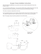
5
Serials 1005 thru 1885: At access hole CF3C, connect rudder/aileron interconnect
bungee to RH aileron cable at forward and aft locations. (Refer to 27-20)
6
At access hole CF4C, install cable retainer pins, washers, and cotter pins to LH and
RH kickout pulley assemblies.
(af) Install ailerons. (Refer to 57-50)
(ag) Assemble elevator connections. (Refer to 27-30)
1
Route disconnected cables to access hole CF5.
2
Connect LH and RH elevator cables turnbuckles.
(ah) Assemble rudder connections. (Refer to 27-20)
1
Route disconnected cables to access hole CF5.
2
At access hole CF5, connect LH and RH elevator cable turnbuckles.
3
Serials 1005 thru 1885: At access hole CF3C, connect rudder/aileron interconnect
bungee to RH rudder cable. (Refer to 27-20)
(ai) Inspect fuel system for leaks. (Refer to 28-10)
(aj) Bleed brake system. (Refer to 32-42)
/