Page is loading ...

AIRPLANE INFORMATION MANUAL
for the
CIRRUS DESIGN SR20
Aircraft Serials 2016 and Subsequent with
Cirrus Perspective Avionics System
At the time of issuance, this Information Manual was harmo-
nized with the SR20 Pilot's Operating Handbook September
2011 (P/N 11934-004), and will not be kept current.
Therefore, this Information Manual is for reference only and can-
not be used as a substitute for the official Pilot's Operating
Handbook and FAA Approved Airplane Flight Manual.
Information Manual
P/N 13999-004 September 2011

Copyright © 2011 - All Rights Reserved
Cirrus Design Corporation
4515 Taylor Circle
Duluth, MN 55811

P/N 13999-004 Info Manual 1-1
Cirrus Design Section 1
SR20 General
Section 1
General
Table of Contents
Introduction ........................................................................................ 3
The Airplane....................................................................................... 7
Engine............................................................................................. 7
Propeller ......................................................................................... 7
Fuel................................................................................................. 8
Oil .................................................................................................. 8
Maximum Certificated Weights ....................................................... 8
Cabin and Entry Dimensions .......................................................... 8
Baggage Spaces and Entry Dimensions ........................................ 8
Specific Loadings............................................................................ 8
Symbols, Abbreviations and Terminology.......................................... 9
General Airspeed Terminology and Symbols ................................. 9
Meteorological Terminology.......................................................... 10
Engine Power Terminology........................................................... 11
Performance and Flight Planning Terminology............................. 11
Weight and Balance Terminology................................................. 12
September 2011

1-2 P/N 13999-004 Info Manual
Section 1 Cirrus Design
General SR20
September 2011
Intentionally Left Blank

Cirrus Design Section 1
SR20 General
P/N 13999-004 Info Manual 1-3
Introduction
This section contains information of general interest to pilots and
owners. You will find the information useful in acquainting yourself with
the airplane, as well as in loading, fueling, sheltering, and handling the
airplane during ground operations. Additionally, this section contains
definitions or explanations of symbols, abbreviations, and terminology
used throughout this handbook.
• Note •
For specific information regarding the organization of this
Handbook, revisions, supplements, and procedures to be
used to obtain revision service for this handbook, See
“Revising the Handbook” on page 3 of the “Foreword” section.
All liquid volumes referenced in this publication are expressed
in United States Customary Units, e.g., U.S. Gallons.
September 2011

1-4 P/N 13999-004 Info Manual
Section 1 Cirrus Design
General SR20
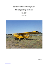
Figure 1-1
Airplane Three View
74 inches 3-BLADE
188 cm
38.3 ft
11.67 m
9.1 ft
2.8 m
9 inches (minimum)
23 cm (minimum)
26.0 ft
7.92 m
8.9 ft
2.71 m
NOTE:
• Wing span includes
position and strobe lights.
• Prop ground clearance at
3050 lb - 9 inches (23 cm).
• Wing Area = 144.9 sq. ft.
SR20_FM01_2415
September 2011

Cirrus Design Section 1
SR20 General
P/N 13999-004 Info Manual 1-5
Location Length Width Height Volume
Cabin
122” 49.3” 49.7 137 cu ft
Baggage
Compartment
36” 39.8” 38.5” 32 cu ft
Figure 1-2
Airplane Interior Dimensions
39.8"
49.3"
240220
200
180160140120
16.0"
49.7"
25.0"
38.5"
FS
10.5"
33.4"
39.0"
20.0"
33.3"
32.0"
SR22_FM06_1019
100
222
CABIN DOOR
OPENING
BAGGAGE DOOR
OPENING
20.0"
21.0"
5.0"
Station
Fuselage
September 2011

1-6 P/N 13999-004 Info Manual
Section 1 Cirrus Design
General SR20
Figure 1-3
Turning Radius
9.1 ft. (2.77 m)
0.5 ft. (0.15 m)
24.3 ft. (7.41 m)
7.0 ft. (2.16 m)
RADIUS FOR NOSE GEAR
RADIUS FOR OUTSIDE GEAR
RADIUS FOR INSIDE GEAR
RADIUS FOR WING TIP
TURNING RADII ARE CALCULATED USING ONE BRAKE AND
PARTIAL POWER. ACTUAL TURNING RADIUS MAY VARY AS
MUCH AS THREE FEET.
GROUND TURNING CLEARANCE
SR20_FM01_2413
September 2011

Cirrus Design Section 1
SR20 General
P/N 13999-004 Info Manual 1-7
The Airplane
Engine
Number of Engines.............................................................................. 1
Number of Cylinders............................................................................ 6
Engine Manufacturer ............................................Teledyne Continental
Engine Model ....................................................................... IO-360-ES
Fuel Metering ................................................................... Fuel Injected
Engine Cooling ..................................................................... Air Cooled
Engine Type.................................... Horizontally Opposed, Direct Drive
Horsepower Rating................................................ 200 hp @ 2700 rpm
Propeller
Hartzell
Propeller Type ............................................................. Constant Speed
Two-Blade Propeller:
Model Number................................................... BHC-J2YF-1BF/F7694
Diameter.............................................................76.0” (73.0” Minimum)
Three-Blade Propeller:
Model Number............................................... PHC-J3YF-1MF/F7392-1
Diameter.............................................................74.0” (72.0” Minimum)
Model Number............................................... PHC-J3YF-1RF/F7392-1
Diameter.............................................................74.0” (72.0” Minimum)
September 2011

1-8 P/N 13999-004 Info Manual
Section 1 Cirrus Design
General SR20
Fuel
Total Capacity .............................................58.5 U.S. Gallons (221.0 L)
Total Usable................................................56.0 U.S. Gallons (212.0 L)
Approved Fuel Grades:
100 LL Grade Aviation Fuel (Blue)
100 (Formerly 100/130) Grade Aviation Fuel (Green)
Oil
Oil Capacity (Sump) .............................................8 U.S. Quarts (7.6 L)
Oil Grades:
All Temperatures .............................................SAE 15W-50 or 20W-50
Below 40 ° F (4° C).................................................. SAE 30 or 10W-30
Above 40 ° F (4° C) ...................................................................SAE 50
Maximum Certificated Weights
Maximum Gross for Takeoff...................................... 3050 lb (1383 Kg)
Maximum Baggage Compartment Loading .................... 130 lb (59 Kg)
Standard Empty Weight.............................................. 2050 lb (930 Kg)
Maximum Useful Load................................................ 1000 lb (454 Kg)
Full Fuel Payload .......................................................... 671 lb (304 Kg)
Cabin and Entry Dimensions
Refer to the preceding figures for dimensions of the cabin interior and
entry door openings.
Baggage Spaces and Entry Dimensions
Refer to the preceding figures for dimensions of the cabin interior and
entry door openings
Specific Loadings
Wing Loading..................................................... 22.2 lb per square foot
Power Loading.................................................................15.0 lb per hp
September 2011

Cirrus Design Section 1
SR20 General
P/N 13999-004 Info Manual 1-9
Symbols, Abbreviations and Terminology
General Airspeed Terminology and Symbols
KCAS Knots Calibrated Airspeed is the indicated airspeed
corrected for position and instrument error. Calibrated
airspeed is equal to true airspeed in standard atmosphere
at sea level.
KIAS Knots Indicated Airspeed is the speed shown on the
airspeed indicator. The IAS values published in this
handbook assume no instrument error.
KTAS Knots True Airspeed is the airspeed expressed in knots
relative to undisturbed air which is KCAS corrected for
altitude and temperature.
V
G
Best Glide Speed is the speed at which the greatest flight
distance is attained per unit of altitude lost with power off.
V
O
Operating Maneuvering Speed is the maximum speed at
which application of full control movement will not
overstress the airplane.
V
FE
Maximum Flap Extended Speed is the highest speed
permissible with wing flaps in a prescribed extended
position.
V
NO
Maximum Structural Cruising Speed is the speed that
should not be exceeded except in smooth air, and then
only with caution.
V
NE
Never Exceed Speed is the speed that may not be
exceeded at any time.
V
PD
Maximum Demonstrated Parachute Deployment Speed is
the maximum speed at which parachute deployment has
been demonstrated.
V
S
Stalling Speed is minimum steady flight speed at which
the aircraft is controllable.
V
S
50% Stalling Speed is minimum steady flight speed at which
the aircraft is controllable with 50% flaps.
September 2011

1-10 P/N 13999-004 Info Manual
Section 1 Cirrus Design
General SR20
Meteorological Terminology
V
SO
Stalling Speed is the minimum steady flight speed at
which the aircraft is controllable in the landing
configuration (100% flaps) at the most unfavorable weight
and balance.
V
X
Best Angle of Climb Speed is the speed at which the
airplane will obtain the highest altitude in a given
horizontal distance. The best angle-of-climb speed
normally increases slightly with altitude.
V
Y
Best Rate of Climb Speed is the speed at which the
airplane will obtain the maximum increase in altitude per
unit of time. The best rate-of-climb speed decreases
slightly with altitude.
IMC Instrument Meteorological Conditions are meteorological
conditions expressed in terms of visibility, distance from
cloud, and ceiling less than the minima for visual flight
defined in FAR 91.155.
ISA International Standard Atmosphere (standard day) is an
atmosphere where (1) the air is a dry perfect gas, (2) the
temperature at sea level is 15°C, (3) the pressure at sea
level is 29.92 in.Hg (1013.2 millibars), and (4) the
temperature gradient from sea level to the altitude at
which the temperature is -56.5°C is -0.00198°C per foot
and zero above that altitude.
MSL Mean Sea Level is the average height of the surface of the
sea for all stages of tide. In this Handbook, altitude given
as MSL is the altitude above the mean sea level. It is the
altitude read from the altimeter when the altimeter’s
barometric adjustment has been set to the altimeter
setting obtained from ground meteorological sources.
OAT Outside Air Temperature is the free air static temperature
obtained from inflight temperature indications or from
ground meteorological sources. It is expressed in either
degrees Celsius or degrees Fahrenheit.
September 2011

Cirrus Design Section 1
SR20 General
P/N 13999-004 Info Manual 1-11
Engine Power Terminology
Performance and Flight Planning Terminology
• Pressure Altitude is the altitude read from the altimeter
when the altimeter’s barometric adjustment has been set
to 29.92 in.Hg (1013 mb) corrected for position and
instrument error. In this Handbook, altimeter instrument
errors are assumed to be zero.
• Standard Temperature is the temperature that would be
found at a given pressure altitude in the standard
atmosphere. It is 15°C (59°F) at sea level pressure altitude
and decreases approximately 2°C (3.6°F) for each 1000
feet of altitude increase. See ISA definition.
HP Horsepower is the power developed by the engine.
MCP Maximum Continuous Power is the maximum power that
can be used continuously.
MAP Manifold Pressure is the pressure measured in the
engine’s induction system expressed as in. Hg.
RPM Revolutions Per Minute is engine rotational speed.
• Static RPM is RPM attained during a full-throttle engine
runup when the airplane is on the ground and stationary.
g One “g” is a quantity of acceleration equal to that of earth’s
gravity.
• Demonstrated Crosswind Velocity is the velocity of the
crosswind component for which adequate control of the
airplane during taxi, takeoff, and landing was actually
demonstrated during certification testing. Demonstrated
crosswind is not considered to be limiting.
• Service Ceiling is the maximum altitude at which the
aircraft at maximum weight has the capability of climbing
at a rate of 100 feet per minute.
GPH Gallons Per Hour is the amount of fuel (in gallons)
consumed by the aircraft per hour.
September 2011

1-12 P/N 13999-004 Info Manual
Section 1 Cirrus Design
General SR20
Weight and Balance Terminology
NMPG Nautical Miles Per Gallon is the distance (in nautical miles)
which can be expected per gallon of fuel consumed at a
specific engine power setting and/or flight configuration.
• Unusable Fuel is the quantity of fuel that cannot be safely
used in flight.
• Usable Fuel is the fuel available for flight planning.
CG Center of Gravity is the point at which an airplane would
balance if suspended. Its distance from the reference
datum is found by dividing the total moment by the total
weight of the airplane.
• Arm is the horizontal distance from the reference datum to
the center of gravity (CG) of an item. The airplane’s arm is
obtained by adding the airplane’s individual moments and
dividing the sum by the total weight.
• Basic Empty Weight is the actual weight of the airplane
including all operating equipment that has a fixed location
in the airplane. The basic empty weight includes the
weight of unusable fuel and full oil.
MAC Mean Aerodynamic Chord is the chord drawn through the
centroid of the wing plan area.
LEMAC Leading Edge of Mean Aerodynamic Chord is the forward
edge of MAC given in inches aft of the reference datum
(fuselage station).
• Maximum Gross Weight is the maximum permissible
weight of the airplane and its contents as listed in the
aircraft specifications.
• Moment is the product of the weight of an item multiplied
by its arm.
• Useful Load is the basic empty weight subtracted from the
maximum weight of the aircraft. It is the maximum
allowable combined weight of pilot, passengers, fuel and
baggage.
September 2011

Cirrus Design Section 1
SR20 General
P/N 13999-004 Info Manual 1-13
• Station is a location along the airplane fuselage measured
in inches from the reference datum and expressed as a
number. For example: A point 123 inches aft of the
reference datum is Fuselage Station 123.0 (FS 123).
• Reference Datum is an imaginary vertical plane from
which all horizontal distances are measured for balance
purposes.
• Tare is the weight of all items used to hold or position the
airplane on the scales for weighing. Tare includes blocks,
shims, and chocks. Tare weight must be subtracted from
the associated scale reading.
September 2011

1-14 P/N 13999-004 Info Manual
Section 1 Cirrus Design
General SR20
September 2011
Intentionally Left Blank

P/N 13999-004 Info Manual 2-1
Cirrus Design Section 2
SR20 Limitations
Section 2
Limitations
Table of Contents
Introduction ........................................................................................ 3
Certification Status ............................................................................. 3
Airspeed Limitations........................................................................... 4
Airspeed Indicator Markings .............................................................. 5
Powerplant Limitations....................................................................... 6
Engine............................................................................................. 6
Propeller ......................................................................................... 7
Weight Limits ..................................................................................... 7
Engine Instrument Markings & Annunciations ................................... 8
PowerPlant ..................................................................................... 8
Fuel................................................................................................. 9
Electrical ......................................................................................... 9
Center of Gravity Limits ................................................................... 10
Maneuver Limits............................................................................... 11
Flight Load Factor Limits.................................................................. 11
Minimum Flight Crew ....................................................................... 11
Kinds of Operation ........................................................................... 12
Kinds of Operation Equipment List ............................................... 12
Icing .............................................................................................. 16
Runway Surface ........................................................................... 16
Taxi Power.................................................................................... 17
Fuel Limits........................................................................................ 17
Altitude Limits................................................................................... 17
Environmental Conditions ................................................................ 17
Maximum Occupancy ...................................................................... 17
Systems and Equipment Limits........................................................ 18
Cirrus Perspective Integrated Avionics System............................ 18
L-3 Skywatch Traffic Advisory System (Optional)......................... 21
L-3 Stormscope Weather Information System (Optional) ............. 21
Max Viz Enhanced Vision System (Optional) ............................... 21
Air Conditioning System (Optional)............................................... 21
Inflatable Restraint System........................................................... 22
Flap Limitations............................................................................. 22
Paint.............................................................................................. 22
Cirrus Airframe Parachute System (CAPS) .................................. 22
Other Limitations.............................................................................. 22
September 2011

2-2 P/N 13999-004 Info Manual
Section 2 Cirrus Design
Limitations SR20
Smoking ........................................................................................22
Placards ........................................................................................... 23
September 2011

Cirrus Design Section 2
SR20 Limitations
P/N 13999-004 Info Manual 2-3
Introduction
The limitations included in this Section of the Pilot’s Operating
Handbook (POH) are approved by the Federal Aviation Administration.
This section provides operating limitations, instrument markings and
basic placards required by regulation and necessary for the safe
operation of the aircraft and its standard systems and equipment.
Refer to Section 9 of this handbook for amended operating limitations
for airplanes equipped with optional equipment. Compliance with the
operating limitations in this section and in Section 9 is required by
Federal Aviation Regulations.
• Note •
Limitations associated with optional equipment are not
described in this section. For optional equipment limitations,
refer to Section 9, Supplements
Certification Status
The aircraft is certificated under the requirements of Federal Aviation
Regulations (FAR) Part 23 as documented by FAA Type Certificate TC
A00009CH.
September 2011

2-4 P/N 13999-004 Info Manual
Section 2 Cirrus Design
Limitations SR20
Airspeed Limitations
The indicated airspeeds in the following table are based upon Section
5 Airspeed Calibrations using the normal static source. When using
the alternate static source, allow for the airspeed calibration variations
between the normal and alternate static sources.
Speed KIAS KCAS Remarks
V
NE
200 204 Never Exceed Speed is the speed limit that
may not be exceeded at any time.
V
NO
163 166 Maximum Structural Cruising Speed is the
speed that should not be exceeded except in
smooth air, and then only with caution.
V
O
3050 Lb
130 131
Operating Maneuvering Speed is the maxi-
mum speed at which full control travel may be
used. Below this speed the airplane stalls
before limit loads are reached. Above this
speed, full control movements can damage
the airplane.
V
FE
50% Flaps
100% Flaps
119
104
120
104
Maximum Flap Extended Speed is the high-
est speed permissible with wing flaps
extended.
V
PD
133 135 Maximum Demonstrated Parachute
Deployment Speed is the maximum speed at
which parachute deployment has been dem-
onstrated.
September 2011
/