Page is loading ...

CIRRUS AIRPLANE MAINTENANCE MANUAL MODEL SR20
51-20
Page 1
All
EFFECTIVITY:
PROCESSES
1. DESCRIPTION
This section provides guidance for repair processes used in Section 70 - Standard Repairs and other spe-
cific repairs found throughout the manual. (Refer to 51-70) In general, processes are organized by chrono-
logical order in the repair sequence; Repair Preparation, Repair Application, Cure Cycle, and Painting.
Guidelines and requirements on proper repair environment and machining parameters are also discussed.
A. General Information and Requirements
Refer to Section 00 - Standard Practices: Structures for detailed information on personnel qualifica-
tions and safety information, construction methods, and Airframe Zone Diagrams. (Refer to 51-00)
Section 10 - Investigation, contains guidance for identification of damage, associated classifications
and repairs, and damage reporting procedures. (Refer to 51-10)
Refer to Section 30 - Materials for a listing of all approved materials necessary to perform standard
repairs. (Refer to 51-30)
Section 70 - Standard Repairs contains composite repair procedures that are used with the supporting
processes outlined in Section 20. (Refer to 51-70)
15 Jun 2010

51-20
Page 2
All
EFFECTIVITY:
CIRRUS AIRPLANE MAINTENANCE MANUAL MODEL SR20
15 Jun 2010
B. Repair Environment (See Figure 51-201)
The environment required for repairs depends upon the specific repair being made. A cosmetic repair
can usually be made in an uncontrolled environment while more stringent conditions are required for
minor and major repairs.
Heating, ventilating, and air conditioning are among the most important systems of the composite
repair environment. Since repair processes involve the use of resins, adhesives and solvents, it is
important that the work area has adequate ventilation to ensure a safe environment. Humidity and
temperature control is also necessary to ensure the integrity of any repair carried out. Temperature
and humidity recording equipment should be located in the area so that environmental conditions can
be routinely checked.
Guidelines for a proper composite repair environment are:
• The area must be completely enclosed.
• Temperature and humidity must be controlled so that the minimum temperature is 60° F (16° C)
with a corresponding relative humidity not greater than 71 percent and the maximum temperature
is 75° F (24° C) with a corresponding relative humidity not greater than 46 percent.
• The area where surface cleaning of the laminates is done should be isolated from operations that
generate dust, oil vapors, or other contaminants.
• The operation of fume-producing equipment and fuel-powered combustion engines should not be
allowed. Battery-powered equipment is permitted.
• Machining or other dust-producing processes should not be allowed in the repair area once the
repair of the damaged structure has been initiated.
• Protect all surrounding structures that may come in contact with adhesive prior to application pro-
cedures.
• Material specification must be referenced for specific adhesive application requirements.
• Composite parts must be handled with clean and powder free gloves prior to bonding.
• Discarded composite material is to be placed in an appropriate wrapping (e.g. polyethylene bag)
and disposed of as industrial waste. Composite material must not be disposed of by incineration.

CIRRUS AIRPLANE MAINTENANCE MANUAL MODEL SR20
51-20
Page 3
All
EFFECTIVITY:
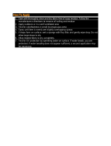
Figure 51-201
Temperature and Humidity Range for Composite Repair Environment
SR20_MM51_1817A
25 27 29 31 33 35 37 39 41 43 45 47 49 51 53 55 57 59 61 63 65 67 69 71 73
55
60
65
70
75
80
85
ACCEPTABLE
CAUTION
TEMPERATURE
(F)
% RELATIVE HUMIDITY
The Acceptable area is the standard storage and bonding environment. The Caution
area indicates storage and bond operations may continue for a limited time under
special procedures while measures are being taken to bring the environment back into
the Acceptable area.
15 Jun 2010

51-20
Page 4
All
EFFECTIVITY:
CIRRUS AIRPLANE MAINTENANCE MANUAL MODEL SR20
01 Jan 2012
2. MAINTENANCE PRACTICES
A. Machining Parameters
Some repairs or installations may require drilling a hole into the composite surface of the airplane. The
following guidelines should be used when drilling into composite structure.
(1) Drills (See Figure 51-202)
(a) Before drilling, verify path of drill bit is clear of any installed components, wire harnesses,
or plumbing. When applicable, use a drill depth stop to avoid drilling deeper than neces-
sary.
(b) When drilling over wires, wire harnesses or electronic equipment, cover area with plastic.
Drill shavings can become lodged in wire bundles and wear through insulation, possibly
causing electrical problems.
(c) Drilling into a composite surface can cause delamination and a possible loss of structural
integrity. To minimize delamination, drill at a high RPM with a very sharp or new drill bit.
(d) Make sure that the hole is correctly aligned to the material surface. Control the drill by use
of a suitable jig or bushed template.
(e) Avoid forcing the drill bit into the material. Apply steady pressure and allow the drill to do
the work. The inner circumference of the drilled hole may be sealed with 5 minute epoxy.
(f) Prevent delamination and fiber damage on the exit face when drilling. Use back-up or
break-out support material where possible.
(2) Drilling Technique
(a) Before drilling, verify path of drill bit is clear of any installed components, wire harnesses,
or plumbing. When applicable, use a drill depth stop to avoid drilling deeper than neces-
sary.
(b) Drilling into a composite surface can cause delamination and a possible loss of structural
integrity. To minimize delamination, drill at a high RPM with a very sharp or new drill bit.
(c) Make sure that the hole is correctly aligned to the material surface. Control the drill by use
of a suitable jig or bushed template.
(d) Avoid forcing the drill bit into the material. Apply steady pressure and allow the drill to do
the work. The inner circumference of the drilled hole may be sealed with 5 minute epoxy.
(e) Prevent delamination and fiber damage on the exit face when drilling. Use back-up or
break-out support material where possible.
(f) Prevent delamination and fiber damage caused by overheating of the drill. Overheating of
laminate is indicated by yellow or brown discoloration around perimeter of hole.
B. Metal Components - Corrosion Removal and Control
All corrosion products must be removed prior to refinishing. If they are not removed, corrosion will
begin again, even though the affected area is refinished.
TBD

CIRRUS AIRPLANE MAINTENANCE MANUAL MODEL SR20
51-20
Page 5
All
EFFECTIVITY:
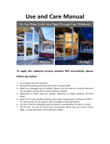
Figure 51-202
Drill Specifications
SR22_MM51_2143
POINT
ANGLE
80° - 135°
HELIX
ANGLE
30°
HELIX
ANGLE
20° - 25°
6°
15°
POINT
ANGLE
120°
AA
AA
CLEARANCE
ANGLE
10°
The helix angle shall be maintained through the insert
to the drill point by carbide tipped drills.
NOTE
CARBIDE OR CARBIDE TIPPED
CUTTER DIAMOND TIPPED
0.04 inch MIN
(1 mm)
Tool
Cutter Material Feed Range
Countersink Carbide
Speed feed: 0.16 - 0.66 ft/min (0.05 - 0.2 m/min)
Drill speed: 800 - 1200 rpm
Diamond tipped
Speed feed: 0.33 - 0.98 ft/min (0.1 - 0.3 m/min)
Drill speed: 1200 - 2400 rpm
Carbide or
diamond tipped
Speed range: 492 - 1640 ft/min (150 - 500 m/min)
Feed range: dependent on cutting depth
Router bit
15 Jun 2010

51-20
Page 6
All
EFFECTIVITY:
CIRRUS AIRPLANE MAINTENANCE MANUAL MODEL SR20
15 Jun 2010
C. Repair Preparation
(1) Surface Protection Removal
This procedure is used only is to remove the paint, primer, and filler partially or completely to the
underlying composite necessary for damage assessment or cosmetic repair. Refer to Procedure
- Repair Surface Preparation for abrasion steps necessary for lamination repair. (Refer to 51-20)
CAUTION: Do not use chemical strippers to remove surface protection. Chemical strippers
may leave a residue and breakdown the epoxy resin.
(a) Acquire necessary tools, equipment, and supplies.
(b) Solvent clean repair area. (Refer to 20-30)
(c) Remove surface protection by abrasion. (Refer to 51-20)
CAUTION: If Expanded Metal Mesh (EMM) is encountered when removing surface pro-
tection, use care not to sand EMM after it becomes shiny. The EMM is very
thin and can easily be sanded through.
1
For paint removal only, lightly sand surface with emery cloth until the layer of primer
is exposed.
2
For primer and paint removal, sand surface until the laminate is exposed. For hand
sanding, use 120- 240 grade emery cloth. If sanding with orbital sander, use 80-120
grade aluminum oxide paper.
(2) Damage Removal
The strength of a composite repair relies upon the integrity of the undamaged and uncontami-
nated supporting material. It is importance that repair surface preparation is carried out to a high
standard to ensure good repair integrity. All damaged structure and other contaminants must be
removed from the composite laminate before repair the can be started.
Glass fiber composites can be removed by hand or through the use of various rotary tools. To
maintain tool life, carbide or diamond cutting edges are recommended.
(a) Acquire necessary tools, equipment, and supplies.
Description P/N or Spec. Supplier Purpose
Vacuum - Any Source Cleaning.
Sanding Pad - Any Source Abrasion.
Emery Cloth
(paint removal only)
120- 240 grade Any Source Abrasion.
Aluminum Oxide Paper
(primer and filler removal)
80-120 grade Any Source Abrasion.
Description P/N or Spec. Supplier Purpose
Paint Brush - Any Source Cleaning.
Vacuum - Any Source Cleaning.
Utility Knife - Any Source Damage removal.
Rotary Tool - Any Source Damage removal.

CIRRUS AIRPLANE MAINTENANCE MANUAL MODEL SR20
51-20
Page 7
All
EFFECTIVITY:
(b) Using brush and vacuum, thoroughly remove any loose contaminants from repair area.
(c) Mark the outline of the extent of the damage and the area of surface protection to be
removed.
(d) Remove surface protection from the damage area. (Refer to 51-20)
CAUTION: Remove the minimum amount of undamaged and uncontaminated support-
ing material. If questions on appropriate damage removal exist, contact Cir-
rus Design for disposition. (Refer to AMM-Intro-)
(e) If performing a Sandwich Structure Replacement:
CAUTION: Minimum overlap is 1.0 inch (2.54 cm). If laminate is 4-ply or greater, maxi-
mum overlap is 2.0 inch (5.08 cm). Laminate less than 2-ply is too thin for
this repair.
1
Using putty knife, remove enough core to expose a border of undamaged inner lam-
inate 0.5 inch (1.3 cm) wide minimum for each ply of the repair. For example: A 3-ply
damaged laminate would be trimmed back 1.5 inches (3.8 cm) minimum.
2
Sand off residual core from the surface of the inner laminate. Be careful not to cause
separation between core and inner laminate during this operation.
3
Inspect for separation of the inner laminate from the core. Continue to sand back
until all separated laminate is removed.
(f) If applicable, Remove EMM:
CAUTION: Exercise great care while removing EMM. Abrasive materials can quickly
cut through EMM, damaging underlying fiberglass plies.
Avoid operating the removal tool at high speeds, excessively tilting the tool,
or leaving the tool in the same area for more than a few seconds. Use
slower tool speeds combined with a flatter edgeless operation to cause the
EMM to disbond from the laminate surface without damaging underlying
fiberglass plies. Move the tool frequently to visually ensure no damage
occurs during the removal process.
1
Using rotary tool or orbital sander, gently abrade the EMM surface.
2
As outer resin coat is abraded, the EMM with become polished and begin to blister.
3
Once blistered, remove EMM with a utility knife.
(g) Remove damaged material using a utility knife, rotary tool, or die grinder with depth
gauges installed when applicable.
(3) Determining Ply Count
Ply count refers to the number of plies in a given thickness of unfinished laminate. To determine
ply count, measure the thickness of undamaged, unpainted laminate in a area adjacent to the
repair area then verify by comparing the measurement to the ply lay-up tables in the Airframe
Zone Diagrams. (Refer to 51-00)
90° Die Grinder - Any Source Damage removal.
Orbital Sander - Any Source Abrasion.
Description P/N or Spec. Supplier Purpose
01 May 2012

51-20
Page 8
All
EFFECTIVITY:
CIRRUS AIRPLANE MAINTENANCE MANUAL MODEL SR20
01 May 2012
(a) Acquire necessary tools, equipment, and supplies.
(b) Remove surface protection from section of repair area. (Refer to 51-20)
(c) Solvent clean repair area. (Refer to 20-30)
Note: The thickness of one ply is 0.008 - 0.010 inch (0.203 - 0.254 mm). To verify,
or if no value is found in the ply lay-up tables, determine ply count by divid-
ing measured laminate thickness by 0.009 inch (0.229 mm).
(d) Using a micrometer, measure the thickness of undamaged, unpainted laminate in an area
adjacent to the repair area.
(e) For partially penetrated damage:
1
Using a micrometer, measure the thickness of damaged laminate in the repair area.
2
Determine number of damaged plies by subtracting thickness of damaged laminate
from undamaged laminate.
(f) Reference the ply lay-up tables in the Airframe Zone Diagrams, to verify the number of
plies. (Refer to 51-00)
(4) Determining Ply Orientation (See Figure 51-203)
The glass-fabric used for repair on this airplane is Hexcel 7781. This fabric is considered a bal-
anced cloth because approximately 50% of the fibers run parallel to warp, and approximately
50% run perpendicular to warp. Fibers that run parallel to the selvage edge have a fiber orienta-
tion of 0°. The warp clock, located on each of the Airframe Zone Diagrams, is used to determine
ply orientation by indicating how the – and + angled plies are defined. The warp clock is always
viewed from the outside of the fuselage, or the tool surface, looking in. (Refer to 51-00)
Generally, the +0° axis is parallel to the ground and/or centerline of the fuselage. For example,
the main spar runs perpendicular to the 0° axis. The 90º axis is always perpendicular to the 0º
axis. The 45º axis is located by moving clockwise from 0º to 90º.
Once ply orientation is determined, it is permissible to mark the warp axis on the repair fabric
with a permanent marker.
Description P/N or Spec. Supplier Purpose
Micrometer - Any Source Measurement.

CIRRUS AIRPLANE MAINTENANCE MANUAL MODEL SR20
51-20
Page 9
All
EFFECTIVITY:
Figure 51-203
Determining Ply Orientation
4
5
°
0
°
-
4
5
°
9
0
°
SPECIAL BALANCED FIBERGLASS TYPE 7781
FABRIC BOLT
SR20_MM51_1190A
SELVAGE EDGE
FILL
WARP
(0° AXIS)
WARP CLOCK
TOOL SURFACE
15 Jun 2010

51-20
Page 10
All
EFFECTIVITY:
CIRRUS AIRPLANE MAINTENANCE MANUAL MODEL SR20
01 May 2012
(5) Repair Surface Preparation
Generally, hand-sanding or a orbital type sander are the preferred methods of repair surface
preparation. Care must be exercised not to apply excessive pressure on the sander, which could
tear into the laminate. The grade of sanding paper is to be chosen to suit and give a smooth fin-
ish. Do not use grinders, air files, or other single-action tools as they tend to intensify pressure
and will rapidly remove paint and damage the underlying laminate.
To facilitate proper sanding depth and surface coverage, marking the composite repair area with
a permanent maker to act as a depth tracer is recommended.
Remove dust and observe laminate surface frequently during the sanding procedure. If fiber
damage is apparent, stop sanding and repair the damaged area. When preparing peel ply sur-
faces, sand surface until the impression left from the peel ply is no longer visible. When prepar-
ing surfaces where no peel ply was present, such as barrier film, sand surface until no gloss is
visible. Replace or clean sandpaper often.
The repair surface must be free of EMM in an area equal to the size and shape of the largest
repair ply plus 0.5".
CAUTION: Do not use chemical strippers to remove surface protection. Chemical strippers
may leave a residue and breakdown the epoxy resin.
Note: To prevent possible re-contamination of the repair area, the repair must be done
immediately following repair surface preparation.
(a) Acquire necessary tools, equipment, and supplies.
(b) Remove damage from repair area. (Refer to 51-20)
(c) Determine warp axis and draw 0° reference line so it intersects the center of the damage.
This line will later be used for positioning repair plies.
(d) Mask off area surrounding repair with masking tape and paper. This area should include
the intended faying surface area plus at least 2 inches (50 mm).
(e) If applicable, install backing plate. (Refer to 51-20)
(f) For secondary bond damage, sand repair area:
Description P/N or Spec. Supplier Purpose
Tape - Any Source Masking.
Paper - Any Source Masking.
Vacuum - Any Source Cleaning.
Paint Brush - Any Source Cleaning.
Permanent Marker (Refer to 51-30) (Refer to 51-30) Depth tracer.
Sanding Pad - Any Source Abrasion.
Aluminum Oxide Paper
(hand sanding)
60 to 80 grade Any Source Abrasion.
Orbital Sander - Any Source Abrasion.
Aluminum Oxide Paper
(orbital sander)
120 to 180 grade Any Source Abrasion.

CIRRUS AIRPLANE MAINTENANCE MANUAL MODEL SR20
51-20
Page 11
All
EFFECTIVITY:
1 Define sanding area with marker and fill area with a cross-hatch of other random
pattern. Allow a short drying period before sanding until depth tracer is dry to the
touch.
2
Sand repair area in a random pattern until depth tracer is gone. Frequently clean
repair surface of contaminants using vacuum and paint brush.
(g) For sandwich penetration damage requiring foam core replacement, replace foam core.
(Refer to 51-20)
(h) For sandwich penetration damage requiring sandwich structure replacement, replace sec-
tion. (Refer to 51-20)
(i) For solid laminate and composite sandwich structure, sand repair area:
1
Define sanding area with marker.
Note: Laminate that is 2-ply or less does not require a taper.
2
Sand repair area in a random pattern so that face of damaged laminate tapers to a
1:50 ratio (i.e., taper length is 50 times the thickness of the laminate). Frequently
clean repair surface of contaminants using vacuum and paint brush.
(j) If applicable, prepare Expanded Metal Mesh (EMM) surface:
CAUTION: Do not sand EMM after it becomes shiny. EMM is very thin and can easily
be sanded through.
1
At perimeter of EMM, use 80 grade sand paper or finer to lightly sand existing EMM
until shiny.
2
Prepare perimeter of existing EMM so that replacement EMM overlaps existing
EMM by at least 0.2 inch (5.0 mm). (Refer to 51-20)
(k) Solvent clean repair area. (Refer to 20-30)
(l) Dry repair area. (Refer to 51-20)
(6) Repair Ply Construction (See Figure 51-204)
After the extent of damage is determined, repair plies may be made. A template is used to assist
in cutting the correct shape and size of glass-fabric. Release film or clear plastic sheet may be
used for template construction.
Once the template is made, glass-fiber cloth can be cut. Use clean, sharp scissors or a razor
knife. Dull tools will catch and pull fibers, distorting the fabric. To reduce the likelihood of stress
risers developing post repair, round the edges of the repair plies when cutting. Exercise caution
when cutting and handling the glass-fiber cloth to maintain fiber orientation. Do not handle glass-
fabric materials with bare hands.
When three or less repair plies are required, a 1.0 inch (2.5 cm) minimum overlap of all repair
plies is required. When more than three repair plies are required, a 0.5 inch (1.3 cm) minimum
initial overlap is required along with each subsequent ply extending 0.5 inch (1.3 cm) minimum
beyond the previous plies.
It is difficult to determine the fiber orientation of a piece of cloth once the selvage edge has been
removed. If the selvage edge is unknown the fabric must be discarded. When cutting plies, hold
template against the fabric as this will reduce the chance of distorting the material. Ensure tem-
plate is positioned in the proper orientation. The template should be kept with the repair ply.
To determine number of repair plies to prepare, reference the ply lay-up tables in the Airframe
Zone Diagrams. (Refer to 51-00) If no repair ply quantity is shown, always prepare and install
twice as many repair plies as original lay-up in order to ensure that original strength is achieved.
01 May 2012

51-20
Page 12
All
EFFECTIVITY:
CIRRUS AIRPLANE MAINTENANCE MANUAL MODEL SR20
01 May 2012
(a) Acquire necessary tools, equipment, and supplies.
(b) Prepare repair surface. (Refer to 51-20)
(c) Construct template as follows:
1
Referencing ply lay-up tables in the Airframe Zone Diagrams, determine number of
repair plies necessary for repair. (Refer to 51-00)
2
Tape plastic sheet over damaged area.
3
Center, offset, and draw perimeter line on plastic 1.0 inch (2.5 cm) from the inside
edge of damage. This is the dimension of the first and smallest repair ply.
4
Center, offset, and draw another perimeter line 0.5 - 1.0 inch (1.3 - 2.5 cm) from the
existing line. This is the dimension of the next repair ply.
5
Repeat above steps for each subsequent repair ply.
6
Label template boxes with correct ply orientation for later reference. (Refer to 51-20)
(d) Cut repair plies as follows:
1
Place fabric on a contaminate-free cutting surface.
2
Position and orient template on fabric.
3
Cut fabric to the same dimension as template.
Description P/N or Spec. Supplier Purpose
Masking Tape - Any Source Template fabrication.
Plastic Sheet - Any Source Template fabrication.
Permanent Marker (Refer to 51-30) (Refer to 51-30) Template fabrication.
Scissors - Any Source Cutting.
Glass Fiber Cloth (Refer to 51-30) (Refer to 51-30) Ply construction.

CIRRUS AIRPLANE MAINTENANCE MANUAL MODEL SR20
51-20
Page 13
All
EFFECTIVITY:
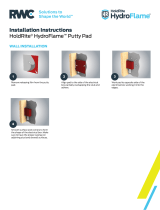
Figure 51-204
Repair Ply Construction
DAMAGED
LAMINATE
SR20_MM51_2118
9
0
°
-
4
5
°
0
°
4
5
°
1.0 inch
(2.5 cm)
1.0 inch
(2.5 cm)
PLASTIC SHEET
Reference ply lay-up tables on the
Airframe Zone Diagrams to determine
ply count. If no repair ply quantity is
indicated, install twice as many plies
as original lay-up.
NOTE
+45°
+45°
-45°
-45°
LEFT WING TOP VIEW SHOWN
RIGHT WING TOP OPPOSITE
LEFT WING BOTTOM VIEW SHOWN
RIGHT WING BOTTOM OPPOSITE
-
6
6
-
12
2
-
7
-
0.375 (9.525)
-
0.375 (9.525)
-
2
-
5
-
5
4
3
2
1
Ply Only
Quantity
Inner Ply
Quantity
Core Material
Thickness
inches (mm)
Outer Ply
Quantity
Reference
Number
-
3
0.375 (9.525)
26
5
---
7
4
---
8
-
4
0.375 (9.525)
29
8
---
10
8
---
11
6
---
12
-
3
0.375 (9.525)
2
13
-
3.0 to 1.0
Repair Plies
To Original
Lay-Up
4
-
4
-
2
-
-
-
-
2
-
22
21
20
19
18
Ply Only
Quantity
Inner Ply
Quantity
Core Material
Thickness
inches (mm)
Outer Ply
Quantity
Reference
Number
6
---
23
10
---
24
-
64
25
-
62
26
-
42
27
-
44
28
-
24
29
8
---
30
1.5 to 1.0
Repair Plies
To Original
Lay-Up
-
4
0.375 (9.525)
2
14
6
---
31
5
---
15
7
---
32
5
---
16
-
4
0.375 (9.525)
3
33
-
2
0.375 (9.525)
2
17
9
---
34
3.0 to 1.0
2.5 to 1.0
3.5 to 1.0
2.0 to 1.0
2.0 to 1.0
2.0 to 1.0
3.0 to 1.0
2.0 to 1.0
3.0 to 1.0
2.0 to 1.0
2.5 to 1.0
3.5 to 1.0
3.5 to 1.0
3.0 to 1.0
2.0 to 1.0
2.5 to 1.0
2.5 to 1.0
3.5 to 1.0
4.0 to 1.0
2.5 to 1.0
2.5 to 1.0
2.0 to 1.0
1.5 to 1.0
2.0 to 1.0
1.5 to 1.0
1.5 to 1.0
2.0 to 1.0
2.0 to 1.0
2.5 to 1.0
-
1
0.375 (9.525)
2
2.5 to 1.0
3
---
2.5 to 1.0
---
1
10
3
2
4
8
9
6
7
11
12
15
14
17
18
7
16
13
12
12
18
7
13
23
19
20
4
8
11
5
27
26
29
28
23
22
28
29
2726
25
24
30
31
32
12
19
28
33
34
8
17
25
5
25
18
WS
20
WS
40
WS
60
WS
80
WS
100
WS
120
WS
140
WS
160
WS
180
WS
200
Lightning Protection
Bond Line
No Repair Area on
Lightning Protection
No Repair Area
LEGEND
WS
200
WS
180
WS
160
WS
140
WS
120
WS
100
WS
80
WS
60
WS
40
WS
20
0.375 (9.525)
0.375 (9.525)
0.375 (9.525)
0.375 (9.525)
0.375 (9.525)
0.375 (9.525)
45°
0°
-45°
90°
45°
0°
-45°
90°
When three or less repair plies are
required, a 1.0 inch (2.5 cm) (minimum)
overlap of all repair plies is required.
When more than three repair plies are
required, a 0.5 inch (1.3 cm) (minimum)
initial overlap is required along with each
subsequent ply extending 0.5 inch (1.3 cm)
(minimum) beyond the previous plies.
15 Jun 2010

51-20
Page 14
All
EFFECTIVITY:
CIRRUS AIRPLANE MAINTENANCE MANUAL MODEL SR20
15 Jun 2010
(7) Backing Plate Construction
Backing plates are used to repair composites that have been punctured by serving to bridge the
hole left during the damage event. A backing plate can be bonded to the inner or outer surface of
the repair area and are constructed from the same material used for repairing the laminate. The
number of plies required is dependent on the size of the hole. To ensure finished backing plate
does not warp, lay backing plate plies up in opposing orientation. Minor warping is not cause for
concern as the plates are generally thin and flexible and can be forced to the correct contour
when necessary.
(a) Acquire necessary tools, equipment, and supplies.
Note: Final repair surface sanding must be done with backing plate installed.
(b) Remove surface protection. (Refer to 51-20)
(c) Determine extent of damage. (Refer to 51-10)
(d) To facilitate separation of backing plate from lay-up surface, cover repair area with release
film. Remove all wrinkles.
(e) Offset and draw perimeter line on release film 1.0 inch (2.5 cm) from the inside edge of
hole. This is the dimension of the backing plate.
(f) Cut backing plate plies to the same dimension as perimeter line.
(g) Mix non-structural resin. (Refer to 51-30)
(h) Construct backing plate using Laminating by Transfer method. (Refer to 51-20)
(8) Water Break Test
CAUTION: The following procedure should only be performed at the disposition of Cirrus
Design or if specifically referenced by repair.
A water break test will show when the repair area surface has been correctly prepared and will
ensures maximum bond strength.
(a) Acquire necessary tools, equipment, and supplies.
(b) Solvent clean repair area. (Refer to 20-30)
(c) Dry repair area. (Refer to 51-20)
Description P/N or Spec. Supplier Purpose
Release Film (Refer to 51-30) (Refer to 51-30) Backing plate construction.
Peel Ply (Refer to 51-30) (Refer to 51-30) Backing plate construction.
Non-Structural Resin
Repair System
(Refer to 51-30) (Refer to 51-30) Backing plate construction.
Glass Fiber Cloth (Refer to 51-30) (Refer to 51-30) Backing plate construction.
Description P/N or Spec. Supplier Purpose
Cotton Cloth (clean, lint free) - Any Source Cleaning.
De-Mineralized Water - Any Source Cleaning.

CIRRUS AIRPLANE MAINTENANCE MANUAL MODEL SR20
51-20
Page 15
All
EFFECTIVITY:
Note: When there is no risk of getting water trapped in open sandwich or the
structure, a thin layer of de-mineralized water may be sprayed on the sur-
face.
(d) Perform Water Break Inspection.
1
Soak cloth with de-mineralized water and move cloth across repair surface to apply
a thin layer of water to the surface.
2
Inspect the wetted surface. When water forms a complete thin layer over whole of
the surface, and surface tension of the water does not cause water to form into
drops or beads, surface is clean.
3
Leave the water on the surface for 30 seconds. The water must remain as a com-
plete film over the surface for this period.
4
If the water separates or forms drops or beads within the 30 seconds, repeat solvent
cleaning procedure. (Refer to 20-30)
(e) Repeat Procedure - Water Break Test until no contamination is noted on drying cloth.
(Refer to 51-20)
(f) Dry repair area. (Refer to 51-20)
(9) Drying Composite Structure (See Figure 51-205)
Because composites can trap water during service or repair, it is essential to thoroughly dry the
structure before a repair is performed. Trapped moisture can cause composite structure dis-
bonding or delamination both inside and outside the repair area due to due steam pressure gen-
erated during the cure cycle.
Since there is no practical method for quantifying the moisture content of a composite structure,
the structure should always be considered as saturated. Even when the composite structure is
visually dry it is necessary to perform a final drying before repairing. Visible liquid should first be
removed using absorbtion, vacuuming, and/or compressed air. Radiant heat or hot air may be
used as the final drying technique.
CAUTION: Liquids that do not dry completely or leave a residue (jet fuel or hydraulic fluid for
example), must be cleaned and dried by some other method or the contaminated
part replaced entirely. Call Cirrus Design for disposition. (Refer to AMM-Intro-)
(a) Dry any visible liquid as follows:
1
Acquire necessary tools, equipment, and supplies.
2
Solvent clean repair area. (Refer to 20-30)
3
Absorb visible liquid using cotton cloth.
CAUTION: Do not allow flammable liquids or gases to enter the vacuum pump.
Ensure a vacuum system is approved for flammable liquid removal is
used.
4
If necessary, use vacuum to remove liquid from affected areas.
Description P/N or Spec. Supplier Purpose
Cotton Cloth (clean, lint free) - Any Source Liquid removal.
Vacuum - Any Source Liquid removal.
Dry Compressed Air - Any Source Liquid removal.
15 Jun 2010

51-20
Page 16
All
EFFECTIVITY:
CIRRUS AIRPLANE MAINTENANCE MANUAL MODEL SR20
15 Jun 2010
CAUTION: Care should be taken not to force water further into the structure or to
damage the structure with excessive pressure. Do not exceed gage
pressure of 30 psi.
5
If necessary, use dry compressed air to remove liquid from affected areas.
(b) Final dry repair area using the following Radiant Heat or Hot Air methods.
(c) Drying Using Radiant Heat (See Figure 51-205)
1
Acquire necessary tools, equipment, and supplies.
2
Remove visible liquid.
3
Solvent clean repair area. (Refer to 20-30)
4
Install thermocouple(s) at center of heated area.
5
Connect electronic temperature control unit(s) and thermocouple(s).
CAUTION: Do not cause damage to the structure by over-heating. Ensure heat
lamps are properly calibrated. Do not exceed part temperature of
195° F (91° C) and do not allow air temperature to exceed 200° F (93°
C).
6
Apply required heat to structure ensuring temperature is raised at a rate not greater
than 1.0° - 5.0° F (0.6° - 2.8° C) per minute.
7
Monitor temperature and dry structure for two hours.
8
Remove heat from structure ensuring temperature is lowered at a rate not greater
than 1.0° - 15.0° F (0.6° - 8.4° C) per minute.
9
Let structure cool to room temperature before beginning repair.
(d) Drying Using Hot Air (See Figure 51-205)
To supply heated air, use a hot air dryer with temperature control, or optionally, a dryer
system driven by thermocouples. Do not use hot air dryers without some method of tem-
perature monitoring in place as temperatures achieved may be too high.
1
Acquire necessary tools, equipment, and supplies.
Description P/N or Spec. Supplier Purpose
Cotton Cloth
(clean, lint free)
- Any Source Liquid removal.
250 W Heat Lamp(s) - Any Source Liquid removal.
Electronic Temperature
Control Unit
A419ABG-3C Johnson Controls, Inc.
Milwaukee, WI 53201
414-524-4000
Temperature
control.
Infrared Thermometer MiniTemp MT4
w/ laser point
Raytek Corporation
Santa Cruz, CA 95061
800-866-5478
Temperature
measurement.
Description P/N or Spec. Supplier Purpose
Cotton Cloth
(clean, lint free)
- Any Source Liquid removal.

CIRRUS AIRPLANE MAINTENANCE MANUAL MODEL SR20
51-20
Page 17
All
EFFECTIVITY:
2 Remove visible liquid.
3
Solvent clean repair area. (Refer to 20-30)
4
To maintain a constant distance between dryer and structure, place hot air dryer in
holding fixture.
5
Install thermocouple(s) at center of air flow area.
6
Connect monitor and thermocouple(s).
CAUTION: Do not cause damage to the structure by over-heating. Ensure dryers
are no closer than 10 inches (25 cm) from structure. Do not exceed
part temperature of 195° F (91° C).
7
Apply required heat to structure ensuring temperature is raised at a rate not greater
than 1.0° - 5.0° F (0.6° - 2.8° C) per minute.
8
Periodically monitor temperature using infrared thermometer and dry structure for
two hours.
9
Remove heat from structure ensuring temperature is lowered at a rate not greater
than 1.0° - 15.0° F (0.6° - 8.4° C) per minute.
10
Let structure cool to room temperature before beginning repair.
Hot Air Dryer
(1500 - 1875 Watt)
- Any Source Liquid removal.
Infrared Thermometer MiniTemp MT4
w/ laser point
Raytek Corporation
Santa Cruz, CA 95061
800-866-5478
Temperature
measurement.
Description P/N or Spec. Supplier Purpose
15 Jun 2010

51-20
Page 18
All
EFFECTIVITY:
CIRRUS AIRPLANE MAINTENANCE MANUAL MODEL SR20
15 Jun 2010
Figure 51-205
Typical Drying Methods
SR20_MM51_2116
X
H
T
200
(94)
170
(77)
150
(66)
130
(54)
6 (152)
7 (178)
8 (203)
9 (228)
10 (254)
11 (280)
12 (305)
13 (330)
14 (355)
15 (380)
5 (127)
250W
HEAT LAMP
HEIGHT
inch (mm)
TEMPERATURE °F (°C)
10 inches
(254 mm)
H
H
X
PROBE
PROBE
1500W - 1875W
HOT AIR
DRYER
250W
HEAT LAMP
250W
HEAT LAMP
GRAPH 1
HOT AIR DRYER METHOD
METHOD 1:
Construct Graph 1 to show the temperature at
the center of the heated area as a function of
the distance between the heat lamp and surface.
NOTE
METHOD 2:
Use electronic temperature control to maintain
constant heat.
RADIANT HEAT METHODS
Periodically check temperature with infrared
thermometer.
ELECTRONIC
TEMPERATURE
CONTROL
INFRARED
THERMOMETER
INFRARED
THERMOMETER

CIRRUS AIRPLANE MAINTENANCE MANUAL MODEL SR20
51-20
Page 19
All
EFFECTIVITY:
D. Repair Processes
(1) Amine Blush Detection and Removal
CAUTION: Special preparation may be required for surfaces repaired with epoxies using
polyamine hardeners such as Epon 862 or PTM&W ES6292. During the cure pro-
cess, amine blush, a thin, waxy film may form on the surface of the epoxy. This
film can greatly impair the strength of a repair bond.
Amine blush is a thin, waxy, soap-like film that forms on the surface of mixed epoxy resins that
use aliphatic amines - such as Epon 862 or PTM&W ES6292 - in the hardener. The blush film
begins to form on the surface of the adhesive immediately after being applied.
During a wet repair, in order to achieve a successful bond, the blush film must be broken when
the faying surfaces are pressed together. For this to happen, the adhesive applied to both faying
surfaces must be thick enough to be disrupted or "squish out".
Additional methods of eliminating amine blush are available; during the repair process; always
applying peel ply over the surface of the epoxy which will removed the film when the peel ply is
peeled from the cured epoxy, or remove the blush using a water wash.
To remove the blush using the water wash method, wash the surface with clean water and an
abrasive pad. Dry the surface with plain white paper towels to remove the dissolved blush before
it dries on the surface. After washing with the abrasive pad, the surface should appear dull. Sand
any remaining glossy areas.
(2) MGS L418-Based Structural Adhesive Application
Application of structural adhesive is required for secondary bond repairs where the technician
must bond two pre-cured components together.
Note: Nominal bondline thickness for structural repair is 0.060 +0.020/-0.055 inch
(0.152 +0.051/-0.140 cm) unless otherwise noted.
(a) Acquire necessary tools, equipment, and supplies.
(b) Prepare repair surface as necessary. (Refer to 51-20)
(c) Pre-fit faying surfaces of parts to ensure the bond fixture used will bring the bonded sur-
faces into an allowable tolerance during adhesive curing.
(d) Mix structural adhesive. (Refer to 51-30)
(e) Prior to applying the bulk of adhesive, wet the faying surface by working a thin layer of
adhesive into the laminate substrate.
(f) Apply a sufficient quantity of adhesive, determining the actual bond gap and width, so that
the joint will be completely filled over the faying surface width.
Description P/N or Spec. Supplier Purpose
Wooden or Plastic Spatula - Any Source Apply adhesive.
Cartridge or Extrusion Gun - Any Source Apply adhesive.
Bond Fixture (as necessary) - Any Source Bonding.
Clamps (as necessary) - Any Source Bonding.
MGS L418-Based Structural
Adhesive
(Refer to 51-
30)
(Refer to 51-30) Core replacement.
15 Jun 2010

51-20
Page 20
All
EFFECTIVITY:
CIRRUS AIRPLANE MAINTENANCE MANUAL MODEL SR20
01 Jan 2012
Note: The adhesive bead should have a high point near the center of the bead to
avoid entrapped air. When more than one bead is required, apply immedi-
ately adjacent to the prior bead to form one large bead.
(g) Apply a bead of adhesive down the center of the bond width, approximately 0.13 - 0.25
inch (3.18 - 6.35 mm) bead for each 1.0 inch (25.4 mm) of bond width.
Note: Avoid applying, removing, and re-applying clamping pressure, as this will
cause air to become entrapped in the bond gap.
(h) Secure parts in bond fixture, ensuring that pressure is applied uniformly.
(i) Check edge of bondline for excess adhesive. Remove excess adhesive with cloth damp-
ened with isopropyl alcohol.
(j) Cure bond. (Refer to 51-20)
(3) PTM&W ES6292-Based Structural Adhesive Application (See Figure 51-206)
Application of structural adhesive is required for secondary bond repairs where the technician
must bond two pre-cured components together.
CAUTION: PTM&W ES6292, when allowed to sit creates amine blush. This surface layer
inhibits proper bonding and care must be taken to avoid it. (Refer to 51-20)
Proper application of PTM&W ES6292 adhesive is critical to obtaining full bond
strength. Application procedures differ from other structural adhesive applications
and should be fully understood before mixing.
Note: Nominal bondline thickness for structural repair is 0.060 +0.020/-0.055 inch
(0.152 +0.051/-0.140 cm) unless otherwise noted.
(a) Acquire necessary tools, equipment, and supplies.
(b) Prepare repair surface as necessary. (Refer to 51-20)
(c) Pre-fit faying surfaces of parts to ensure the bond fixture used will bring the bonded sur-
faces into an allowable tolerance during adhesive curing.
Note: PTM&W ES6292 A/B Paste Adhesive has a pot-life at 68
o
F of 45 minutes.
High ambient temperatures will shorten pot-life. An 18
o
F increase will cut
pot-life to 22 minutes. Relative humidity above 65% accelerates reaction
and also shortens pot-life. Working-life of 35 minutes is similarly affected.
(d) Mix structural adhesive. (Refer to 51-30)
(e) On first surface of the repair, apply adhesive using one of the following methods.
Description P/N or Spec. Supplier Purpose
Trowel, 1/4” V-notch - Any Source Spread adhesive.
Cartridge or Extrusion Gun - Any Source Apply adhesive.
Bond Fixture (as necessary) - Any Source Bonding.
Clamps (as necessary) - Any Source Bonding.
PTM&W ES6292-Based
Structural Adhesive
(Refer to 51-30) (Refer to 51-30) Bond Repairs.
/