Page is loading ...

PanelView 5510 Terminals
Catalog Numbers 2715P-B7CD, 2715P-B7CD-B, 2715P-T7CD, 2715P-T7CD-B, 2715P-T7WD, 2715P-T7WD-B,
2715P-T9WD, 2715P-T9WD-B, 2715P-B10CD, 2715P-B10CD-B, 2715P-T10CD, 2715P-T10CD-B, 2715P-T12WD,
2715P-T12WD-B, 2715P-B15CD, 2715P-B15CD-B, 2715P-T15CD, 2715P-T15CD-B, 2715P-T19CD, 2715P-T19CD-B
User Manual
Original Instructions

Important User Information
Read this document and the documents listed in the additional resources section about installation, configuration, and
operation of this equipment before you install, configure, operate, or maintain this product. Users are required to
familiarize themselves with installation and wiring instructions in addition to requirements of all applicable codes, laws,
and standards.
Activities including installation, adjustments, putting into service, use, assembly, disassembly, and maintenance are
required to be carried out by suitably trained personnel in accordance with applicable code of practice.
If this equipment is used in a manner not specified by the manufacturer, the protection provided by the equipment may
be impaired.
In no event will Rockwell Automation, Inc. be responsible or liable for indirect or consequential damages resulting from
the use or application of this equipment.
The examples and diagrams in this manual are included solely for illustrative purposes. Because of the many variables and
requirements associated with any particular installation, Rockwell Automation, Inc. cannot assume responsibility or
liability for actual use based on the examples and diagrams.
No patent liability is assumed by Rockwell Automation, Inc. with respect to use of information, circuits, equipment, or
software described in this manual.
Reproduction of the contents of this manual, in whole or in part, without written permission of Rockwell Automation,
Inc., is prohibited.
Throughout this manual, when necessary, we use notes to make you aware of safety considerations.
Labels may also be on or inside the equipment to provide specific precautions.
WARNING: Identifies information about practices or circumstances that can cause an explosion in a hazardous
environment, which may lead to personal injury or death, property damage, or economic loss.
ATTENTION: Identifies information about practices or circumstances that can lead to personal injury or death, property
damage, or economic loss. Attentions help you identify a hazard, avoid a hazard, and recognize the consequence.
IMPORTANT Identifies information that is critical for successful application and understanding of the product.
SHOCK HAZARD: Labels may be on or inside the equipment, for example, a drive or motor, to alert people that dangerous
voltage may be present.
BURN HAZARD: Labels may be on or inside the equipment, for example, a drive or motor, to alert people that surfaces may
reach dangerous temperatures.
ARC FLASH HAZARD: Labels may be on or inside the equipment, for example, a motor control center, to alert people to
potential Arc Flash. Arc Flash will cause severe injury or death. Wear proper Personal Protective Equipment (PPE). Follow ALL
Regulatory requirements for safe work practices and for Personal Protective Equipment (PPE).

Rockwell Automation Publication 2715P-UM001C-EN-P - March 2019 3
Table of Contents
Preface
Summary of Changes . . . . . . . . . . . . . . . . . . . . . . . . . . . . . . . . . . . . . . . . . . . 7
Package Contents . . . . . . . . . . . . . . . . . . . . . . . . . . . . . . . . . . . . . . . . . . . . . . 7
Request Corresponding Source for Open Source Packages . . . . . . . . . 8
Product Firmware and Release Notes . . . . . . . . . . . . . . . . . . . . . . . . . . . . 8
Additional Resources . . . . . . . . . . . . . . . . . . . . . . . . . . . . . . . . . . . . . . . . . . . 9
Chapter 1
Overview About the PanelView 5510 Terminals . . . . . . . . . . . . . . . . . . . . . . . . . . 11
Hardware Features . . . . . . . . . . . . . . . . . . . . . . . . . . . . . . . . . . . . . . . . . . . . 12
Operator Control . . . . . . . . . . . . . . . . . . . . . . . . . . . . . . . . . . . . . . . . . . . . . 12
Touch Gestures . . . . . . . . . . . . . . . . . . . . . . . . . . . . . . . . . . . . . . . . . . . . . . . 14
Studio 5000 Environment . . . . . . . . . . . . . . . . . . . . . . . . . . . . . . . . . . . . . 14
EtherNet/IP Communication. . . . . . . . . . . . . . . . . . . . . . . . . . . . . . . . . . 16
Typical Configuration . . . . . . . . . . . . . . . . . . . . . . . . . . . . . . . . . . . . . . . . . 16
Catalog Number Explanation . . . . . . . . . . . . . . . . . . . . . . . . . . . . . . . . . . 16
Product Selection . . . . . . . . . . . . . . . . . . . . . . . . . . . . . . . . . . . . . . . . . . . . . 17
Accessories . . . . . . . . . . . . . . . . . . . . . . . . . . . . . . . . . . . . . . . . . . . . . . . . . . . 17
Ethernet Cables . . . . . . . . . . . . . . . . . . . . . . . . . . . . . . . . . . . . . . . . . . . . . . . 18
Chapter 2
Install the PanelView 5510
Terminal
Installation Precautions. . . . . . . . . . . . . . . . . . . . . . . . . . . . . . . . . . . . . . . . 20
Environment and Enclosure Information. . . . . . . . . . . . . . . . . . . . 20
Wiring and Safety Guidelines. . . . . . . . . . . . . . . . . . . . . . . . . . . . . . . 21
Outdoor Installation Recommendations . . . . . . . . . . . . . . . . . . . . 21
North American Hazardous Locations. . . . . . . . . . . . . . . . . . . . . . . . . . 23
Required Circuit Port Parameters for USB Peripheral Devices. 24
Mounting Considerations . . . . . . . . . . . . . . . . . . . . . . . . . . . . . . . . . . . . . 25
Mounting Clearances. . . . . . . . . . . . . . . . . . . . . . . . . . . . . . . . . . . . . . . . . . 25
Panel Guidelines . . . . . . . . . . . . . . . . . . . . . . . . . . . . . . . . . . . . . . . . . . . . . . 26
Panel Cutout Dimensions . . . . . . . . . . . . . . . . . . . . . . . . . . . . . . . . . . . . . 26
Product Dimensions. . . . . . . . . . . . . . . . . . . . . . . . . . . . . . . . . . . . . . . . . . . 27
Prepare for Panel Mounting. . . . . . . . . . . . . . . . . . . . . . . . . . . . . . . . . . . . 28
Mount the Terminal in a Panel . . . . . . . . . . . . . . . . . . . . . . . . . . . . . . . . . 31
Remove and Replace the DC Power Terminal Block . . . . . . . . . . . . . 34
Connect to DC Power. . . . . . . . . . . . . . . . . . . . . . . . . . . . . . . . . . . . . . . . . 35
Connect to a Network. . . . . . . . . . . . . . . . . . . . . . . . . . . . . . . . . . . . . . . . . 36
Ethernet Ports . . . . . . . . . . . . . . . . . . . . . . . . . . . . . . . . . . . . . . . . . . . . 36
Device Level Ring Network Topology. . . . . . . . . . . . . . . . . . . . . . . 37
Linear Network Topology. . . . . . . . . . . . . . . . . . . . . . . . . . . . . . . . . . 38
Star Network Topology . . . . . . . . . . . . . . . . . . . . . . . . . . . . . . . . . . . . 39
Initial Startup. . . . . . . . . . . . . . . . . . . . . . . . . . . . . . . . . . . . . . . . . . . . . . . . . 39
Update the Firmware Before You Use the Terminal . . . . . . . . . . 40

4 Rockwell Automation Publication 2715P-UM001C-EN-P - March 2019
Table of Contents
Chapter 3
Configure Terminal Settings Runtime Environment. . . . . . . . . . . . . . . . . . . . . . . . . . . . . . . . . . . . . . . . . 43
Entering Data Using Virtual Keyboards . . . . . . . . . . . . . . . . . . . . . . . . . 45
Log On to the Terminal . . . . . . . . . . . . . . . . . . . . . . . . . . . . . . . . . . . . . . . 47
Log Off of the Terminal . . . . . . . . . . . . . . . . . . . . . . . . . . . . . . . . . . . . . . . 48
Settings Menu . . . . . . . . . . . . . . . . . . . . . . . . . . . . . . . . . . . . . . . . . . . . . . . . 48
Configure the IP Address of the Terminal. . . . . . . . . . . . . . . . . . . . . . . 50
Use DHCP to Assign an IP Address For the Terminal. . . . . . . . 50
Assign a Static IP Address For the Terminal . . . . . . . . . . . . . . . . . 51
Configure a DNS Address For the Terminal. . . . . . . . . . . . . . . . . . . . . 52
Configure the Ethernet Ports . . . . . . . . . . . . . . . . . . . . . . . . . . . . . . . . . . 53
View the Network Diagnostics . . . . . . . . . . . . . . . . . . . . . . . . . . . . . . . . . 54
Export a Data Log. . . . . . . . . . . . . . . . . . . . . . . . . . . . . . . . . . . . . . . . . . . . . 55
Adjust the Brightness of the Display . . . . . . . . . . . . . . . . . . . . . . . . . . . . 56
Configure the Display Screen Saver . . . . . . . . . . . . . . . . . . . . . . . . . . . . . 57
Calibrate the Touch Screen . . . . . . . . . . . . . . . . . . . . . . . . . . . . . . . . . . . . 58
Disable Downloads to the Terminal . . . . . . . . . . . . . . . . . . . . . . . . . . . . 60
Change the HMI Device Name . . . . . . . . . . . . . . . . . . . . . . . . . . . . . . . . 61
View the Firmware Revision . . . . . . . . . . . . . . . . . . . . . . . . . . . . . . . . . . . 62
Display Terminal Diagnostics . . . . . . . . . . . . . . . . . . . . . . . . . . . . . . . . . . 63
Enable the VNC Server . . . . . . . . . . . . . . . . . . . . . . . . . . . . . . . . . . . . . . . . 64
Load an Application from Removable Media . . . . . . . . . . . . . . . . . . . . 65
Reboot the Terminal . . . . . . . . . . . . . . . . . . . . . . . . . . . . . . . . . . . . . . . . . . 66
Change the Date and Time . . . . . . . . . . . . . . . . . . . . . . . . . . . . . . . . . . . . 67
View General Information for the Configured Controller . . . . . . . . 68
Chapter 4
Monitor and Manage Control
System Alarms
Alarm Indicator. . . . . . . . . . . . . . . . . . . . . . . . . . . . . . . . . . . . . . . . . . . . . . . 69
Alarm Help Menu. . . . . . . . . . . . . . . . . . . . . . . . . . . . . . . . . . . . . . . . . . . . . 70
View the Alarm Summary. . . . . . . . . . . . . . . . . . . . . . . . . . . . . . . . . . . . . . 72
Manage the Alarms. . . . . . . . . . . . . . . . . . . . . . . . . . . . . . . . . . . . . . . . . . . . 73
Alarm Detail-pane Descriptions . . . . . . . . . . . . . . . . . . . . . . . . . . . . . . . . 74
Filter the Alarms . . . . . . . . . . . . . . . . . . . . . . . . . . . . . . . . . . . . . . . . . . . . . . 76
Chapter 5
Install and Replace
Components
Connect to USB Ports. . . . . . . . . . . . . . . . . . . . . . . . . . . . . . . . . . . . . . . . . 80
USB Cables . . . . . . . . . . . . . . . . . . . . . . . . . . . . . . . . . . . . . . . . . . . . . . . 81
Insert an SD Card . . . . . . . . . . . . . . . . . . . . . . . . . . . . . . . . . . . . . . . . . . . . . 81
Replace the Battery . . . . . . . . . . . . . . . . . . . . . . . . . . . . . . . . . . . . . . . . . . . . 82
Install a Protective Overlay. . . . . . . . . . . . . . . . . . . . . . . . . . . . . . . . . . . . . 84
Clean the Overlay . . . . . . . . . . . . . . . . . . . . . . . . . . . . . . . . . . . . . . . . . 85
Remove the Overlay . . . . . . . . . . . . . . . . . . . . . . . . . . . . . . . . . . . . . . . 85

Rockwell Automation Publication 2715P-UM001C-EN-P - March 2019 5
Table of Contents
Chapter 6
Update Firmware Before You Begin. . . . . . . . . . . . . . . . . . . . . . . . . . . . . . . . . . . . . . . . . . . . . . 87
Firmware Requirements . . . . . . . . . . . . . . . . . . . . . . . . . . . . . . . . . . . . . . . 87
Get the Terminal Firmware . . . . . . . . . . . . . . . . . . . . . . . . . . . . . . . . . . . . 88
Install the ControlFLASH Software . . . . . . . . . . . . . . . . . . . . . . . . . . . . 88
Update the Firmware by Using ControlFLASH Software . . . . . . . . 89
Verify the Firmware Update . . . . . . . . . . . . . . . . . . . . . . . . . . . . . . . . . . . 91
Chapter 7
Troubleshooting Status Indicators . . . . . . . . . . . . . . . . . . . . . . . . . . . . . . . . . . . . . . . . . . . . . . 94
View Diagnostic Information for the Configured Controller. . . . . . 95
Troubleshooting Profiles. . . . . . . . . . . . . . . . . . . . . . . . . . . . . . . . . . . . . . . 95
Import a Troubleshooting Profile . . . . . . . . . . . . . . . . . . . . . . . . . . . 96
Export a Troubleshooting Log. . . . . . . . . . . . . . . . . . . . . . . . . . . . . . 97
Terminal Does Not Start Up. . . . . . . . . . . . . . . . . . . . . . . . . . . . . . . . . . . 99
Terminal Restarts Intermittently . . . . . . . . . . . . . . . . . . . . . . . . . . . . . . . 99
Touch Screen Issues . . . . . . . . . . . . . . . . . . . . . . . . . . . . . . . . . . . . . . . . . . . 99
Display Issues . . . . . . . . . . . . . . . . . . . . . . . . . . . . . . . . . . . . . . . . . . . . . . . . 100
Ethernet Issues. . . . . . . . . . . . . . . . . . . . . . . . . . . . . . . . . . . . . . . . . . . . . . . 100
Cannot Download Application to Terminal. . . . . . . . . . . . . . . . . . . . 101
Performance Is Slow. . . . . . . . . . . . . . . . . . . . . . . . . . . . . . . . . . . . . . . . . . 101
Resistance to Chemicals . . . . . . . . . . . . . . . . . . . . . . . . . . . . . . . . . . . . . . 101
Clean the Display . . . . . . . . . . . . . . . . . . . . . . . . . . . . . . . . . . . . . . . . . . . . 102
Remove Paint and Grease . . . . . . . . . . . . . . . . . . . . . . . . . . . . . . . . . 102
Equipment Wash Downs . . . . . . . . . . . . . . . . . . . . . . . . . . . . . . . . . 102
Ship the Terminal . . . . . . . . . . . . . . . . . . . . . . . . . . . . . . . . . . . . . . . . . . . . 102
Restore Factory Defaults. . . . . . . . . . . . . . . . . . . . . . . . . . . . . . . . . . . . . . 103
Index
. . . . . . . . . . . . . . . . . . . . . . . . . . . . . . . . . . . . . . . . . . . . . . . . . . . . . . . . . . . . . 105

6 Rockwell Automation Publication 2715P-UM001C-EN-P - March 2019
Table of Contents
Notes:

Rockwell Automation Publication 2715P-UM001C-EN-P - March 2019 7
Preface
This manual describes how to install, configure, operate, and troubleshoot the
PanelView™ 5510 terminals. This manual does not provide procedures on how to
create applications that run on the terminals, or ladder logic that runs in the
controller.
Other tasks that you must do include:
• Configure the Ethernet settings and update the firmware of the terminal.
• Create a project by using the Studio 5000 View Designer® application.
• Create control logic for the controller by using the Studio 5000 Logix
Designer® application.
Summary of Changes
This manual contains new and updated information as indicated in the following
table.
Package Contents
The PanelView 5510 terminals ship with these items.
IMPORTANT You must configure the Ethernet settings and update the firmware
before you can download a View Designer project and use the
terminal. See Initial Startup on page 37
.
Topic Page
Converted content in Package Contents section into a table. 7
Increased the maximum number of Logix-based alarms to 4,000. 11
Added footnotes 1 and 2. 11
Increased user RAM from 250 MB to 1 GB in Product Selection table. 17
Added Table 6, and paragraphs underneath table about Secure Digital (SD) cards. 18
Added Installation Precautions title and introductory sentence. 20
Added Environment and Enclosure Information subtitle. 20
Added Wiring and Safety Guidelines subtitle. 21
Added Outdoor Installation Recommendations subsection. 21
Added cross reference to second sentence of Install an SD Card section. 77
Added Accessories and Replacement Parts section. 79
Added Voltage Precautions section. 79
Added Electrostatic Discharge Precautions section. 80
Added Dispose of the Terminal section.
Item Description
Hardware • Mounting levers for panel installation
• Removable DC power terminal block
Documents • PanelView 5510 Terminals Product Information, publication 2715P-PC001
• Cutout Templates for PanelView 5510 Terminals, publication 2715P-DS001

8 Rockwell Automation Publication 2715P-UM001C-EN-P - March 2019
Preface
Request Corresponding
Source for Open Source
Packages
The software included in this product contains copyrighted software that is
licensed under one or more open source licenses. Copies of those licenses are
included with the software. Corresponding Source for open source packages
included in this product can be found at the websites identified in the product
documentation.
You can also obtain complete Corresponding Source by contacting Rockwell
Automation via our Contact form on the Rockwell Automation website: http://
www.rockwellautomation.com/global/about-us/contact/contact.page. Please
include ‘Open Source’ as part of the request text.
Product Firmware and
Release Notes
Product firmware and release notes are available online at the Product
Compatibility and Download Center at
https://compatibility.rockwellautomation.com/Pages/home.aspx
.
1. On the PCDC home page, search for your product.
2. On the search results page, find the firmware and release notes for your
product.
See the Product Compatibility and Download Center Quick Start Guide,
publication PCDC-QS001
, for instructions on how to find and download
firmware and release notes for the terminal.
IMPORTANT Do not modify the NVS file. The NVS file is used in firmware updates and a
modified NVS file can cause the firmware update to fail.

Rockwell Automation Publication 2715P-UM001C-EN-P - March 2019 9
Preface
Additional Resources
These documents contain additional information concerning related products
from Rockwell Automation.
You can view or download publications at
http://www.rockwellautomation.com/global/literature-library/overview.page
.
Resource Description
PanelView 5510 Terminals Technical Data,
publication 2715P-TD001
Provides specifications and certifications for the PanelView
5510 terminal.
Industrial Automation Wiring and Grounding
Guidelines, publication 1770-4.1
Provides general guidelines for installing a Rockwell
Automation industrial system.
Guidelines for Handling Lithium Batteries
Technical Data, publication AG-5.4
Provides guidelines to store, handle, install, and dispose of
lithium batteries.
Industrial Ethernet Media Brochure, publication
1585-BR001
Provides general guidelines about Ethernet networking and
connectivity.
EtherNet/IP™ Embedded Switch Technology
Application Guide, publication ENET-AP005
How to install, configure, and maintain linear and device level
ring (DLR) networks that use Rockwell Automation EtherNet/IP
devices with embedded switch technology.
ControlFLASH Firmware Upgrade Kit User
Manual, publication 1756-UM105
Describes how to use the ControlFLASH™ software to upgrade
device firmware.
Safety Guidelines for the Application,
Installation, and Maintenance of Solid-State
Controls, publication SGI-1.1
Provides general guidelines for the application, installation,
and maintenance of solid-state equipment.
Product Certifications website,
rok.auto/certifications
Provides declarations of conformity, certificates, and other
certification details.

10 Rockwell Automation Publication 2715P-UM001C-EN-P - March 2019
Preface
Notes:

Rockwell Automation Publication 2715P-UM001C-EN-P - March 2019 11
Chapter 1
Overview
About the PanelView 5510
Terminals
The PanelView™ 5510 terminals are operator interface devices that monitor and
control devices attached to ControlLogix® L7 or L8 controllers, and
CompactLogix™ L1, L2, or L3 controllers over an EtherNet/IP™ network.
Animated graphic and text displays provide a view into the operating state of a
machine or process. Operators interact with the control system by using the
touch screen or keypad of the terminal.
The PanelView 5510 terminals include these features and capabilities:
• Tightly integrated control and design environment allows information to
be shared between the PanelView 5510 terminal and the Logix platforms.
• The Studio 5000® environment provides one point of access for both View
Designer and Logix Designer applications
(1)
.
• Connection up to four ControlLogix L7 or L8 controllers, or
CompactLogix L1, L2, or L3 controllers.
(2)
• Supports a maximum of 100 user-defined screens.
• Supports a maximum of 4,000 Logix-based alarms
(1)
.
• Ethernet communication that supports Device Level Ring (DLR), linear,
or star network topologies.
• High-speed human machine interface (HMI) button control and easily
configured navigation menu.
Topic Page Topic Page
About the PanelView 5510 Terminals 11 Typical Configuration 16
Hardware Features 12 Catalog Number Explanation 16
Operator Control 12 Product Selection 17
Touch Gestures 14 Accessories 17
Studio 5000 Environment 14 Ethernet Cables 18
EtherNet/IP Communication 16
(1) PanelView 5510 firmware can support up to 4,000 Logix-based alarms if you use Studio 5000 View Designer application version 5
and Studio 5000 Logix Designer application version 32 or higher. Earlier versions of the Studio 5000 View Designer or Studio 5000
Logix Designer applications can support up to 1,000 Logix-based alarms. For more information about the Logic-based alarms, see
footnote 2.
(2) A combination of up to four of the following Logix controller models: ControlLogix L7 or CompactLogix L1, L2, or L3 controller with
revision 31 firmware or later.
NOTE: If the PanelView 5510 terminal supports up to four Logix controllers, then each controller can use a mix (instruction-based
and tag-based) of alarms up to 1,000 alarms per controller. If a single Logix controller is supported, then up to 4,000 alarms can be
used but only 1,000 of them can be instruction-based.

12 Rockwell Automation Publication 2715P-UM001C-EN-P - March 2019
Chapter 1 Overview
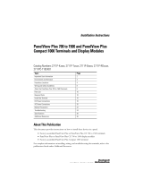
Hardware Features
The PanelView 5510 terminals are fixed hardware configurations that provide a
range of display sizes and operator input options.
Operator Control
All PanelView 5510 terminals have a color display with a touch screen and
navigation key, or a touch screen, navigation key, and keypad for operator control.
• Analog, resistive, touch screens provide accurate, durable touch with
excellent reliability for control of industrial applications.
• Keypad models are similar except for the number of function keys to the
left (L#) and right (R#) of the display. Larger models have more keys.
2
36
7
L1
L2
L3
L4
L5
L6
L8
L7
R9
R10
Esc
7
9
8
456
123
0
.
–
R11
R12
R13
R14
R16
R15
1
5
8
9
4
Table 1 - Hardware Features
Item Feature Description
1 Display/Keypad TFT color graphic displays with a touch screen and navigation button in a range of display sizes. Some models also have a keypad and
function keys providing additional operator input options.
• 6.5-in. touch or touch with keypad
• 7-in. wide screen with touch
• 9-in. wide screen with touch
• 10.4-in. touch or touch with keypad
• 12.1-in. wide screen with touch
• 15-in. touch or touch with keypad
• 19-in. touch
2 Power 18…30V DC (isolated)
3 Mounting slot The slots on the top, bottom, and sides of the terminal are used with mounting levers to mount the device to a panel or enclosure. The
number of slots varies by terminal size.
4 Ethernet ports Two 10/100Base-T, Auto MDI/MDI-X, EtherNet/IP ports for controller communication that supports DLR network topology.
5 USB host ports Two USB 2.0 high-speed (type A) host ports.
6 USB device port One USB 2.0 high-speed (type B) device port to connect a host computer that is software-feature dependent.
7Audio out IMPORTANT: The audio out feature is not functional. The feature is expected to be available in a future software release.
8 Status indicators Light-emitting diode indicators on back of unit provide status and fault conditions.
9 Secure Digital (SD) card slot One slot that supports an SD™ or SDHC™ card that is recommended in Table 6 on page 18
.

Rockwell Automation Publication 2715P-UM001C-EN-P - March 2019 13
Overview Chapter 1
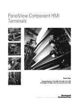
The physical keypad on the PanelView 5510 terminal is used during runtime to
initiate actions, control navigation, and enter data. The terminal also supports a
virtual keyboard and numeric keypad that opens on PanelView 5510 terminal
screens during runtime.
The terminal also supports the use of a physical keyboard and mouse when
connected to the USB ports.
ATTENTION: The keypad and touch screen support input from a finger, stylus,
and gloved hand for operation in dry or wet environments. The plastic stylus
must have a minimum tip radius of 1.3 mm (0.051 in.). Any other object or tool
can damage the keypad or touch screen.
ATTENTION: Do not perform multiple operations simultaneously. Multiple
simultaneous operations can result in unintended operation.
• Touch only one operating element on the screen with one finger at one time.
• Press only one key on the terminal at one time.
L8
4
14
3
2
Table 2 - PanelView 5510 Terminal Keypad
Item Feature Description
1 Navigation button Opens the navigation menu at the bottom of a screen and displays the contents of a project. The menu allows screen navigation and device
configuration.
2 Numeric keypad Contains numeric, decimal, minus, and these keys:
• Backspace - deletes the character to the left of the insertion point.
• Enter - inputs the currently highlighted key or enters a blank line if the insertion point is in the text box of the virtual keyboard.
• Tab-left, Tab-right - selects the previous or next control or input element.
• Esc - cancels or dismisses a dialog.
3 Navigation keys Provides navigation control.
• Arrow keys - selects a key on the virtual keyboard that is above, below, left, or right of the selected key. Arrow keys also move the cursor if the
cursor is in a text box.
• Home/End - moves the insertion point to the beginning or end of a text or numeric entry field.
• Page up/Page down - goes to the next or previous pages of a list.
4Function keys
• 6.5-in. terminal
• 10.4-in. terminal
• 15-in. terminal
Performs specific commands when configured for a screen or any of its graphic elements. For example, L1 can be configured to go to another
screen.
• L1…L6 and R1…R6
• L1…L8 and R1…R8
• L1…L10 and R1…R10

14 Rockwell Automation Publication 2715P-UM001C-EN-P - March 2019
Chapter 1 Overview
Touch Gestures
The PanelView 5510 terminal supports touch gestures to interact with screen
elements during runtime. Standard touch gestures include:
• Tap – Briefly touch the target on the HMI screen with your fingertip.
• Double-tap – Touch the target on the HMI screen twice quickly with
your fingertip.
• Drag – Move your fingertip over the target on the HMI screen without
contact loss.
• Long press – Touch and hold the target on the HMI screen for several
seconds.
For a list of actions you can perform by using touch gestures, see the View
Designer help.
Studio 5000 Environment
Use the Studio 5000 environment to create HMI applications for the PanelView
5510 terminal.
The Studio 5000 environment includes these applications:
• View Designer – you can create and design a project for a specific
PanelView 5510 terminal and download the project to the terminal.
You can create an application for any PanelView 5510 terminal and reuse
that same application across the entire platform.
• Logix Designer – you can develop control logic for a CompactLogix or
ControlLogix controller and download the logic to the controller.

Rockwell Automation Publication 2715P-UM001C-EN-P - March 2019 15
Overview Chapter 1
Figure 1 - How Studio 5000 Applications Work Together
The table describes how the View Designer and Logix Designer applications
work together to create an HMI runtime project.
Table 3 - Studio 5000 Applications and Tools
Item Component Description
1View Designer
application
A Studio 5000 application that is used to build HMI projects.
Studio 5000 View Designer projects are stored as VPD files that can be downloaded to the
PanelView 5510 terminal.
2 Tag browser A tool that is used to search for and select tags within a Studio 5000 Logix Designer ACD
project file. You can bind the tags to graphic element properties and properties of an HMI
screen. The Studio 5000 View Designer application uses the tag browser to read data from
an ACD file.
3Logix Designer
application
A Studio 5000 application that is used to develop control logic for an industrial
automation system. Studio 5000 Logix Designer application interfaces with controllers to
read and write tag information. Studio 5000 Logix Designer projects are stored as ACD
files that can be downloaded to the controller.
4 ACD file An Automation Controller Database (ACD) file. An ACD file is a Logix Designer project file
that contains the logic or code, including tags and data types, which runs within a
controller.
5 HMI project
(VPD file)
A View Project Database (VPD) file. A VPD project is a file that contains the operator
interface application, including HMI screens, controller references, and information about
the HMI device to run the application.
6 HMI device A Human Machine Interface (HMI) device, such as the PanelView 5510 terminal, which
runs the HMI project. At runtime, the HMI device communicates directly with the
controller.
7 Runtime The environment in which the runtime HMI project communicates with the controller.
During runtime, the HMI device runs the downloaded project, exchanges data with the
controller, animates displayed data, and responds to operator input.
8 Controller A logic controller such as a ControlLogix or CompactLogix 5370 controller.
LINK NET OK
1
2
3
4
5
7
6
8
View Designer
Application
Logix Designer
Application
Tag Browser
Offline
ACD File
HMI Project
(VPD File)
HMI Device
Controller
Runtime
Communication

16 Rockwell Automation Publication 2715P-UM001C-EN-P - March 2019
Chapter 1 Overview
EtherNet/IP
Communication
The PanelView 5510 terminals contain EtherNet/IP embedded switch
technology. These terminals communicate with ControlLogix controllers over an
Ethernet connection with DLR or linear network topologies. Star technology is
also supported when using switches.
The PanelView 5510 terminals can reside on EtherNet/IP networks that run
integrated motion and CIP Sync applications without adverse performance. The
terminal is not a consumer or producer of CIP Sync or motion packets.
Typical Configuration
Traditional DLR linear, and star network topologies are supported. See these
topics for examples:
• Device Level Ring Network Topology on page 35
• Linear Network Topology on page 36
• Star Network Topology on page 37
Catalog Number
Explanation
This table provides an explanation of the catalog numbers.
Bulletin Input Type Display Size Display Type Power – Special Option
||| |||
2715P- T = Touch 7 = 6.5-in.
(1)
C = Color, standard aspect ratio D = DC isolated – B = Without brand identity
(2)
B = Keypad with touch 7 = 7-in.
(1)
W = Color, wide aspect ratio
9 = 9-in.
10 = 10.4-in.
12 = 12.1-in.
15 = 15-in.
19 = 19-in.
(1) For the display size/display type combination, 7C designates the 6.5-in. standard display model, and 7W designates the 7-in. wide screen display model.
(2) A catalog number with -B at its end (for example, 2715P-T7WD-B) is a terminal without the Allen-Bradley® logo and product identification on the front bezel.

Rockwell Automation Publication 2715P-UM001C-EN-P - March 2019 17
Overview Chapter 1
Product Selection
This table provides product selection information.
Accessories
Tab l e 4 through Tab l e 8 list accessories for the PanelView 5510 terminals.
Protective overlays help protect your PanelView terminal touch screen and keys
from scratches, dust, fingerprints, and external damage from chemicals or
abrasive materials.
Cat. No. Display
Input
Power
Ethernet Memory
Touch Key and Touch Size Type Aspect Ratio Pixels (W x H) DLR RAM User
(1)
2715P-T7CD
2715P-T7CD-B
2715P-B7CD
2715P-B7CD-B
6.5-in. VGA TFT Color 4:3 640 x 480 DC Yes 1 GB 1 GB
2715P-T7WD
2715P-T7WD-B
— 7-in. wide WVGA TFT Color 5:3 800 x 480
2715P-T9WD
2715P-T9WD-B
— 9-in. wide
2715P-T10CD
2715P-T10CD-B
2715P-B10CD
2715P-B10CD-B
10.4-in. SVGA TFT Color 4:3 800 x 600
2715P-T12WD
2715P-T12WD-B
— 12.1-in.
wide
WXGA TFT Color 16:10 1280 x 800
2715P-T15CD
2715P-T15CD-B
2715P-B15CD
2715P-B15CD-B
15-in. XGA TFT Color 4:3 1024 x 768
2715P-T19CD
2715P-T19CD-B
— 19-in. SXGA TFT Color 5:4 1280 x 1024
(1) Non-volatile memory that is available to store projects.
Table 4 - Protective Overlays
Cat. No.
(1)
(1) Three overlays are shipped with each catalog number.
Display Size
Operator Input
Touch Key and Touch
2711P-RGT7SP 6.5-in. •
2711P-RGB7P •
2711P-RGT7W 7-in. wide •
2711P-RGT9SP 9-in. wide •
2711P-RGT10SP 10.4-in. •
2711P-RGB10P •
2711P-RGT12SP 12.1-in. wide •
2711P-RGT15SP 15-in. •
2711P-RGB15P •
2711P-RGT19P 19-in. •

18 Rockwell Automation Publication 2715P-UM001C-EN-P - March 2019
Chapter 1 Overview
SD and SDHC accessory cards in Tabl e 6 have been designed to meet industrial
robustness and environmental requirements. Rockwell Automation recommends
you use these accessory cards with the terminal to help reduce the chances of
corruption. Studio 5000 View Designer software requires the following for SD
cards that are inserted into the HMI device:
• 4 GB of free space
• A supported SDHC card type, preferably one listed in Table 6
• An environmental rating for the PanelView 5000 environment
• A supported format of either FAT32 or ext3
Ethernet Cables
See the Industrial Ethernet Media Brochure, publication 1585-BR001B, for
recommended Ethernet cables and media solutions.
Table 5 - Power Supplies and Power Terminal Blocks
Cat. No. Description Quantity
1606-XLP95E DIN-rail power supply, 24…28V DC output voltage, 95 W 1
1606-XLP100E DIN-rail power supply, 24…28V DC output voltage, 100 W 1
2711P-RSACDIN DIN-rail power supply, AC-to-DC, 100…250V AC, 50…60 Hz 1
2711P-RTBDSP 3-pin DC power terminal block (black with white labels for +, –, and GND) 10
Table 6 - Secure Digital (SD) Cards
(1)
(1) To help reduce the chance of corruption when you use SD Cards or USB drives with the terminal, Rockwell Automation
recommends that you use only the above SD card catalog numbers.
Cat. No. Description Quantity
1784-SD1 1-GB SD card 1
1784-SD2 2-GB SD card 1
1784-SDHC8 8-GB SDHC card 1
1784-SDHC32 32-GB SDHC card 1
2711C-RCSD USB to SD adapter for SD card 1
Table 7 - Mounting Hardware
Cat. No. Description Quantity
2711P-RMCP
(1)
(1) Catalog number 2711P-RMCP mounting levers are used with the PanelView 5510 terminals. Do not use gray mounting levers; they
are not compatible with PanelView 5510 terminals.
Mounting levers (black) 16
Table 8 - Battery Replacement
Cat. No. Description Quantity
2711P-RY2032 Lithium coin cell battery, CR2032 equivalent 1

Rockwell Automation Publication 2715P-UM001C-EN-P - March 2019 19
Chapter 2
Install the PanelView 5510 Terminal
Topic Page
Installation Precautions 20
North American Hazardous Locations 23
Mounting Considerations 25
Mounting Clearances 25
Panel Guidelines 26
Panel Cutout Dimensions 26
Product Dimensions 27
Prepare for Panel Mounting 28
Mount the Terminal in a Panel 31
Remove and Replace the DC Power Terminal Block 34
Connect to DC Power 35
Connect to a Network 36
Initial Startup 39
ATTENTION: Do not use a PanelView™ 5510 terminal for emergency stops or
other controls critical to the safety of personnel or equipment. Use separate
hard-wired operator interface devices that do not depend on solid-state
electronics.

20 Rockwell Automation Publication 2715P-UM001C-EN-P - March 2019
Chapter 2 Install the PanelView 5510 Terminal
Installation Precautions
Read and follow these precautions before you install the PanelView 5510
terminal.
Environment and Enclosure Information
ATTENTION: This equipment is intended for use in a Pollution Degree 2
industrial environment, in overvoltage Category II applications (as defined in IEC
60664-1), at altitudes up to 2000 m (6561 ft) without derating. The terminals
are intended for use with programmable logic controllers.
This equipment is considered Group 1, Class A industrial equipment according to IEC
CISPR 11. Without appropriate precautions, there can be difficulties with
electromagnetic compatibility in residential and other environments due to
conducted or radiated disturbances.
Korean Radio Wave Suitability Registration - When so marked this
equipment is registered for Electromagnetic Conformity Registration as
business equipment (A), not home equipment. Sellers or users are
required to take caution in this regard.
이 기기는 업무용 (A 급 ) 전자파적합기기로서 판 매자 또
는 사용자는 이 점을 주의하시기 바 라 며 , 가정외의 지역
에서 사용하는 것을 목적으 로 합니다 .
This equipment is supplied as open-type equipment. It must be mounted within an
enclosure that is suitably designed for those specific environmental conditions that
can be present, and appropriately designed to help prevent personal injury
resulting from accessibility to live parts. The interior of the enclosure must be
accessible only by the use of a tool. The terminals meet specified NEMA, UL Type,
and IEC ratings only when mounted in a panel or enclosure with the equivalent
rating. Subsequent sections of this publication can contain additional information
regarding specific enclosure type ratings that are required to comply with certain
product safety certifications.
In addition to this publication, see the following:
• Industrial Automation Wiring and Grounding Guidelines, publication 1770-4.1
,
for additional installation requirements.
• NEMA 250 and IEC 60529, as applicable, for explanations of the degrees of
protection provided by different types of enclosure.
/