Page is loading ...

Installation Instructions
Original Instructions
PanelView Plus 700 to 1500 and PanelView
Plus Compact 1000 Terminals and Display
Modules
Catalog Numbers 2711P-Kxxxx, 2711P-Txxxx, 2711P-Bxxxx, 2711P-RDxxxx, 2711PC-
T10C4D1
Summary of Changes
This document contains new and updated information as indicated in the following table.
Topic Page
Summary of Changes 1
Important User Information 2
About This Publication 3
Hazardous Locations 5
Wiring and Safety Guidelines 8
About the PanelView Plus 700 to 1500 Terminals 9
Parts List 10
Required Tools 10
Install the Terminal 11
DC Power Connections 17
AC Power Connections 21
Battery Precautions 23
Troubleshooting 25
Specifications 29
Additional Resources 31
Topic Page
Updated the Attention note in the section titled External Power Supply for Nonisolated DC Terminals and in the
section titled External Power for Isolated DC Terminals.
18

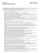
2 Rockwell Automation Publication 2711P-IN001J-EN-P - April 2018
PanelView Plus 700 to 1500 and PanelView Plus Compact 1000 Terminals and Display Modules
Important User Information
Read this document and the documents listed in the additional resources section about installation, configuration, and operation of
this equipment before you install, configure, operate, or maintain this product. Users are required to familiarize themselves with
installation and wiring instructions in addition to requirements of all applicable codes, laws, and standards.
Activities including installation, adjustments, putting into service, use, assembly, disassembly, and maintenance are required to be
carried out by suitably trained personnel in accordance with applicable code of practice.
If this equipment is used in a manner not specified by the manufacturer, the protection provided by the equipment may be impaired.
In no event will Rockwell Automation, Inc. be responsible or liable for indirect or consequential damages resulting from the use or
application of this equipment.
The examples and diagrams in this manual are included solely for illustrative purposes. Because of the many variables and
requirements associated with any particular installation, Rockwell Automation, Inc. cannot assume responsibility or liability for actual
use based on the examples and diagrams.
No patent liability is assumed by Rockwell Automation, Inc. with respect to use of information, circuits, equipment, or software
described in this manual.
Reproduction of the contents of this manual, in whole or in part, without written permission of Rockwell Automation, Inc., is
prohibited.
Throughout this manual, when necessary, we use notes to make you aware of safety considerations.
Labels may also be on or inside the equipment to provide specific precautions.
WARNING: Identifies information about practices or circumstances that can cause an explosion in a hazardous
environment, which may lead to personal injury or death, property damage, or economic loss.
ATTENTION: Identifies information about practices or circumstances that can lead to personal injury or death,
property damage, or economic loss. Attentions help you identify a hazard, avoid a hazard, and recognize the
consequence.
IMPORTANT
Identifies information that is critical for successful application and understanding of the product.
SHOCK HAZARD: Labels may be on or inside the equipment, for example, a drive or motor, to alert people that
dangerous voltage may be present.
BURN HAZARD: Labels may be on or inside the equipment, for example, a drive or motor, to alert people that
surfaces may reach dangerous temperatures.
ARC FLASH HAZARD: Labels may be on or inside the equipment, for example, a motor control center, to alert
people to potential Arc Flash. Arc Flash will cause severe injury or death. Wear proper Personal Protective
Equipment (PPE). Follow ALL Regulatory requirements for safe work practices and for Personal Protective
Equipment (PPE).

Rockwell Automation Publication 2711P-IN001J-EN-P - April 2018 3
PanelView Plus 700 to 1500 and PanelView Plus Compact 1000 Terminals and Display Modules
About This Publication
This document provides instructions on how to install these devices in a panel.
• Factory-assembled PanelView™ Plus or PanelView Plus CE 700 to 1500 terminals
• PanelView Plus or PanelView Plus CE 700 to 1500 display modules
• Factory-assembled PanelView Plus Compact 1000 terminal
For complete information on installing, wiring, and troubleshooting the terminals, refer to the
publications listed under Additional Resources
.

4 Rockwell Automation Publication 2711P-IN001J-EN-P - April 2018
PanelView Plus 700 to 1500 and PanelView Plus Compact 1000 Terminals and Display Modules
Environment and Enclosure
ControlNet Communication Port
This equipment is intended for use in a Pollution Degree 2 industrial environment, in
overvoltage Category II applications (as defined in IEC publication 60664-1), at altitudes up to
2000 m (6561 ft) without derating.
The terminals are intended for use with programmable logic controllers. Terminals that are AC
powered must also be connected to the secondary of an isolating transformer.
This equipment is considered Group 1, Class A industrial equipment according to IEC/CISPR
Publication 11. Without appropriate precautions, there may be potential difficulties ensuring
electromagnetic compatibility in other environments due to conducted as well as radiated
disturbance.
Korean Radio Wave Suitability Registration - This equipment is registered for Electromagnetic
Conformity Registration as business equipment (A), not home equipment. Sellers or users are
required to take caution in this regard.
This equipment is supplied as open-type equipment. It must be mounted within an enclosure
that is suitably designed for those specific environmental conditions that will be present and
appropriately designed to prevent personal injury resulting from accessibility to live parts. The
interior of the enclosure must be accessible only by the use of a tool. The terminals meet
specified NEMA Type and IEC ratings only when mounted in a panel or enclosure with the
equivalent rating. Subsequent sections of this publication may contain additional information
regarding specific enclosure type ratings that are required to comply with certain product
safety certifications.
In addition to this publication, see:
• Industrial Automation Wiring and Grounding Guidelines, for additional installation
requirements, publication 1770-4.1
.
• NEMA Standards publication 250 and IEC publication 60529, as applicable, for
explanations of the degrees of protection provided by different types of enclosure.
PanelView Plus terminals with ControlNet communications ports include a Network
Applications Port (NAP). This port is for temporarily connecting programming terminals
to devices on a ControlNet network, and are not intended for continuous operation.

Rockwell Automation Publication 2711P-IN001J-EN-P - April 2018 5
PanelView Plus 700 to 1500 and PanelView Plus Compact 1000 Terminals and Display Modules
Hazardous Locations
This equipment is suitable for these locations:
• Class I, Division 2 Groups A, B, C, D
• Class II, Division 2 Groups F, G
• Class III
• Ordinary, nonhazardous locations only
The following statement applies to use in hazardous locations.
The terminals have a temperature code of T4 when operating in a 55 °C (131 °F) maximum
ambient temperature. Do not install the terminals in environments where atmospheric gases have
ignition temperatures less than 135 °C (275 °F).
Explosion Hazard
• Substitution of components may impair suitability for hazardous locations.
• Do not disconnect equipment unless power has been switched off and area is known to be
nonhazardous.
• Do not connect or disconnect components unless power has been switched off.
• All wiring must comply with N.E.C. articles 501, 502, 503, and/or C.E.C. section 18-1J2 as
appropriate.
• Peripheral equipment must be suitable for the location in which it is used.

6 Rockwell Automation Publication 2711P-IN001J-EN-P - April 2018
PanelView Plus 700 to 1500 and PanelView Plus Compact 1000 Terminals and Display Modules
Environnements dangereux
Cet équipement ne peut être utilisé que dans les environnements suivants:
• Classe I, Division 2, Groupes A, B, C, D
• Classe II, Division 2, Groupes F, G
• Classe III
• ou environnements non-dangereux
La mise en garde suivante s’applique à une utilisation en environnement dangereux.
Le code de température de fonctionnement des terminaux PanelView Plus et PanelView Plus CE
est T4 pour une température ambiante maximale de 55 °C. N’installez pas les terminaux dans des
environnements contenant des gaz atmosphériques inflammables à moins de 135 °C.
DANGER D’EXPLOSION
• La substitution de composants peut rendre cet équipement impropre à une utilisation
en environnement dangereux.
• Ne pas déconnecter l’équipement sans s’être assuré que l’alimentation est coupée ou
que l’environnement est classé non dangereux.
• Ne pas connecter ou déconnecter des composants sans s’être assuré que l’alimentation
est coupée.
• L’ensemble du câblage doit être conforme, selon le cas, aux articles 501-4(b), 502-4(b)
et 503-3(b) du Code national de l’électricité des Etats-Unis.
• L’équipement périphérique doit être adapté à l’environnement dans lequel il est utilisé.

Rockwell Automation Publication 2711P-IN001J-EN-P - April 2018 7
PanelView Plus 700 to 1500 and PanelView Plus Compact 1000 Terminals and Display Modules
USB Ports
All PanelView Plus and PanelView Plus Compact terminals contain universal serial bus (USB)
ports that comply with hazardous location environments. This section details the field-wiring
compliance requirements and is provided in accordance with the National Electrical Code,
article 500.
Terminals Control Drawing
Selected nonincendive field wiring apparatus must have nonincendive circuit parameters
conforming with Table 2.
Table 1 - PanelView Plus USB Port Circuit Parameters
V
oc
I
sc
C
a
L
a
Groups A and B Groups C and D Groups A and B Groups C and D
5.25V DC 1.68 A 10 μF 10 μF 15 μH 15 μH
Table 2 - Required Circuit Parameters for the USB Peripheral Device
V
max
≥ V
oc
I
max
≥ I
sc
C
i
+ C
cable
≤ C
a
L
i
+ L
cable
≤ L
a
USB
Peripheral
Nonincendive Field
Wiring Apparatus
USB Port
Nonincendive Field Wiring
Associated Nonincendive Field Wiring Apparatus
PanelView Plus Host Product

8 Rockwell Automation Publication 2711P-IN001J-EN-P - April 2018
PanelView Plus 700 to 1500 and PanelView Plus Compact 1000 Terminals and Display Modules
Application Information
Per the National Electrical Code the circuit parameters of nonincendive field wiring apparatus
for use in hazardous locations shall be coordinated with the associated nonincendive field wiring
apparatus such that their combination remains nonincendive. The PanelView Plus terminals and
the USB peripheral device shall be treated in this manner.
The circuit parameters of the PanelView Plus USB port are given in Table 1. The USB peripheral
device and its associated cabling shall have circuit parameters with the limits given in Table 2 for
them to remain nonincendive when used with the PanelView Plus USB port. If cable capacitance
and inductance are not known the following values from ANSI/ISA-RP 12.06.01-2003 may be
used:
C
cable
= 197 μF/m (60 μF/ft)
L
cable
= 0.7 μF/m (0.20 μH/ft)
Nonincendive field wiring must be wired and separated in accordance with 501.10(B)(3) of the
National Electrical Code (NEC) ANSI/NFPA 70 or other local codes as applicable.
This associated nonincendive field wiring apparatus has not been evaluated for use in
combination with another associated nonincendive field wiring apparatus.
Wiring and Safety Guidelines
Use publication NFPA 70E, Electrical Safety Requirements for Employee Workplaces, IEC
60364 Electrical Installations in Buildings, or other applicable wiring safety requirements for the
country of installation when wiring the devices. In addition to the NFPA guidelines:
• Connect the device and other similar electronic equipment to its own branch circuit.
• Protect the input power by a fuse or circuit breaker rated at no more than 15 A.
Symbol Definitions
V
oc
Open circuit voltage of the host USB port.
I
sc
Maximum output current of the host USB port.
V
max
Maximum applied voltage rating of the USB peripheral device.
V
max
shall be greater than or equal to V
oc
in Table 1 (V
max
≥ V
oc ).
I
max
Maximum current to which the USB peripheral device can be subjected.
I
max
shall be greater than or equal to I
sc
in Table 1 (I
max
≥ I
sc
).
C
i
Maximum internal capacitance of the USB peripheral device.
C
a
Maximum allowed capacitance of the USB peripheral device and its associated cable. The sum of C
i
of the
USB peripheral device and C
cable
of the associated cable shall be less than or equal to C
a
(C
i
+ C
cable
≤ C
a
).
L
i
Maximum internal inductance of the USB peripheral device.
L
a
Maximum allowed inductance of the USB peripheral device and its associated cable. The sum of L
i
of the
USB peripheral device and L
cable
of the associated cable shall be less than or equal to L
a
(L
i
+ L
cable
≤ L
a
).

Rockwell Automation Publication 2711P-IN001J-EN-P - April 2018 9
PanelView Plus 700 to 1500 and PanelView Plus Compact 1000 Terminals and Display Modules
• Route incoming power to the device by a separate path from the communication lines.
• Cross power and communication lines at right angles if they must cross.
• Communication lines can be installed in the same conduit as low-level
DC I/O lines (less than 10V).
• Shield and ground cables appropriately to avoid electromagnetic interference (EMI).
• Grounding minimizes noise from EMI and is a safety measure in electrical installations.
For more information on grounding recommendations, refer to the National Electrical Code
published by the National Fire Protection Association.
For more information, refer to Wiring and Grounding Guidelines for PanelView Plus Terminals
Technical Data, publication 2711P-TD001
. You can find this publication in the Literature
Library website, http://literature.rockwellautomation.com.
About the PanelView Plus 700 to 1500 Terminals
The PanelView Plus terminals have these modular components:
• Display module (700, 1000, 1250, and 1500)
• Logic module with AC or DC power, CompactFlash card slot, Ethernet port, serial port,
and USB ports
• Internal CompactFlash card with firmware or operating system, RAM memory (SO-
DIMM)
• Communication module for specific communication protocols
These items can be ordered as separate components for field installation or factory assembled per
your configuration. The base-configured unit includes the display module and the logic module
with internal CompactFlash and RAM.
Modular Components
If the modules are ordered separately, attach the logic and communication module to the display
module before panel installation. See the instructions shipped with each module.
The logic module for the terminals is available with or without RAM and CompactFlash
preinstalled. If memory is ordered separately, you must install the memory before attaching the
logic module to the display module. See the instructions shipped with the logic module.
Communication Module
Logic Module
Display Module
Power Input, AC or DC
Ethernet Port
Serial Port
USB Ports
CompactFlash Card Slot

10 Rockwell Automation Publication 2711P-IN001J-EN-P - April 2018
PanelView Plus 700 to 1500 and PanelView Plus Compact 1000 Terminals and Display Modules
About the PanelView Plus Compact 1000 Terminal
The PanelView Plus Compact 1000 terminal has a fixed configuration. It does not support
communication modules, or the replacement of the logic module. The 1000 terminal contains a
non-isolated DC power supply.
The PanelView Plus Compact 1000 terminal has these features:
• 1000 touch screen display module
• USB ports (2)
• RS-232 serial port
• 10/100Base T Ethernet port
• Power input, 24V DC non-isolated
• CompactFlash Type 1 card slot
Parts List
These items are shipped with the terminals:
• Power terminal block
• Mounting clips
• FactoryTalk View® software preloaded
• Installation instructions and panel cutout template
Required Tools
These tools are required for panel installation:
• Panel cutout tools
• Small, slotted screwdriver
• Torque wrench (lb•in)
USB Ports
RS-232 Serial Port
Ethernet Port
Power Input, 24V DC
Compact Flash

Rockwell Automation Publication 2711P-IN001J-EN-P - April 2018 11
PanelView Plus 700 to 1500 and PanelView Plus Compact 1000 Terminals and Display Modules
Install the Terminal
Before installing the terminal in a panel, review the following topics:
• Mounting clearances
• Panel cutout dimensions
• Product dimensions
Mounting Clearances
Allow adequate clearance around the terminal, inside the enclosure, for adequate ventilation.
Consider heat produced by other devices in the enclosure. The ambient temperature around the
terminals must be between 0…55 °C (32…131 °F).
These minimum clearances are required for ventilation.
• Top clearance: 51 mm (2 in.)
• Bottom clearance: 102 mm (4 in.)
• Side clearances: 25 mm (1 in.)
• Back clearance: 25 mm (1 in.)
Minimum side clearance for insertion of memory card is 102 mm (4 in.).
Panel Cutout Dimensions
Use the full size template shipped with your terminal to mark the cutout dimensions.
Terminal Type Height, mm (in.) Width, mm (in.)
700 Keypad or Keypad and Touch 167 (6.57) 264 (10.39)
700 Touch 154 (6.08) 220 (8.67)
1000 Keypad or Keypad and Touch 224 (8.8) 375 (14.75)
1000 Touch 224 (8.8) 305 (12.00)
1250 Keypad or Keypad and Touch 257 (10.11) 390 (15.35)
1250 Touch 257 (10.11) 338 (13.29)
1500 Keypad or Keypad and Touch 305 (12.00) 419 (16.50)
1500 Touch 305 (12.00) 391 (15.40)

12 Rockwell Automation Publication 2711P-IN001J-EN-P - April 2018
PanelView Plus 700 to 1500 and PanelView Plus Compact 1000 Terminals and Display Modules
Mount the Terminal in a Panel
Mounting clips secure the terminal to the panel. The number of clips you use
(4, 6, or 8) varies by terminal type.
Follow these steps to mount the terminal in a panel.
1. Cut an opening in the panel by using the panel cutout shipped with the terminal.
2. Make sure the terminal sealing gasket is properly positioned on the terminal.
This gasket forms a compression type seal. Do not use sealing compounds.
3. Install the legend strips before installing the terminal if you are using keypad legend
strips on keypad terminals.
Be careful not to pinch the legend strip during installation.
4. Place the terminal in the panel cutout.
Disconnect all electrical power from the panel before making the panel cutout.
Make sure the area around the panel cutout is clear.
Take precautions so metal cuttings do not enter any components already installed in the
panel.
Failure to follow these instructions may result in personal injury or damage to panel
components.
Sealing Gasket

Rockwell Automation Publication 2711P-IN001J-EN-P - April 2018 13
PanelView Plus 700 to 1500 and PanelView Plus Compact 1000 Terminals and Display Modules
5. Slide the ends of the mounting clips into the slots on the terminal.
6. Tighten the mounting clip screws by hand until the gasket seal contacts the mounting
surface uniformly.
7. Tighten the mounting clip screws to a torque of 0.90…1.1 N•m
(8…10 lb•in) by using the specified torque sequence, making sure not to overtighten.
Tighten the mounting clips to the specified torque to provide a proper seal and
prevent damage to the product. Rockwell Automation assumes no responsibility
for water or chemical damage to the product or other equipment within the
enclosure because of improper installation.
Mounting Clip Slot
Mounting Clip
8 Clips
6 Clips
4 Clips
14
32
13
5
46
2
1
6
52
3
7
8
4

14 Rockwell Automation Publication 2711P-IN001J-EN-P - April 2018
PanelView Plus 700 to 1500 and PanelView Plus Compact 1000 Terminals and Display Modules
Product Dimensions
The table provides product dimensions for the terminals including depth dimensions for the:
• base configured unit (display module and logic module).
• base configured unit with communication module.
The illustration shows product dimensions for the PanelView Plus and PanelView Plus Compact
1000 touch only terminals. The other size terminals look similar. Measurements are in mm (in.).
Terminal Type
Height, Approx.,
mm (in.)
Width,
Approx.,
mm (in.)
Depth, Approx., mm (in.)
700 Keypad or Keypad and Touch 193 (7.58) 290 (11.40)
55 (2.18)
display to logic module
83 (3.27)
display to comm module
700 Touch Screen 179 (7.04) 246 (9.68)
1000 Keypad or Keypad and Touch 248 (9.77) 399 (15.72)
1000 Touch Screen 248 (9.77) 329 (12.97)
1250 Keypad or Keypad and Touch 282 (11.12) 416 (16.36)
1250 Touch Screen 282 (11.12) 363 (14.30)
1500 Keypad or Keypad and Touch 330 (12.97) 469 (18.46) 65 (2.55)
display to logic module
93 (3.65)
display to comm module
1500 Touch Screen 330 (12.97) 416 (16.36)

Rockwell Automation Publication 2711P-IN001J-EN-P - April 2018 15
PanelView Plus 700 to 1500 and PanelView Plus Compact 1000 Terminals and Display Modules
1000 Terminal Dimensions
Keypad or Keypad & Touch
Touch Screen
a 55 (2.18) Display to Logic Module
b 83 (3.27) Display to Comm Module
a 55 (2.18) Display to Logic Module
248 (9.77)
399 (15.72)
b
a
b
a
329 (12.97)
248 (9.77)

16 Rockwell Automation Publication 2711P-IN001J-EN-P - April 2018
PanelView Plus 700 to 1500 and PanelView Plus Compact 1000 Terminals and Display Modules
Ethernet Wiring
Use Belden 7921A shielded Ethernet Category 5e cable according to TIA 568-B.1 and RJ45
connector according to IEC 60603-7 for compliance with Marine emissions limits and European
Union 89/336/EEC EMC Directive.
The maximum cable length between the terminal’s Ethernet port and a 10/100 Base-T port on
an Ethernet hub (without repeaters or fiber) is 100 m (328 ft).
Remove and Install the Power Terminal Block
The terminals are shipped with a power terminal block installed. You can remove the terminal
block for ease of installation, wiring, and maintenance.
• Series A to D, DC logic modules use a 3-position terminal block.
• Series E or later, DC logic modules use a 2-position terminal block.
• All logic modules with an AC power input use a 3-position terminal block.
Explosion Hazard
Substitution of components may impair suitability for hazardous locations.
Do not disconnect equipment unless power has been switched off and area is known to be
nonhazardous.
Do not connect or disconnect components unless power has been switched off.
All wiring must comply with N.E.C. articles 501, 502, 503, and/or C.E.C. section 18-1J2 as
appropriate.
Peripheral equipment must be suitable for the location in which it is used.
Disconnect all power before installing or replacing components. Failure to disconnect power
may result in electrical shock or damage to the terminal.

Rockwell Automation Publication 2711P-IN001J-EN-P - April 2018 17
PanelView Plus 700 to 1500 and PanelView Plus Compact 1000 Terminals and Display Modules
Follow these steps to remove the terminal block.
1. Loosen the two screws that secure the terminal block.
2. Gently pull the terminal block away from the connector.
Follow these steps to install the terminal block.
1. Reattach the terminal block to the connector until seated.
2. Tighten the two screws that secure the terminal block to the connector.
DC Power Connections
DC-powered PanelView Plus devices have an integrated 24V DC power supply. Both isolated
and non-isolated power supplies have these ratings:
• 24V DC nominal (18…32V DC)
• 70 W maximum (2.9 A at 24V DC)
The power supply is internally protected against reverse polarity of the DC+ and DC-
connections. Connecting DC+ or DC- to the earth/ground terminal may damage the device.
The input power terminal block supports these wire sizes.
Wire Specifications for DC Input Power Terminal Block
Logic Module Wire Type
Dual-wire
Gauge
(1)
(1) Two-wire max per terminal.
Single-wire
Gauge
Terminal Screw
Torque
Series A to D
Stranded
or solid
Cu 90 °C
(194 °F)
22…16 AWG 22…14 AWG
0.23…0.34 N•m
(2…3 lb•in)
Series E and later 0.56 N•m (5 lb•in)
3-position AC or DC
Terminal Block
2-position DC Terminal Block (series
E or later)

18 Rockwell Automation Publication 2711P-IN001J-EN-P - April 2018
PanelView Plus 700 to 1500 and PanelView Plus Compact 1000 Terminals and Display Modules
External Power Supply For Non-isolated DC Terminals
Use a single, 24V DC power supply to power each PanelView Plus device, such as catalog
number 2711P-RSACDIN. Using a separate, isolated and ungrounded source to power each
terminal prevents ground loop currents from damaging the terminals.
The output on the power supply must be isolated from the input and not connected to earth/
ground.
Multiple AC Power Supplies to Power Multiple DC Terminals
External Power for Isolated DC Terminals
Use an SELV or PELV 24V DC power supply, such as catalog number 2711P-RSACDIN, to
power the isolated DC PanelView Plus terminal.
The isolated DC terminals may be powered by the same power source as other equipment.
TIP To identify non-isolated DC logic modules refer to the PanelView Plus Terminals User Manual,
publication 2711P-UM001
.
Use a safety extra-low voltage (SELV) or protective extra-low voltage (PELV) power supply as
required by local wiring codes for your installation. The SELV or PELV power sources provide
protection so that under normal and single-fault conditions, the voltage between the
conductors, and between the conductors and functional earth or protective earth does not
exceed a safe value.
TIP
Isolated DC logic modules are identified by catalog number 2711P-RPxDx.
Use a safety extra-low voltage (SELV) or protective extra-low voltage (PELV) power supply as
required by local wiring codes for your installation. The SELV or PELV power sources provide
protection so that under normal and single-fault conditions, the voltage between the
conductors, and between the conductors and functional earth or protective earth does not
exceed a safe value.
Circuitry Circuitry
dc+
PanelView Plus
PanelView Plus
AC/DC Power Supply
L1L2
dc- dc+ dc-
L1L2
(2711P-RSACDIN)
(2711P-RSACDIN)
AC/DC Power Supply

Rockwell Automation Publication 2711P-IN001J-EN-P - April 2018 19
PanelView Plus 700 to 1500 and PanelView Plus Compact 1000 Terminals and Display Modules
Earth/Ground Connection
PanelView Plus devices with a DC power input have a earth/ground terminal that you must
connect to a low-impedance earth/ground. The earth/ground connection is on the rear of the
display module.
The earth/ground terminal requires a minimum wire gauge.
On most PanelView Plus devices, the earth/ground terminal is internally connected to the DC-
terminal within the product.
The PanelView Plus devices have isolated and non-isolated communication ports.
For more information refer to the PanelView Plus Terminals User Manual, publication 2711P-
UM001.
IMPORTANT The earth/ground connection to ground is mandatory. This connection is required for noise
immunity, reliability, and Electromagnetic Compliance (EMC) with the European Union (EU)
EMC directive for CE-mark conformance. This connection is required for safety by Underwriters
Laboratory.
Earth/Ground Wire Specifications for DC Power
Symbol Wire Type Wire Gauge Terminal Screw Torque
GND Stranded or solid Cu 90 °C (194 °F) 14…10 AWG 1.13…1.36 N•m (10…12 lb•in)
Damage or malfunction can occur when a voltage potential exists between two separate
ground points. Make sure the terminal does not serve as a conductive path between ground
points at different potentials.

20 Rockwell Automation Publication 2711P-IN001J-EN-P - April 2018
PanelView Plus 700 to 1500 and PanelView Plus Compact 1000 Terminals and Display Modules
Connect DC Power
Follow these steps to connect the terminal DC power.
1. Verify that the terminal is not connected to a power source.
2. Secure the DC power wires to the terminal block.
Follow the markings on the terminal blocks and the terminal for proper connections.
3. Secure the earth/ground wire to the earth/ground terminal screw at the bottom of the
display.
DC Power Supply Connections
Explosion Hazard - Do not disconnect equipment unless power has been switched off and area
is known to be nonhazardous.
Disconnect all power before installing or replacing components. Failure to disconnect power
may result in electrical shock or damage to the terminal.
GND
2-position Terminal Block
(series E or later logic modules)
3-position Terminal Block
(series A to D logic modules)
+
–
–
+
Earth/Ground to Ground Bus
DC -
DC+
DC-
DC+
GND
/