Allen-Bradley 2711P-RN6K Installation guide
- Type
- Installation guide

Installation Instructions
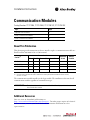
Communication Modules
Catalog Numbers 2711P-RN6, 2711P-RN6K, 2711P-RN15S, 2711P-RN15SK
About This Publication
This document provides instructions on how to install or replace a communication module on a
PanelView Plus 700, 1000, 1250, or 1500 terminal.
The communication module installs over the logic module. The installation is the same for all
communication modules regardless of communication type.
Additional Resources
You can view or download publications at
http://www.rockwellautomation.com/literature/. To order paper copies of technical
documentation, contact your local Rockwell Automation distributor or sales
representative.
Topic Page
Important User Information 2
Install a Communication Module 3
Install a Communication Module 4
Cat. No.
(1)
(1) These installation instructions also apply to other cat. no. 2711P-RNxx communication modules.
Communication
Conformal
Coated
Marine
Certified
DH+ DH-485 Remote I/O
(2)
(2) Only supported on PanelView Plus 700 to 1500 terminals running FactoryTalk View Machine Edition software,
version 5.1 or earlier.
ControlNet
2711P-RN6 • • • •
2711P-RN6K • • • •
2711P-RN15S • •
2711P-RN15SK • •
IMPORTANT
The logic module must be attached to a PanelView Plus display module before you attach
the communication module.
Spare Allen-Bradley Parts

2 Communication Modules
Rockwell Automation Publication 2711P-IN003D-EN-P - June 2010
Important User Information
Solid-state equipment has operational characteristics differing from those of electromechanical equipment.
Safety Guidelines for the Application, Installation and Maintenance of Solid State Controls (Publication SGI-1.1
available from your local Rockwell Automation sales office or online at
http://www.rockwellautomation.com/literature/
) describes some important differences between solid-state
equipment and hard-wired electromechanical devices. Because of this difference, and also because of the wide
variety of uses for solid-state equipment, all persons responsible for applying this equipment must satisfy
themselves that each intended application of this equipment is acceptable.
In no event will Rockwell Automation, Inc. be responsible or liable for indirect or consequential damages
resulting from the use or application of this equipment.
The examples and diagrams in this manual are included solely for illustrative purposes. Because of the many
variables and requirements associated with any particular installation, Rockwell Automation, Inc. cannot
assume responsibility or liability for actual use based on the examples and diagrams.
No patent liability is assumed by Rockwell Automation, Inc. with respect to use of information, circuits,
equipment, or software described in this manual.
Reproduction of the contents of this manual, in whole or in part, without written permission of Rockwell
Automation, Inc., is prohibited.
Throughout this manual, when necessary, we use notes to make you aware of safety considerations.
WARNING: Identifies information about practices or circumstances that can cause an
explosion in a hazardous environment, which may lead to personal injury or death, property
damage, or economic loss.
ATTENTION: Identifies information about practices or circumstances that can lead to personal
injury or death, property damage, or economic loss. Attentions help you identify a hazard, avoid
a hazard and recognize the consequences.
SHOCK HAZARD: Labels may be on or inside the equipment, for example, drive or motor, to
alert people that dangerous voltage may be present.
BURN HAZARD: Labels may be on or inside the equipment, for example, drive or motor, to
alert people that surfaces may reach dangerous temperatures.
IMPORTANT Identifies information that is critical for successful application and understanding of the
product.

Communication Modules 3
Rockwell Automation Publication 2711P-IN003D-EN-P - June 2010
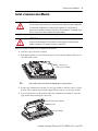
Install a Communication Module
Follow these steps to install a new communication module.
1. Disconnect power from the terminal.
2. If the display module is removed from the panel, set the terminal, display side down, on a
clean, flat, stable surface.
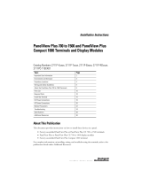
3. Position the communication module over the logic module so that the connector on the
bottom of the communication module aligns with the connector on the logic module.
4. To prevent ESD between the modules, allow the communication module to touch the
logic module before making the connection.
WARNING: Explosion Hazard
Do not connect or disconnect any communication cable with power applied to
this device or any device on a network. An electrical arc could cause an
explosion in hazardous location installations. Be sure power is removed or the
area is known to be nonhazardous before proceeding.
ATTENTION: Work in a static-free environment and wear a properly grounded
electrostatic discharge (ESD) wristband. Do not touch the communication
module connector or its internal circuitry to avoid ESD.
TIP
Logic module might look different depending on catalog number.
Connector for
Communication Module
Connector
Communication Module
Logic Module
Spare Allen-Bradley Parts

Rockwell Automation Publication 2711P-IN003D-EN-P - June 2010 PN-77996
Supersedes Publication 2711P-IN003C-MU-P - March 2007 Copyright © 2010 Rockwell Automation, Inc. All rights reserved. Printed in the U.S.A.
Allen-Bradley, DH+, FactoryTalk View Machine Edition, PanelView Plus, Rockwell Software, and Rockwell Automation are trademarks of
Rockwell Automation, Inc.
Trademarks not belonging to Rockwell Automation are property of their respective companies.
Rockwell Otomasyon Ticaret A.Ş., Kar Plaza İş Merkezi E Blok Kat:6 34752 İçerenköy, İstanbul, Tel: +90 (216) 5698400
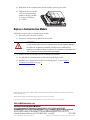
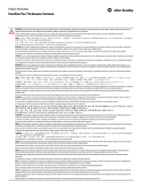
5. Push down on the communication module until the connectors are seated.
6. Tighten the four screws that
secure the communication
module to the logic module
to a torque of 0.58 N•m
(5…7 lb•in).
Replace a Communication Module
Follow these steps to replace a communication module.
1. Disconnect power from the terminal.
2. Disconnect communication cables from the module.
3. Remove the four screws that secure the communication module.
4. Carefully lift the communication module away from the logic module.
5. Install the new communication module by following steps 3…6 under Install a
Communication Module on page 3.
WARNING: Explosion Hazard
Do not connect or disconnect any communication cable with power applied to
this device or any device on a network. An electrical arc could cause an
explosion in hazardous location installations. Be sure power is removed or the
area is known to be nonhazardous before proceeding.
-
 1
1
-
 2
2
-
 3
3
-
 4
4


Allen-Bradley 2711P-RN6K Installation guide
- Type
- Installation guide
Ask a question and I''ll find the answer in the document
Finding information in a document is now easier with AI
Related papers
-
Allen-Bradley PanelView Plus 6 700 User manual
-
-
Allen-Bradley 2711P-B10C4A8 User manual
-
-
-
-
-
-
-
Other documents
-
 Rockwell Automation PanelView Plus 1250 User manual
-
 Rockwell Automation 2711P-RPD Installation Instructions Manual
-
 Rockwell Automation Allen-Bradley PanelView 5510 Series User manual
-
 Rockwell Automation PanelView Plus 1250 User manual
-
Rockwell Automation 1768-L43 Quick start guide
-
 Rockwell Automation 2711P-RC2 Installation Instructions Manual
-
 Rockwell Automation PanelView Plus 1250 Specification
-
 Rockwell Automation Allen-Bradley PanelView Plus 7 Product information
-
 Rockwell Automation 2711C-T6C Quick start guide
-
 Rockwell Automation Allen-Bradley ControlNet 1756-CNB User manual


