Page is loading ...

ID TECH
10721 Walker Street, Cypress, CA 90630-4720
Tel: (714) 761-6368 Fax (714) 761-8880
www.idtechproducts.com
VP8800 User Manual
Rev. K
17 August, 2020

Page | 2
Copyright© 2020 by International Technologies and Systems Corporation (ID TECH). All rights reserved.
ID TECH
10721 Walker Street
Cypress, CA 90630
USA
This document, as well as the hardware and software it describes, is furnished under license and may
only be used in accordance with the terms of such license. The content of this paper is furnished for
informational use, subject to change without notice, and not to be construed as a commitment by ID
TECH. ID TECH assumes no responsibility or liability for any errors or inaccuracies that may appear in this
document.
Except as permitted by such license, no part of this publication may be reproduced or transmitted by
electronic, mechanical, recorded, or any other method, or translated into another language or language
form without the express written consent of ID TECH. ID TECH is a registered trademark of International
Technologies and Systems Corporation. ViVOpay and Value through Innovation are trademarks of
International Technologies and Systems Corporation. Other trademarks are the property of the
respective owner.
Warranty Disclaimer: The services and hardware are provided "as is" and "as-available" and the use of
these services and hardware are at the user’s own risk. ID TECH does not make, and hereby disclaims,
any and all other express or implied warranties, including, but not limited to warranties of
merchantability, title, fitness for a particular purpose, and any warranties arising from any course of
dealing, usage, or trade practice. ID TECH does not warrant that the services or hardware will be
uninterrupted, error-free, nor completely secure.

Page | 3
FCC Regulatory Compliance
FCC warning statement
This device complies with Part 15 of the FCC Rules. Operation is subject to the following two conditions:
(1) this device may not cause harmful interference, and (2) this device must accept any interference
received, including interference that may cause undesired operation.
The user manual for an intentional or unintentional radiator shall caution the user that changes or
modifications not expressly approved by the party responsible for compliance could void the user’s
authority to operate the equipment.
Note: The grantee is not responsible for any changes or modifications not expressly approved by the
party responsible for compliance. Such modifications could void the user’s authority to operate the
equipment.
Note: This equipment has been tested and found to comply with the limits for a Class B digital device,
pursuant to part 15 of the FCC Rules. These limits are designed to provide reasonable protection against
harmful interference in a residential installation. This equipment generates uses and can radiate radio
frequency energy and, if not installed and used in accordance with the instructions, may cause harmful
interference to radio communications. However, there is no guarantee that interference will not occur
in a particular installation. If this equipment does cause harmful interference to radio or television
reception, which can be determined by turning the equipment off and on, the user is encouraged to try
to correct the interference by one or more of the following measures:
• Reorient or relocate the receiving antenna.
• Increase the separation between the equipment and the receiver.
• Connect the equipment into an outlet on a circuit different from that to which the receiver is
connected.
• Consult the dealer or an experienced radio/TV technician for help.
This device complies with FCC RF radiation exposure limits set forth for an uncontrolled environment.
The antenna(s) used for this transmitter must not be co-located or operating in conjunction with any
other antenna or transmitter and must be installed to provide a separation distance of at least 20cm
from all persons.
Cautions and Warnings
Caution: The VP8800 should be mounted at least 1 foot (30 cm) away from other
VP8800. Can be adjusted based on lane setup.
Caution: Danger of Explosion if battery is incorrectly replaced. Replace only with same or
equivalent type recommended by the manufacturer. Discard used batteries according to
the manufacturer’s instructions.
Warning: Avoid close proximity to radio transmitters which may reduce the capability of
the reader.

Page | 4
Table of Contents
1. GETTING STARTED .............................................................................................................................................. 5
2. FEATURES........................................................................................................................................................... 5
3. GETTING STARTED .............................................................................................................................................. 6
3.1. Unpacking the VP8800 ....................................................................................................................................... 6
3.2. Data on production and personalization ............................................................................................................ 6
4. INSTALLING THE VP8800 .................................................................................................................................... 7
4.1. Site Planning ....................................................................................................................................................... 7
4.2. PCI PED Compliance ........................................................................................................................................... 7
4.3. Verifying PCI Compliance ................................................................................................................................... 7
4.3.1. Retesting Requirements .............................................................................................................................. 8
4.3.2. 24-Hour Device Reboot ............................................................................................................................... 8
4.4. Radio Frequency Interference ............................................................................................................................ 8
4.5. Installation .......................................................................................................................................................... 8
4.6. Connecting the VP8800 ...................................................................................................................................... 8
4.6.1. Accessing the Connectors ............................................................................................................................ 8
4.7. Key Replacement .............................................................................................................................................. 12
4.8. Loss or theft ...................................................................................................................................................... 12
4.9. Testing the Installation ..................................................................................................................................... 12
4.9.1. Transaction Test ........................................................................................................................................ 12
4.9.2. LED Behavior ............................................................................................................................................. 12
4.9.3. To test a transaction ................................................................................................................................. 12
5. DECOMMISSIONING SRED DEVICES.................................................................................................................. 13
6. TROUBLESHOOTING AND MAINTENANCE ........................................................................................................ 14
6.1. Onboard Diagnostics ........................................................................................................................................ 15
6.2. Accessing the Onboard Diagnostic Tests .......................................................................................................... 15
6.3. Maintenance .................................................................................................................................................... 17
6.3.1. Replacing the Stylus .................................................................................................................................. 17
6.4. Upgrading Firmware ......................................................................................................................................... 17
7. APPENDIX A: SPECIFICATIONS .......................................................................................................................... 19
8. GLOSSARY ........................................................................................................................................................ 21

Page | 5
1. Getting Started
The VP8800 is an all-in-one card reader that can accommodate contact EMV, magstripe, and contactless
(NFC) payments and offers PIN pad (chip-and-PIN) capability and electronic signature capture. It is
designed to integrate easily with existing POS systems and requires minimal counter space at checkout
stands.
The VP8800 is a PCI-certified, SRED-compliant counter-top reader featuring RS-232 (serial), Ethernet,
and USB 2.0 communications to POS systems.
The VP8800 includes support for the following contactless payment applications:
• Support for Apple Pay, including VAS protocol
• Support for Google Pay, including Smart Tap
• Support for Samsung Pay
• Support for Mifare Suite
• Support for Secure SoftSAM(s)
• Support for Payment Card Brands:
o VISA VCPS
o MasterCard MCL
o AMEX Expresspay
o Discover DPAS
o Interac Flash
o UPI Global (Formerly CUP)
This document assumes that users are familiar with their host POS systems and all related functions.
2. Features
The VP8800 supports the following features:
• PCI 5.X certified
• SRED (Secure Reading and Exchange of Data) compliant, with tamper detection and fulltime
encryption*
• ANSI X.9-24 DUKPT key management
• ISO14443 type A/B and Mifare based contactless payment transactions
• ISO 18092 support for peer-to-peer NFC devices and smartphones
• Support for contactless transactions via NFC devices
• PIN entry for PIN/debit and chip-and-PIN transactions
• Magnetic stripe card transactions
• Electronic signature capture
• Three SAM card slots provided
• One SD card slot provided
• RJ-45 cable and Ethernet support
*Note that for encryption to be enabled, the VP8800 must be key-injected. ID TECH is a certified Key
Injection Facility. Contact your ID TECH representative for details.

Page | 6
3. Getting Started
3.1. Unpacking the VP8800
The VP8800 requires a data cable and, if the data cable does not supply power, a 5VDC 1.2A power
supply. The data cable is not included with the VP8800 and must be purchased separately from ID TECH.
Verify that you have all the required components for the installation:
VP8800 (PN: IDPP-1881)
Interface Cables:
• Serial Data Cable (PN 80143236-001)
• USB Data Cable (PN 80143234-001)
• Ethernet Cable (PN 80143235-001)
Power supply (included)
You may also need a contactless test card (ViVO Contactless Test Card P/N 241-0015-03).
3.2. Data on production and personalization
The device has been loaded with a serial number, MAC address, data encryption key, and PIN encryption
key by the factory.

Page | 7
4. Installing the VP8800
Before connecting and mounting the VP8800, plan the installation to conform to PCI 5.X requirements
and minimize radio frequency interference. After determining the location and mounting of the VP8800,
connect it to power and the POS terminal. Finally, test the VP8800 to make sure the installation is
successful.
4.1. Site Planning
Two environmental considerations affect VP8800 installation. PCI certification has specific restrictions
on how the reader is positioned to prevent PIN theft. Also consider objects and devices near the reader
that may affect the performance of the contactless radio frequency antenna.
4.2. PCI PED Compliance
The VP8800 is a PCI 5.x certified PIN/Debit payment device. PCI 5.x certification requires that sufficient
protection be provided to ensure that entering a PIN number CANNOT be viewed by a third party (such
as another customer standing nearby, the cashier, or a security camera).
The VP8800 has design elements, such as a recessed keypad, that meet some of these requirements.
However, to fully implement PCI 5.x, be sure to consider the following:
1. The VP8800 must be in a location that will NOT force a customer to enter a PIN that can be
viewed by a third party (for example, a customer must tilt or rotate the device for better
accessibility due to objects blocking a card swipe).
2. If the VP8800 is elevated on a mounting stand, shielding must be provided on the mount to
prevent a PIN being viewed by a third party.
3. If the VP8800 is mounted on a counter top, additional shielding (which can include other devices
such as a cash register as long as conditions in (1) above are met) must be provided to ensure
that the PIN cannot be viewed by a third party (including cashier and security camera).
WARNING: PCI requires that the device be mounted so that manual PIN entry cannot be observed by a
third party (such as another customer standing in line, the cashier at the counter, or a security camera
mounted in the ceiling to observe the cash register area). If the PIN entry can be observed, the store
owner may be responsible for any losses incurred by the customer if it can be determined that the
customer’s PIN was stolen at this location.
4.3. Verifying PCI Compliance
Before completing the installation, verify that the VP8800 is positioned so that the PIN entry is not
visible to other customers, the cashier behind the counter, or video surveillance cameras. If PIN entry is
visible, the VP8800 must be repositioned or shielding added until none of the above parties can observe
PIN entry.
These tests usually require at least two people—one to simulate entering the PIN while the other
attempts to view the keypad:
• Can Another Customer View the PIN: While one person stands at the VP8800 with their hand
positioned to enter the PIN, the other tester should try to observe the keypad from behind and
beside the first person.

Page | 8
• Can the Cashier View the PIN: While one person stands at the VP8800 with their hand
positioned to enter the PIN, the other tester should stand behind the counter and try to observe
the PIN keypad. The second tester should move around a little to see if there is a position where
they can observe PIN entry.
• Can the Video Camera View the PIN: While one person stands at the VP8800 with their hand
positioned to enter the PIN, the other tester should observe what is being recorded by any video
camera with a view of the VP8800. This may require playing back a recording to see if PIN entry
is visible. If the video camera is moveable, the second person should move the video camera to
determine if there is a position where PIN entry can be observed.
4.3.1. Retesting Requirements
If PIN entry on the VP8800 is observable in any of the above tests, reposition the VP8800 and
completely retest all locations to verify that PIN entry is not visible. Consider placing a display to block
observation from that position.
Repositioning the VP8800 to block observance of PIN entry at one location may expose PIN entry to
observation at another location. PCI requires repositioning the VP8800 and retesting until PIN entry is
secure from observation.
4.3.2. 24-Hour Device Reboot
Per PCI Requirements, this device reboots every 24 hours. Please contact your device integrator if you
need to check the reboot time for your unit.
4.4. Radio Frequency Interference
To perform contactless transactions, the VP8800 uses a radio frequency antenna. The range (reading
distance) and performance of the reader can be affected by other radio frequency emitters and
proximity to metal.
For best performance, adhere to the following guidelines:
1. Do not position the VP8800 closer than 1 foot (30 cm) to other RF-emitting devices. Some
environments may require greater separation distances.
2. Avoid placing the VP8800 near large metal objects.
3. Do not position the VP8800 near radio transmitters.
4.5. Installation
This section describes how to install the VP8800. The basic steps are:
• Connect to power and POS
• Mount if required
• Test the installation
4.6. Connecting the VP8800
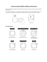
4.6.1. Accessing the Connectors
The VP8800 connectors are beneath a cover on the bottom of the reader.

Page | 9

Page | 10
To access the connectors:
1. Turn over the VP8800 so that the connector cover is visible.
2. Remove the cover.
3. Insert the data cable into the HDMI connector and route the cable through the recesses
provided.

Page | 11
4. Replace the cover.
5. Turn the VP8800 keypad right side up.
6. Place the stylus in the holder along the side of the VP8800.
7. Attach the data cable from the VP8800 to the appropriate port on the POS.
8. Plug in the power supply. The left LED illuminates.
Note: The VP8800 may take up to 30 seconds to finish booting.
The VP8800 displays the opening set of screens before it displays the Welcome screen. The opening
screens include:
• ViVOpay logo screen
• Copyright screen
• Firmware version screen
It should then display Welcome or Please present card or similar wording, depending upon the

Page | 12
POS application.
If the unit fails to power up, try reseating the power connector (or change to a different power outlet). If
the unit still fails to power up, try replacing the power supply. If the unit still fails to power up, and
the power supply is definitely good, contact your local support representative. For more troubleshooting
information, see Troubleshooting and Maintenance below.
4.7. Key Replacement
Cryptographic keys can always be replaced by sending the unit back to the manufacturer if necessary (ID
TECH is a certified Key Injection Facility). ID TECH also provides several choices for users who need to
rotate or replace a cryptographic key in the field:
1. PKI-RKI Client utility, which can replace keys in the field. It requires an internet connection and a
host computer.
2. ID TECH's Universal SDK has the RKI API built in. With proper software, a key can be updated
programmatically via API (this also requires an internet connection).
3. ID TECH can provide PKI-RKI integration instructions; in this case, the integrator implements the
ID TECH RKI feature within custom software.
4.8. Loss or theft
Report the serial number of any lost or stolen product to the vendor from whom it was obtained.
4.9. Testing the Installation
After completing the installation and checking for PCI conformance, run the Onboard Diagnostic
program as described in Onboard Diagnostics. Then check that the VP8800 and the POS are
communicating correctly by performing a sample transaction. The following test assumes that the host
POS is already programmed to communicate with the VP8800.
4.9.1. Transaction Test
The exact wording that appears on the VP8800 screen will depend on the POS application. Consult the
documentation for your POS (or payment app) for details.
4.9.2. LED Behavior
• Solid blue light: Waiting for card presentation.
• Solid green light (with one long beep): Successful card presentation.
• Solid red (with two short beeps): Unsuccessful card presentation.
4.9.3. To test a transaction
Follow the steps below to test a transaction:
1. Begin a transaction on the POS. Present a card, fob, or phone in close proximity to the reader or
swipe a magnetic stripe card.
2. A single beep and LED flash indicates that the card has been validated. The VP8800 may display
“Processing” or similar wording while the transaction is being processed.
3. If the POS software requires a PIN entry, the screen displays “Please enter PIN”. Use the keypad
to enter the PIN.

Page | 13
4. If the POS application requires a signature, the screen displays “Please sign below”. Use the
stylus to enter a signature on the touch screen.
5. A receipt is printed by the POS with the purchase amount. The VP8800 may show “Thank You”
or similar wording for a successful transaction.
5. Decommissioning SRED Devices
All PCI devices require proper decommissioning prior to device disposal in order to ensure the
protection of all sensitive financial card data. For instructions on decommissioning your device, see
Decommissioning of SRED Devices on the ID TECH Knowledge Base.

Page | 14
6. Troubleshooting and Maintenance
The VP8800 is designed for reliability and ease of troubleshooting. The components that may require
troubleshooting include the power supply, the reader, and the data cable.
Symptom
Possible Cause
Probable Cause and Remedy
General Issues
Reader does not appear to be
powered on—no LEDs lit, no LCD
display.
•
Reader not powered on.
• Incorrect power supply used.
•
Check cable connections.
• Verify that power is on and correct
voltage and current are present.
• Replace the power supply.
• Verify that power cable plug is fully
inserted.
• Replace the power supply.
• Replace the reader.
Reading Cards/Fobs/Phones
LEDs do not light up, and beeper
is not audible when card, fob, or
phone is presented.
• Card/fob/phone not properly
presented.
• Metal or RF interference.
• Wrong Firmware issue (contact
your local support representative).
• Reader not powered on or
incorrect voltage.
• Incorrect power supply used.
• Unsupported card, fob, or phone
used.
• Present card, fob, or phone closer to
the reader and ensure it’s parallel to
the reader touch screen.
• Verify that the card, fob, or phone is
valid/current.
• Test with “ViVOcard Contactless Test
Card” P/N241-0015-03.
• Try a different card, fob, or phone.
• Verify that the unit is not near any
large metal objects.
• Verify that correct firmware is loaded
(local support representative only).
• Verify that power is on and correct
voltage and current are present.
• Verify that power cable plug is fully
inserted.
• Replace the reader.
Some cards/fobs/phones read,
but not all.
•
Wrong firmware (contact your
local support representative).
• Possible bad card, fob, or phone.
• Unsupported card used.
•
Verify that correct firmware is loaded
on reader (local support
representative only).
• Check to see if card, fob, or phone is
damaged.
• Try a different card, fob, or phone.
On power-up, display sticks on
firmware version.
•
SAM card isn’t seated properly.
•
Remove power from unit, remove
back cover and reseat SAM card. If
unsure, contact ID TECH Support for
assistance.

Page | 15
Symptom
Possible Cause
Probable Cause and Remedy
Communication to POS/ECR
No data is received, or data is
garbled.
• Faulty or incorrect cable
connections.
• Unsupported card used.
• Contactless application is not
installed on terminal (for serial
connections only).
• Magstripe card not swiped
correctly.
• Magstripe card not level during
card swipe.
• The POS application is not using
the correct communications
parameters.
• Check that the cable connection is
secure and in the correct port on the
POS/ECR.
• Check that the POS/ECR has the
correct software application to accept
data from the contactless reader (may
need assistance from the POS
vendor).
• Try a different card, fob, or phone or
magstripe card if testing the
magstripe reader.
• If testing with the magstripe card, try
turning the card around; make sure
that the card is level during the card
swipe.
• Contact the payment processor for an
application upgrade.
• Check that the cable is correctly
attached to the back of the VP8800.
•
Check the POS application.
6.1. Onboard Diagnostics
Onboard diagnostics (OBD) are available to test the following components of the VP8800.
Test
Possible Results
LCD Test
Pass/Fail
TouchScreen Test
Pass/Fail
Keypad Test
Pass/Fail 1234567890<cancel><backspace><enter>* #
LEDs Test
Pass/Fail virtual LEDs MSR ICC Keypad backlight
Tone Test
Pass/Fail
Magstripe Test
Pass Tracks 1 or 2 or 3/Fail
RFID Test
Pass Type A or B/Fail
ICC Test
Pass T = 0 or T = 1/Fail
Ethernet Test
Pass/Fail
SAMs Test
Pass SAM1 SAM2 SAM3/Fail
6.2. Accessing the Onboard Diagnostic Tests
To enter the onboard diagnostics:
1. Power off the VP8800 by removing the power supply from the power receptacle.
2. Plug the power supply into the power receptacle again.
3. After applying power, press the 1 key and then the # key within three seconds after the LCD
screen displays "Welcome". When entered correctly, The ViVOpay AR Diagnostics screen
appears and the prompt alarm sounds.

Page | 16
The menu’s first page appears as below:
ViVOpay AR Diagnostics
0 Test Results Summary
1 Test Al l
2 LCD
3 Touch Screen
4 Keypad
5 LEDs
6 Tone
7 Magstripe
8 RFID and Antenna
9 ICC
O: Next Page X: Exit
The menu’s second page appears as below:
ViVOpay AR Diagnostics
0 Ethernet
1 SAMs
<: Prev Page X: Exit

Page | 17
6.3. Maintenance
The VP8800 contains no user-serviceable parts within its enclosure. Do not open the VP8800 main
enclosure.
WARNING: Attempting to open the VP8800 enclosure will trigger PCI security measures and the unit
will stop functioning even after reassembly, requiring its return to the factory.
It is possible to replace the stylus without violating PCI security measures. It is also possible to upgrade
the VP8800 firmware if required.
6.3.1. Replacing the Stylus
It is important that only the stylus be used for writing on the touch screen. If the stylus is lost or the
lanyard broken, obtain a replacement from your VP8800 distributor.
To replace the stylus:
1. Turn the VP8800 upside down and unscrew the screw for the tether wire of stylus.
2. Replace the old stylus with the new one. Then fasten the screw.
3. Turn the VP8800 back and place the new stylus in its holder.
6.4. Upgrading Firmware
VP8800 firmware is upgradable, if required for applications. Upgrade firmware using the ID TECH USDK
Demo, which is available for free. Obtain the following from your VP8800 distributor:
• Firmware for the VP8800
• USB data cable
Firmware upgrades also require a PC with a USB port. The PC will likely already have the required USB
driver HID.DLL file. If not, download that file from Microsoft’s website.
To upgrade the firmware:
1. Install and run the USDK Demo.
2. Extract the firmware ZIP file to a directory of your choice.


Page | 19
5. Click Execute Command.
6. A File Explorer window will open; navigate to the directory where you extracted the firmware
ZIP, then open images_for_VLoader >pisces_signed_r25680.bin.
7. Wait for the USDK Demo to complete the firmware update.
8. After the USDK Demo applies the firmware, the VP8800 will reboot and validate the firmware
file. Please note that this can take up to five minutes to complete.
After restarting, the VP8800 will have updated firmware and display its Welcome screen.
7. Appendix A: Specifications
VP8800 Specifications
RF Interface
Frequency
13.56 MHz
Standard
ISO 14443 Type A&B, Mifare, ISO 18092
Reading distance
MAX 4cm
Physical
Length
175 mm
Width
95 mm maximum
Depth
58 mm maximum
Weight
0.4Kg
Storage
128 MB RAM + 64MB Flash + 32GB of Micro-SD, with 3 SAM slots
Environmental
Operating Temp.
0 to 55° C (32 to 131° F)
Storage Temp.
-25 to 65° C (-13 to 149° F)
Relative Humidity
10 to 95% non-condensing
Operating Environment
Indoor only
Power
Voltage
5 VDC regulated, +/- 10%
Consumption
6 W maximum
Power supply
The VP8800 shall be powered by an external power source (P/N AC005R)
(power-pack AC 85-265)
Touch Screen
LCD
Capacitive 3.5” TN TFT Backlit Color Display
Signature Capture
Yes
Resolution
HVGA 480X320 Pixels

Page | 20
Glass Hardness Rating
7H
Power supply
The VP8800 is powered by an external 5VDC power source (P/N AC005R)
(power-pack AC 85-265)
/