Page is loading ...

1
TM
9049 Tyler Blvd. • Mentor, Ohio 44060
Phone (440) 974-8888 • Fax (440) 974-0165
Toll-Free Fax 800-841-8003 • saltdogg.com
Installation Instructions
TGS07 Salt Spreader
TGS07RED Salt Spreader
TGS07YEL Salt Spreader
US PATENT 8,888,025; 9,562,333
other PATENTS PENDING
Serial Number 01700 and Higher
—continued inside
WARNING
Observe the following Safety Precautions before,
during and after operating this spreader. By following these
precautions and common sense, possible injury
to persons and potential damage to this machine may be
avoided.
SPREADER WARRANTY
This warranty replaces all previous warranties and
no employee of this company is authorized to extend
additional warranties, or agreements, or implications not
explicitly covered herein.
Buyers Products Company warrants all parts of
the product to be free from defects in material and
workmanship for a period of one (1) year. Parts must be
properly installed and used under normal conditions.
Normal wear is excluded.
Any part, which has been altered, including modifications,
misuse, accident, or lack of maintenance will not be
considered under this warranty.
The sole responsibility of Buyers Products Company
under this warranty is limited to repairing or replacing any
part(s), which are returned, prepaid, 30 days after such
defect is discovered, and returned part(s) are found to be
defective by Buyers Products Company.
Authorization from Buyers Products Company must
be obtained before returning any part. The following
information must accompany defective parts returned
to Buyers Products Company: RMA #, spreader model,
serial number, date installed, and distributor from whom
purchased.
Buyers Products Company shall not be liable for damage
arising out of failure of any unit to operate properly,
or failure, or delay in work, or for any consequential
damages. No charges for transportation or labor
performed on any part will be allowed under this warranty.
Safety Precautions
1. Read this entire Installation Instruction before oper-
ating this spreader.
2. Read all safety decals on the spreader before
operating.
3. Verify that all personnel are clear of the
spreader spray area before starting or operating this
spreader.
4. Do not adjust, clean, lubricate or unclog material
jams without first turning off the spreader.
5. Make sure the spreader is securely fastened to the
vehicle in accordance with this manual.
6. Do not operate a spreader that is in need of mainte-
nance or repairs.
7. Always disconnect the battery before removing or
replacing electrical components.
Spreader Assembly
Check contents of box against parts list to make sure
all components are included. When ordering replace-
ment or spare parts refer to parts list for part numbers.

2
TM
1. Slide frame #3015859 into hitch receiver. Fig.1.
2. Slide hopper assembly #3015380 between frame
uprights with front portion rested on the truck’s bumper.
Fig.2.
Fig. 1
Fig. 2

3
TM
WARNING
SPREADER CANNOT BE SUPPORTED BY FRAME ONLY!
SPREADER HOPPER MUST REST ON BUMPER OR SIMILAR
STRUCTURE ATTACHED TO TRUCK FRAME.
Fig. 3
Fig. 6
3. Align holes in rear portion of the hopper with slots
in frame uprights. Use slots which will position spreader
with a slight upward tilt. Secure hopper assembly to frame
using ½-13 x 3.0 screws, flat washers and nuts. Fig.3. Do
not tighten fasteners at this time.
4. Slide hopper and frame towards tailgate leaving about
3/8” to ½” space. Align closest holes in hitch receiver with
holes in frame. Secure frame in hitch receiver using 5/8
hitch pin and cotter pin. Fig.4.
5. Assembly ½-13 x 6.0 screws with flat washers and ½-13
flanged nuts and nylock nuts as shown in Fig.5. Make sure
that nuts located between hopper side brackets and frame
positioned exactly as shown. These nuts must not be in
contact with brackets and frame at this time.
6. Tighten nuts located under frame evenly on both sides
of the spreader (10-15 ft-lb’s. torque). Then
tighten bolts in frame uprights. Finally tighten nuts located
between hopper side brackets and frame.
They must look as shown in Fig.6. After this procedure
spreader should be securely attached to trucks bumper
and frame.
1/2-13 X 3.0 SCREW
1/2 FLAT WASHER
1/2-13 NYLOCK NUT
SCREW 1/2-13 X 6.0
NUT 1/2-13 FLANGED
WASHER 1/2 FLAT
NYLOCK NUT 1/2-13
HITCH PIN
COTTER PIN
Fig. 4
Fig. 5

4
TM
SCREW 3/8-16 x 2.0
3018923
SPINNER
PROTECTOR
WASHER FLAT 3/8
NUT 3/8-16
3015926
HINGE LID
SCREW 3/8-16 X 1.0
WASHER FLAT 3/8
NUT NYLOCK 3/8-16
SHIELD #3015707
8. Attach spinner protector #3018923 to spreader frame as
shown in Fig.8.
7. Attach shield #3015707 to trough bracket as shown in
Fig.7
Fig. 8
Fig. 10
9. Attach spinner disk to gear motor shaft as shown in Fig.9.
Secure disk on shaft using clevis pin and cotter pin.
Fig. 7
3019561
CLEVIS PIN 1420014
COTTER PIN FPC007800075
Fig. 9
10. Install lid #3015926 on to hopper. Place lid on hopper.
Bend hinges outward from center of the hopper. Slide
hinges openings on round protrusions of the lid. Repeat
this operation on opposite side of the hopper. Secure lid on
hopper using lynch pin.
To open lid from ether side of the hopper disengage lynch
pin, bend both hinges outwards and open lid.

5
TM
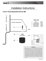
Installing Controller and Wiring
• Route both wire harnesses into truck cab through firewall
(it maybe necessary to drill holes). Insulate hole to avoid
water leaks.
• Insure no wires are nicked or damaged during installation.
• Connect the 4-pin connecter on the wire harness to the
control box.
• Connect the 2-pin connector on the power cable to the
control box.
• Lay out a path for the power cable to the battery, use
quick ties to secure power cable.
DO NOT CONNECT TO BATTERY AT THIS TIME!
• Lay out path for wire harness to the rear of the vehicle.
It is recommended to stay clear of the exhaust system.
Excess heat can damage the wire harnesses. Use quick
ties to secure harness to underbody.
• Connect the wire harness to the motor and vibrator.
• Connect the power and ground cables directly to the
battery.
• Insure all functions of the controller are working properly.
• Note: direction of spinner may be changed by inter
-
changing the motor leads.
THIS IS WIRE GROUND ELECTRICAL SYSTEM!
NO CONNECTIONS TO TRUCK’S FRAME OR BODY
ALLOWED!
NOTE: Always disconnect battery before attempting to
install electrical components on your vehicle.
Mount the controller in a convenient location in the truck
cab. It is recommended not to mount the controller directly
in front of heat vents. Allow ample air space around
controller.
CAUTION
DO NOT MOUNT CONTROLLER IN THE WAY OF AIR BAG
DEPLOYMENT!
3011864
3008620
3035934
CB50PB
3001379
BATTERY POSITIVE
BATTERY NEGATIVE

6
TM
Spreader Operation.
1. Due to the rate at which materials absorb moisture dif-
ferently, some materials may not perform as desired.
Therefore, the substitution of an alternative material may
be necessary for optimum performance.
2. When filling hopper use supplied screen to prevent large
chunks of material and debris contained in the material
to get into hopper and cause operational problem or
damage.
3. Material must never be left in the hopper for extended
period of time. Material will absorb moisture, bind, hard
-
en and may prevent spreader from proper operation or
may damage the spreader.
4. To start spreader make sure that truck engine is running.
Flip POWER switch in ON position. Switch will illuminate.
Spreader motor will accelerate to full speed and then it
will slow down to previously dialed speed.
5. To adjust material flow rate and spreading distance, sim
-
ply rotate speed knob to desired speed. Spreader can
be put in full speed mode for short time by pressing and
holding BLAST button.
6. To activate and deactivate vibrator press VIBRATOR
button.
7. In addition material flow rate can be controlled by adjust
-
ing inverted vee, located inside hopper. To reduce mate-
rial flow, lower inverted vee towards auger. For slow and
difficult to flow materials inverted vee can be raised or
completely removed.
8. In addition, material flow and pattern can be adjusted
by opening/ close adjustable discharge on the trough
bottom.
Controller Warnings.
Check controller instruction sheet for latest controller
updates, troubleshooting codes. Controller instruction sheet
is inside controller shipping box.
IMPORTANT! INSTALLER, DO NOT DISCARD
CONTROLLER INSTRUCTION SHEET. STAPLE SHEET
TO SPREADER MANUAL AND GIVE TO END USER!
Maintenance Instructions.
1. Wash spreader after every use. Make sure no material
left under auger and/or inside trough.
2. Inspect and retighten fasteners after every 5-7 hours of
operation.
3. Lubricate bearing every 7-10 hours of operation using
general automotive grease.
4. Inspect terminals/ connectors every time you disconnect
spreader from wire harness. Apply thin layer of dielectric
grease on terminals. If any tarnish/corrosion found, clean
terminals and apply dielectric grease.
End of Season Maintenance.
1. Wash spreader. Make sure no material or residue left in
and outside hopper.
2. Lubricate bearing using general automotive grease.
3. Inspect wire harness, connectors for broken insulation,
missing components. Replace if necessary.
4. Apply dielectric grease on all electrical connectors.
5. Store hopper indoors, in dry, cool place.
6. Inspect, clean and repaint frame.
7. Remove controller from truck. Store controller indoors, in
dry, cool place.

7
TM
1
2
3 4
5
6
7
8
9
10
11
12
13
14
15
16
17
18
19
20
1
2
4
5
3
6
7
8
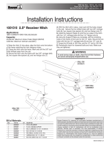
Tailgate Auger
TGS07 Hopper Assembly
ITEM PART NO. QTY. DESCRIPTION
1
3015380 1 HOPPER ASSEMBLY, TGS07
3026561 1 HOPPER ASSEMBLY, RED
3026563 1 HOPPER ASSEMBLY, YELLOW
2 3015859 1 FRAME, HITCH MOUNT
3 3020207 1 HARDWARE BOX TGS07
4
3015926 1 LID, TGS07
3026566 1 LID, RED
3026567 1 LID, YELLOW
5 3015707 1 SHIELD TGS07
6 3019561 1 SPINNER, 12 IN TGS
7 3018923 1 DISC PROTECTOR
8 3018781 1 SCREEN TGS07
Bill of Materials
ITEM PART NO. QT Y. DESCRIPTION
1
3015379 1 HOPPER TGS07
3026560 1 HOPPER, RED
3026562 1 HOPPER, YELLOW
2 3015383 1 TROUGH ASSEMBLY TGS07
3 FWF031075006SS 6 WASHER, 5/16 SAE SST
4 3006721 6 SCREW, HEX HD, 5/16-18 X 3/4 GR5 S
5 3007416 1 VIBRATOR 200 LBS 12 VDC
6 3017030 1 RETAINER, VIBRATOR
7 3017028 10 BOLT, CRG, 3/8-16x3.25 SST
8 3016021 4 HINGE, LID TGS07
9 3016983 8 RETAINER, HINGE
10 3015925 14 SCREW #14X1.25 SST
11 3015694 1 MOTOR COVER TGS07
12 3016670 2 BRACKET DRAW, WELDMENT
13 3017029 2 RETAINER, DRAW BRACKET
14 FNE038016044SS 10 NUT, NYLOCK 3/8-16 X 7/16 SST
15 3016979 2 PIN, 3/16 LYNCH
16 4375 2 CLAMP, HOSE .4375, 9/32 HOLE
17 3017984 1 CAP ROUND 1.312 ID VINYL BLACK
18 3018773 1 BAFFLE WELDMENT TGS07
19 3018922 1 RETAINER, BAFFLE
20 3007115 2 WASHER, FLAT 3/8 X 1.5 X.048 SST
Bill of Materials

8
TM
2
3
4
5
6
7
8
9
10
11
12
13
14
15
16
17
19
18
1
ITEM PART NO. QT Y. DESCRIPTION
1 3015377 1
GEAR MOTOR DUAL SHAFT .5
HP 12 VDC
2 3015381 1
TROUGH WELDMENT, TGS07
3 3015382 1
AUGER TGS07
4 1411000 1
BEARING, 2-HOLE FLANGED 1"
5 FWF031075006SS 4
WASHER, 5/16 SAE SST
6 3006721 4
SCREW, HEX HD, 5/16-18 X 3/4
GR5 SS
7 FPY031000150 1
PIN, CLEVIS, 5/16 X 1-1/2, W/
5/32 PH, ZN
8 3014994 1
PIN,COTTER,1/8IN X 1IN SST
9 FNE038016044SS 4
NUT, NYLOCK 3/8-16 X 7/16
SST
10 3019374 1
DISCHARGE, ADJUSTABLE
11 3012144 1
BOLT, RHSQN,.25-20X.5 SST
12 FWF038100007SS 2
WASHER, FLAT 3/8 USS SST
13 FCS038016075SS 2
SCREW, HHC-3/8-16 X 3/4 SST
14 FWF025063007SS 1
WASHER, FLAT 1/4 SAE SS
15 3016751 1
NUT,WING 1/4-20 SST
1
2
3
4
5
6
7
8
9
10
11
12
13
14
15
9049 Tyler Blvd. • Mentor, Ohio 44060
Phone (440) 974-8888 • Fax (440) 974-0165
Toll-Free Fax 800-841-8003 • saltdogg.com
3020208_D
TGS07 Trough Assembly
TGS07 Hardware Box
Bill of Materials
Bill of Materials
ITEM PART NO. QT Y. DESCRIPTION
1 3011864 1 CONTROLLER TGS W/ VIBRATOR SWITCH
2 3035934 1 WIRE HARNESS, POWER TGS
3 3008620 1 WIRE HARNESS MAIN W/ VIBRATOR, TGS
4 3017039 2
SCREW, HEX HEAD CAP 1/2-13 X 6.00 SST
FULL THREAD
5 3035934 4 NUT, HX FLNG-1/2-13 SST
6 3000269 10 WASHER, FLAT 1/2 USS, SST
7 3001250 4 SCREW, HHC-1/2-13 X 3 SST
8 FNE050013053SS 6 NUT, NYLOCK 1/2-13 SS
9 1420014 1 PIN CLEVIS, 1/4 X 2.5
10 FPC007800075 1 COTTER PIN, 5/64 X 3/4
ITEM PART NO. QT Y. DESCRIPTION
11 FWF038100007 4 WASHER, FLAT 3/8 USS ZINC
12 FNE038016044 4 NUT, NYLOCK 3/8-16 X 7/16 ZINC
13 FWF038100007SS 4 WASHER, FLAT 3/8 USS SST
14 FCS038016100SS 2 SCREW, HHC 3/8-16 X 1 304 SST
15 FNE038016044SS 2 NUT, NYLOCK 3/8-16 X 7/16 SST
16 HP6253WC1 1 PIN, 5/8 HITCH
17 HP12 1 PIN, HAIR COTTER 5/32” ZN 3.25 OAL
18 3001379 1 BATTERY CABLE
19 FCS038016200 4 SCREW, HHC 3/8-16 X 2 GR 5 ZP
3018421 1 ANTI SEIZE LUBRICANT POUCH 5 GRAMM
CB50PB 1 CIRCUIT BREAKER
/