Page is loading ...

1
TM
9049 Tyler Blvd. • Mentor, Ohio 44060
Phone (440) 974-8888 • Fax (440) 974-0165
Toll-Free Fax 800-841-8003 • saltdogg.com
Installation Instructions
TGS06 Salt Spreader
—continued inside
WARNING
Observe the following Safety Precautions before, during
and after operating this spreader. By following these pre-
cautions and common sense, possible injury to persons
and potential damage to this machine may be avoided.
SPREADER WARRANTY
This warranty replaces all previous warranties and no
employee of this company is authorized to extend addi-
tional warranties, or agreements, or implications not
explicitly covered herein.
Buyers Products Company warrants all parts of the
product to be free from defects in material and workman-
ship for a period of one (1) year. Parts must be properly
installed and used under normal conditions. Normal wear
is excluded.
Any part, which has been altered, including modifica-
tions, misuse, accident, or lack of maintenance will not
be considered under this warranty.
The sole responsibility of Buyers Products Company
under this warranty is limited to repairing or replacing any
part(s), which are returned, prepaid, 30 days after such
defect is discovered, and returned part(s) are found to be
defective by Buyers Products Company.
Authorization from Buyers Products Company must
be obtained before returning any part. The following
information must accompany defective parts returned
to Buyers Products Company: RMA #, spreader model,
serial number, date installed, and distributor from whom
purchased.
Buyers Products Company shall not be liable for damage
arising out of failure of any unit to operate properly, or
failure, or delay in work, or for any consequential dam-
ages. No charges for transportation or labor performed
on any part will be allowed under this warranty.
Safety Precautions
1. Read this entire Installation Instruction before oper-
ating this spreader.
2. Read all safety decals on the spreader before
operating.
3. Verify that all personnel are clear of the spreader
spray area before starting or operating this spreader.
4. Do not adjust, clean, lubricate or unclog material
jams without first turning off the spreader.
5. Make sure the spreader is securely fastened to the
vehicle in accordance with this manual.
6. Do not operate a spreader that is in need of main-
tenance or repairs.
7. Always disconnect the battery before removing or
replacing electrical components.
Spreader Assembly
Check contents of box against parts list to make sure
all components are included. When ordering replace-
ment or spare parts refer to parts list
(figures 8 and 9) for part numbers.

2
TM
39
40
28
40
41
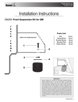
1. Assemble and install Hitch Adjuster to
spreader assembly. Refer to Fig. 1.
• Insert and align hitch adjuster 28 between mounting
brackets as shown.
• Assemble hardware (2) 1/2"-13 x 3.5" bolts 39,
(4) 1/2" washers 40, and (2) 1/2"-12 jam nuts 41.
• Hand tighten hardware at this time.
Fig. 1

3
TM
27
38
37
42
43
27
43
44
Fig. 2A
Fig. 2B
2. Assemble and install Hitch Receiver to Vehicle
Option A (hitch assembly) suggested
Refer to Fig. 2A
• Insert hitch receiver 27 into hitch of vehicle as shown with
slots in vertical tube portion pointing towards the ground. Select
one of the three mounting holes, insuring opening in vertical
tube is not obstructed by bumper.
• Insert hitch pin 37 and secure with cotter pin 38.
• This mounting hole location may change later in the assembly.
Option B (bumper assembly) Refer to Fig. 2B
• Align hitch receiver 27 with precut hole (ball mount hole)
on factory bumper with slots in vertical tube portion pointing
towards the ground. Slide vehicle tube as close to bumper as
possible.
Note: On some vehicles the bumper may have a plastic liner
covering the bumper and ball mount hole. In this situation, the
plastic liner may need to be cut to gain access to ball mount
hole.
• Insert hardware, (1) 5/8"-11 x 5" bolt 42, (2) 5/8" washers 43,
and (1) 5/8"-11 nut 44.
• Hand tighten hardware at this time.

4
TM
36
32
35
34
3. Assemble Stake Pocket Mounts Refer to Fig. 3
• Assemble two stake pocket mounts as shown using (1) cover
plate 32, (1) retainer nut plate 34, (1) retainer plate 35, and (1)
3/8"-16 x 2½" bolt 36.
• Insure “U” portion of retainer plate is facing up, or towards
cover plate.
• Thread bolt into retainer nut plate using 2-2½ turns. This bolt
will be tightened once inserted into stake pocket
of truck.
Fig. 3
4. Insert Stake Pocket Mounts Refer to Fig. 4
• Install assemblies into stake pockets with the empty holes
towards the tailgate of the vehicle.
Fig. 4
• Insure “U” portion of the retainer plate securely engages sheet
metal of truck bed.
• Hand tighten hardware only.

5
TM
26
36
33
5. Install Spreader Assembly to Vehicle
Refer to Fig. 5
• Lift and align the spreader so that the adjuster hitch aligns
with the hitch receiver. Allow spreader to rest on hitch receiver
and bumper of vehicle. It may be necessary for two people to
perform the lifting of the spreader.
Fig. 5
Fig. 6
6. Install Stake Pocket Straps Refer to Fig. 6
• Insert (2) stake pocket straps 26 into holes located in
spreader.
• Rotate straps until aligned with empty holes on stake pocket
covers. You may need to pull the spreader towards the tailgate
to align straps to the best suited hole.
• Insert (2) 3/8"-16 x 2½" bolts 36 and (2) spacers 33 as shown.
• Hand tighten hardware only.
• Adjust spreader location for best fit. Tighten all hardware.
Check all fasteners periodically to ensure they are tight.

6
TM
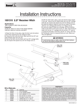
7. Installing Controller and Wiring Diagram
Refer to Fig 7.
• NOTE: Always disconnect battery before attempting to
install electrical components on your vehicle.
• Mount the controller in a convenient location in the truck cab.
It is recommended not to mount the controller directly in front of
heat vents.
• Route both wire harnesses into truck cab through firewall (it
maybe necessary to drill holes). Insulate hole to avoid water
leaks.
• Insure no wires are nicked or damaged during installation.
• Connect the 4-pin connecter on the wire harness to the con-
trol box.
• Connect the 2-pin connector on the power cable to the control
box.
• Lay out a path for the power cable to the battery, use quick
ties to secure power cable. DO NOT CONNECT TO BATTERY
AT THIS TIME!
• Lay out path for wire harness to the rear of the vehicle. It is
recommended to stay clear of the exhaust system. Excess heat
can damage the wire harnesses. Use quick ties to secure har-
ness to underbody.
• Connect the wire harness to the motor and vibrator located
inside the TGS06 spreader.
• Connect the power and ground cables directly to the battery
(Fig 7).
• Insure all functions of the controller are working properly.
• Note: direction of spinner may be changed by interchanging
the motor leads.
8. Operating Instructions
• Ensure flow gate is in closed position.
• Caution: when filling hopper, make certain there are no large
objects contained in the material which could cause the spinner
to bind and stop operation of the spreader motor.
• Fill hopper with #1 rock salt or calcium chloride from bags. DO
NOT USE BULK MATERIAL. All material must have the same
crystal size as #1 rock salt.
• Slide flow gate to desired opening for material flow.
• NOTE: Different materials will have different flow rates.
9. Maintenance Instructions
• Occasionally inspect spreader for loose bolts and nuts.
• Inspect for broken wires, frayed or cracked insulation.
• Always remove salt from spreader after each use, if salt is
not removed, it will harden and no longer flow and stop normal
operation.
• Inspect and clean flow gate and matting surfaces to remove
any unwanted rock salt.
3011864
3008620
3035934
CB50PB
3001379
BATTERY POSITIVE
BATTERY NEGATIVE
Fig. 7

7
TM
1
2
3
4
5
6
7
8
9
10
11
12
13
14
15
16
17
18
19
20
21
22
23
24
25
12
15
12
12
15
13
12
14
13
12
12
14
12
14
(Inside
Hopper)
(Inside
Hopper)
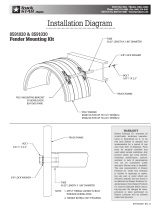
Bill of Materials
1 3010963 1 Hopper TGS06
2 3010965 1 Bumper TGS06
3 3009320 1 Motor, 12 VDC, 1000 RPM, 1/8 HP
4 3009323 1 Flowgate
5 3009404 1 Handle Hold Down
6 3009874 1 Plate Mounting
7 3009311 2 Mounting Bracket Hitch
8 3008076 1 Vibrator 80 lbs. 12 VDC
9 3009312 1 Plate Cover
10 3008043 2 Plate Vibrator Kit SST
11 3010966 1 Shield TGS06
12 – 40 Washer, Flat 3/8 USS SST
13 – 11 Cap Screw, Hex HD-38-16 x 3 SST
ITEM PART NO. QTY. DESCRIPTION
14 – 21 Nut, Nylock 3/8-16 x 7/16 SST
15 – 13 Screw, Hex HD Cap 3/8-16 x 1½ SST
16 – 4 Washer, 1/4" Split Lock SST
17 – 4 Screw Cap 1/4-20 x 3/4 SST
18 – 4
Screw, Sheet Metal #12x1.0 Hex Washer HD
19 3009319 2 Pin, Pivot Lid
20 3009324 2 Spring Pin Lid
21 3009317 3 Spring Gate TGS06
22 3010970 1 Spinner Poly TGS06
23 1420014 1 Pin Clevis, 1/4 x 2.5
24 – 1 Cotter Pin, 5/64 x 3/4
25 3010964 1 Lid TGS06
ITEM PART NO. QTY. DESCRIPTION
Fig. 8
BOM Hopper Assembly

8
TM
9049 Tyler Blvd. • Mentor, Ohio 44060
Phone (440) 974-8888 • Fax (440) 974-0165
Toll-Free Fax 800-841-8003 • saltdogg.com
3010971_C
Bill of Materials
1 3009906 2 Assembly Stake Pocket Straps
2 3009872 1 Assembly Hitch Receiver
3 3009873 1 Adjuster, Hitch
4 3011864 1 Controller TGS w/Vibrator
5 3035934 1 Wire Harness, Power TGS
6 3008620 1 Wire Harness Main w/Vibrator TGS
7 3009869 2 Cover Plate, Stake Pocket
8 3010292 2 Spacer, Stake Pocket
9 3007795 2 Retainer Nut Plate
10 3007755 2 Plate Retainer
11 - 4 Screw, HHC 3/8-16 x 2½ Gr 5 Zp
ITEM PART NO. QTY. DESCRIPTION
1
2
3
4
5
6
8
9
10
11
12
13
14
15
16
17
18
19
7
20
12 HP6253WC1 1 Pin, 5/8 Hitch
13 — 1 Pin, Hair Cotter
14 - 3 Screw, HH 1/2-13 x 3.5 Gr 5 Zn
15 - 6 Washer, Flat .500 x 1.38 x .14 Zn
16 - 3 Nut, 1/2-13 Hex Jam Gr 8 Yellow Zinc
17 - 1 Screw, HH Cap 5/8-11 x 5.0 Gr 8 Zn Spcl
18 - 2 Washer, 5/8 SAE Flat Zn
19 - 1 Nut, Hex Nylock 5/8-11 SST
20 3001379 1 Cable Battery
21 CB50PB 1 Circuit Breaker
ITEM PART NO. QTY. DESCRIPTION
Fig. 9
BOM Hardware
/