Page is loading ...

www.buyersproducts.com
Phone (440) 974-8888
Fax 800-841-8003
1801005
Hitch Receiver, Class 4
CHEVY/GMC
• 1988-2000 Classic
• 1999-2006 Silverado / Sierra 1500, 2500
• 1996-2006 Silverado / Sierra 2500HD
DODGE
• 1971-1993 Full size pickup
• 1994-2001 Ram 1500 (drilling required on
short bed)
• 1994-2002 Ram 3500 (drilling required on
short bed)
FORD
• 1973-1996 Full Size Pickups
• 1997-2004 F-150 Old Body Style
• 1997-2006 F-250 / F-350 Super Duty
TOYOTA
• 2000-2006 Tundra
Installation Instructions
CAUTION
Keep debris out of your eyes always wear protective
eyewear. Tighten screws and nuts only when it is
recommended by these instructions. Check contents
of box against part list to make sure all components
are included.
WARNING
Do not lubricate threads; hardware failure may
occur due to overtightening. Do not drill or weld to
this product. Use only Buyers supplied or approved
hardware to install this product.
—continued
1

www.buyersproducts.com
Phone (440) 974-8888
Fax 800-841-8003
Quality since 1946Quality since 1946
1 3004980 1 Middle Section
2 3004908 1 Side Bracket
3 3004909 1 Side Bracket
4 FCS038016125 8 Screw, HHC-3/8-16 x 1.25 Gr 5 Zn
5 FWF038081006 16 Washer, Flat 3/8 SAE Zn
6 FNE038016044 8 Nut, Nylock 3/8-16 x 7/16 Zn
7 3004906 4 3/8" Spacer
ITEM PART NO. QTY. DESCRIPTION
ITEM PART NO. QTY. DESCRIPTION
Bill of Materials
8 3001384 2 Screw, Hex Cap 1/2-13 x 2" Gr 5 Zn
9 FWF050106010 4 Washer, Flat 1/2" SAE Zn
10 FNE050013053 2 Nut, Nylock 1/2-13 Zn
11 3004907 2 Bolt Plate, 1/4"
12 FWL050 2 Lockwasher, 1/2"
13 3005063 2 Screw M12-1.75 x 80 mm HH Class 10.9 Zn
14 3005078 2 Plug, 7/16" Dia. Poly
Tools Required
•1/2" drill bit •3/4" socket •3/4" wrench
•9/16" socket •9/16" wrench •19 mm wrench
•19 mm socket •15 mm wrench
•15 mm socket •Torque wrench
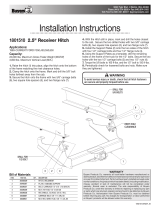
1. Remove and discard the 12 mm diameter bolts at end of
frame. Some vehicles have 8 mm diameter bolt on passenger’s
side. Remove that bolt and reinstall it with the head on bottom
of frame.
2. If your vehicle has rivets on bottom of frame, you will need
to install one 3/8" thick spacer between frame and bracket at
each bolting location. Do not bolt brackets directly against
rivets.
3. Using supplied 12 mm screws, 1/2" flat washers and lock
washers, fasten brackets to frame where the 12 mm factory
bolts were removed. See diagram. For short beds use hole 2.
For long beds use hole 1. Some dual pipe exhaust systems
will hit the bracket. Exhaust will need to be modified.
4. Short beds. Insert 1/2" screws with l/4" plates down
through 1" diameter holes in frame and into holes (4) in bracket.
Install 1/2" washers and lock nuts on each screw. Leave nuts
loose at this time.
5. Long beds. Insert 1/2" screws with l/4" plates down
through 1" diameter holes in frame and into holes (3) in bracket.
(On some models the forward holes may be 1/2".) Install 1/2"
washers and lock nuts on each screw. Leave nuts loose at this
time.
6. Place middle section between brackets as shown. Spare
tire may need to be loosened. Attach middle section using 3/8"
screws, washers and lock nuts. Be sure to use four holes to
bolt side brackets to middle section.
7. Tighten nuts in the following order: First torque 3/8" nuts to
40 ft-lb. Then torque 1/2" nuts to 70 ft-lb.
8. Retighten spare tire if it was loosened.
9. Be sure that spare tire is not rubbing against brake hose. If
needed, bend the brake hose bracket so that you have clear-
ance between tire and brake hose.
10. Install plastic plugs into 3/8" holes in middle section.
1801005 Hitch Receiver, Class 4
1988-2000– Chevy & GMC (Classic)
—continued
10

www.buyersproducts.com
Phone (440) 974-8888
Fax 800-841-8003
Quality since 1946Quality since 1946
Tools Required:
• 3/4" Socket
• 3/4" Wrench
• 9/16" Socket
• 9/16" Wrench
• 21 mm Socket
• Torque Wrench
1. Remove 14 mm bolts from bottom of frame with
a 21 mm socket.
2. Bolt brackets on with 14 mm bolts that were just
removed into the holes as shown. Insert 1/2" screw
with 1/4" plate through large hole in frame and into
brackets as shown. Install 1/2" washers and lock
nuts on the bolts. Leave nuts loose at this time.
3. Install middle section between the brackets
as shown. Use bolting locations indicated. Attach
middle section using 3/8" screws, washers and lock
nuts. Be sure to use four holes to bolt side brack-
ets to middle section.
4. Tighten nuts in the following order: First torque
the 3/8" nuts to 40 ft-lb. Then torque 1/2" nuts to 70
ft-lb. and 14 mm bolts to 85 ft-lb.
1 3004980 1 Middle Section
2 3004908 1 Side Bracket
3 3004909 1 Side Bracket
4 FCS038016125 8 Screw, HHC-3/8-16 x 1.25 Gr 5 Zn
5 FWF038081006 16 Washer, Flat 3/8 SAE Zn
6 FNE038016044 8 Nut, Nylock 3/8-16 x 7/16 Zn
7 3001384 2 Screw, Hex Cap 1/2-13 x 2" Gr 5 Zn
8 FWF050106010 2 Washer, Flat 1/2" SAE Zn
9 FNE050013053 2 Nut, Nylock 1/2-13 Zn
10 3004907 2 Bolt Plate, 1/4"
ITEM PART NO. QTY. DESCRIPTION
Bill of Materials
1801005 Hitch Receiver, Class 4
1999-2006 – Chevy Silverado & GMC Sierra 1500, 2500
—continued
11

www.buyersproducts.com
Phone (440) 974-8888
Fax 800-841-8003
Quality since 1946
Tools Required:
• 3/4" Socket
• 3/4" Wrench
• 9/16" Socket
• 9/16" Wrench
• Torque Wrench
• 21 mm Socket
1. Remove 14 mm bolts from bottom of frame with
a 21 mm socket.
2. Bolt brackets on with 14 mm bolts that were just
removed into holes as shown. Insert 1/2" screw with
1/4" plate through large hole in frame and into brack-
ets as shown. Install 1/2" washers and lock nuts on
bolts. Leave nuts loose at
this time.
3. Install middle section between brackets as
shown. Use bolting locations indicated. Attach
middle section using 3/8" screws, washers and lock
nuts. Be sure to use four holes to bolt side brack-
ets to middle section.
4. Tighten nuts in the following order: First torque
3/8" nuts to 40 ft-lb. Then torque 1/2" nuts to 70
ft-lb. and 14 mm bolts to 85 ft-lb.
5. Install plastic plugs into 3/8" holes in middle sec-
tion.
1 3004980 1 Middle Section
2 3004908 1 Side Bracket
3 3004909 1 Side Bracket
4 FCS038016125 8 Screw, HHC-3/8-16 x 1.25 Gr 5 Zn
5 FWF038081006 16 Washer, Flat 3/8 SAE Zn
6 FNE038016044 8 Nut, Nylock 3/8-16 x 7/16 Zn
7 3001384 2 Screw, Hex Cap 1/2-13 x 2" Gr 5 Zn
8 FWF050106010 2 Washer, Flat 1/2" SAE Zn
9 FNE050013053 2 Nut, Nylock 1/2-13 Zn
10 3004907 2 Bolt Plate, 1/4"
11 3005078 2 Plug, 7/16" dia. Poly
ITEM PART NO. QTY. DESCRIPTION
Bill of Materials
1801005 Hitch Receiver, Class 4
1996-2006 – Chevy Silverado & GMC Sierra 2500HD
—continued
8

www.buyersproducts.com
Phone (440) 974-8888
Fax 800-841-8003
Quality since 1946
Tools Required:
• 3/4" Socket
• 3/4" Wrench
• 9/16" Socket
• 9/16" Wrench
• Torque Wrench
• 1/2" Drill Bit
1. Insert 1/2" screws with 1/4" plate down through
1" holes at end of frame. Fasten brackets to frame
as shown with 1/2" washers and lock nuts. Leave
nuts loose at this time.
2. Install middle section as shown. Use bolting loca-
tions indicated. Attach middle section using 3/8"
screws, washers and lock nuts. Be sure to use four
holes to bolt side brackets to middle section.
Leave nuts finger tight at this time. Some spare tire
carriers may need to be modified if the receiver hits
tire.
3. Using the most farthest holes in brackets as
a guide, drill 1/2" holes in frame.
4. Insert 1/2" screws with 1/4" plates down through
frame and brackets. Install 1/2" washers and lock
nuts.
5. Tighten nuts in the following order: First torque
3/8" nuts to 40 ft-lb. Then torque 1/2" nuts to 70
ft-lb.
6. Install plastic plugs into 3/8" holes in middle sec-
tion.
1 3004980 1 Middle Section
2 3004908 1 Side Bracket
3 3004909 1 Side Bracket
4 FCS038016125 8 Screw, HHC-3/8-16 x 1.25 Gr 5 Zn
5 FWF038081006 16 Washer, Flat 3/8 SAE Zn
6 FNE038016044 8 Nut, Nylock 3/8-16 x 7/16 Zn
7 3004907 2 Bolt Plate, 1/4"
8 3001384 2 Screw, Hex Cap 1/2-13 x 2" Gr 5 Zn
9 FWF050106010 2 Washer, Flat 1/2" SAE Zn
10 FNE050013053 2 Nut, Nylock 1/2-13 Zn
11 3005078 2 Plug, 7/16" dia. Poly
ITEM PART NO. QTY. DESCRIPTION
Bill of Materials
1801005 Hitch Receiver, Class 4
1971-1993 – Dodge Full Size Pickups
—continued
9

www.buyersproducts.com
Phone (440) 974-8888
Fax 800-841-8003
Quality since 1946
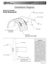
frame as shown in diagram. Install 1/2" screws with 1/4" plates
into holes. Be sure to insert two 3/8" thick spacers between
frame and brackets. Install 1/2" washers and lock nuts.
5. If exhaust hanger was removed, drill 3/8" hole through
hanger and attach it to side bracket in one of the holes provid-
ed in bracket. Use 3/8" hardware provided to reattach exhaust
hanger.
6. Tighten nuts in the following order: First torque 3/8" nuts
to 40 ft-lb. Then torque 1/2" nuts to 70 ft-lb.
7. If spare tire was loosened, retighten it now.
Tools Required:
• 3/4" Socket
• 3/4" Wrench
• 9/16" Socket
• 9/16" Wrench
• Torque Wrench
• 13 mm Socket
• 1/2" Drill Bit
• 3/8" Drill Bit
1. Spare tire may need to be loosened for installation.
2. Bolt brackets to frame with 1/2" screws and 1/4" plates
inserted through 1" holes in end of frame. Install two 3/8" thick
spacers between frame and brackets at rear bolting locations.
Install 1/2" washers and lock nuts. For some models, exhaust
hanger will need to be unbolted from frame.
3. Install middle section between brackets as shown. Use hole
pattern that works best for your truck. Insert 3/8" bolts through
middle section and brackets. Install 3/8" washers and nuts on
screws; finger-tight nuts at this time. Be sure to use four holes
to bolt side brackets to middle section.
4. Using holes in brackets as a guide, drill 1/2" hole through
1 3004980 1 Middle Section
2 3004908 1 Side Bracket
3 3004909 1 Side Bracket
4 FCS038016125 8 Screw, HHC-3/8-16 x 1.25 Gr 5 Zn
5 FWF038081006 16 Washer, Flat 3/8" SAE Zn
6 FNE038016044 8 Nut, Nylock 3/8-16 x 7/16 Zn
7 3004907 4 Bolt Plate, 1/4"
8 3001384 4 Screw, Hex Cap 1/2-13 x 2" Gr 5 Zn
9 FWF050106010 4 Washer, Flat 1/2" SAE Zn
10 FNE050013053 4 Nut, Nylock 1/2-13 Zn
11 3004906 8 Spacer, 3/8"
ITEM PART NO. QTY. DESCRIPTION
Bill of Materials
1801005 Hitch Receiver, Class 4
1994-2001 Dodge Pickup (short bed)
2002 – 2500, 3500 Models
—continued
6

www.buyersproducts.com
Phone (440) 974-8888
Fax 800-841-8003
Quality since 1946
1801005 Hitch Receiver, Class 4
1994-2001 – Dodge Pickup (long bed)
2002- 2500, 3500 Models
Tools Required
•3/8" drill bit •3/4" socket
•3/4" wrench •9/16" socket
•9/16" wrench •13 mm socket
•Torque wrench
1. Spare tire may need to be loosened for installation.
2. Bolt brackets to frame with 1/2" screws and 1/4" plates
inserted through 1” holes in the end of the frame. Install two
3/8" thick spacers between frame and brackets at rear bolting
locations. Install 1/2" washers and lock nuts.
NOTE: For some models, the exhaust hanger will need
to be unbolted from the frame.
3. Install middle section between brackets as shown. Use hole
pattern that works best for your truck. Insert 3/8" bolts through
middle section and brackets. Install 3/8" washers and nuts on
screws; finger-tight nuts at this time.
NOTE: Be sure to use four holes to bolt side brackets
to middle section.
4. Insert 1/2" screws with 1/4" plates through 1" holes in
frame and into brackets as shown. Install two 3/8" thick spac-
ers between frame and brackets. Install 1/2" washers and lock
nuts.
5. If exhaust hanger was removed, drill 3/8" hole through
hanger and attach it to side bracket in one of the holes provid-
ed in bracket. Use 3/8" hardware provided to reattach exhaust
hanger.
6. Tighten nuts in the following order: First torque 3/8" nuts to
40 ft-lb. Then torque 1/2" nuts to 70 ft-lb.
7. If spare tire was loosened, retighten it now.
8. Install plastic plugs into 3/8" holes in middle section.
1 3004980 1 Middle Section
2 3004908 1 Side Bracket
3 3004909 1 Side Bracket
4 FCS038016125 8 Screw, HHC-3/8-16 x 1.25 Gr 5 Zn
5 FWF038081006 16 Washer, Flat 3/8" SAE Zn
6 FNE038016044 8 Nut, Nylock 3/8-16 x 7/16 Zn
7 3001384 4 Screw, Hex Cap 1/2-13 x 2" Gr 5 Zn
8 FWF050106010 4 Washer, Flat 1/2" SAE Zn
9 FNE050013053 4 Nut, Nylock 1/2-13 Zn
10 3004907 4 Bolt Plate, 1/4"
11 3004906 8 Spacer, 3/8"
12 3005078 2 Plug, 7/16" dia. Poly
ITEM PART NO. QTY. DESCRIPTION
Bill of Materials
—continued
7

www.buyersproducts.com
Phone (440) 974-8888
Fax 800-841-8003
Quality since 1946
Tools Required:
• 3/4" Socket
• 3/4" Wrench
• 9/16" Socket
• 9/16" Wrench
• Torque Wrench
• (2) Clamps
• 1/2" Drill Bit
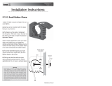
1. Assemble middle section with side brackets
as shown in picture. Leave screws finger-tight. Be
sure to use four holes to bolt side brackets to
middle section.
2. Clamp hitch receiver with 3/8" thick spacer
between the receiver and the frame at the rear. Align
ends of brackets with end of frame as shown. Align
holes in 3/8" spacers with slots
in brackets.
3. Using holes in brackets as a guide, drill 1/2"
diameter holes into frame at locations shown.
4. Insert 1/2" screws with 1/4" plates through frame
and into brackets. Install flat washers and lock nuts
on 1/2" screws.
5. Tighten nuts in the following order: First torque
the 3/8" nuts to 40 ft-lb. Then torque 1/2" nuts to 70
ft-lb.
6. Install plastic plugs into 3/8" holes in middle sec-
tion.
1801005 Hitch Receiver, Class 4
1973-1996 Ford Full Size Pickup
1997 – F-250/F-350 Super-Duty
1 3004980 1 Middle Section
2 3004908 1 Side Bracket
3 3004909 1 Side Bracket
4 FCS038016125 8 Screw, HHC-3/8-16 x 1.25 Gr 5 Zn
5 FWF038081006 16 Washer, Flat 3/8 SAE Zn
6 FNE038016044 8 Nut, Nylock 3/8-16 x 7/16 Zn
7 3004906 2 3/8" Spacer
8 3004907 4 Bolt Plate, 1/4"
9 3001384 4 Screw, Hex Cap 1/2-13 x 2" Gr 5 Zn
10 FWF050106010 4 Washer, Flat 1/2" SAE Zn
11 FNE050013053 4 Nut, Nylock 1/2-13 Zn
12 3005078 2 Plug, 7/16" Dia. Poly
ITEM PART NO. QTY. DESCRIPTION
Bill of Materials
—continued
4

www.buyersproducts.com
Phone (440) 974-8888
Fax 800-841-8003
Quality since 1946
Tools Required:
• 3/4" Socket
• 3/4" Wrench
• 9/16" Socket
• 9/16" Wrench
• Torque Wrench
• 1/2" Drill Bit
1. Align side brackets with rear edge of frame.
Attach brackets to frame as shown with 1/2" screws
and 1/4" plates down through rear holes in frame.
Install flat washers and lock nuts on these screws.
Leave nuts loose at this time.
2. Install middle section as shown with side brack-
ets on the outside of it. Bolt through holes shown
using 3/8" screws, washers and lock nuts. Be sure
to use four holes to bolt side brackets to middle
section. Tighten enough for brackets to make full
contact with middle section.
3. With 1/2" drill, drill two front holes. Install 1/2"
screws, 1/4" plates, washers and lock nuts. Leave
nuts loose at this time.
4. Tighten nuts in the following order: First torque
3/8" nuts to 40 ft-lb. Then torque 1/2" nuts to 70
ft-lb.
5. Install plastic plugs into 3/8" holes in
middle section.
1 3004980 1 Middle Section
2 3004908 1 Side Bracket
3 3004909 1 Side Bracket
4 FCS038016125 8 Screw, HHC-3/8-16 x 1.25 Gr 5 Zn
5 FWF038081006 16 Washer, Flat 3/8 SAE Zn
6 FNE038016044 8 Nut, Nylock 3/8-16 x 7/16 Zn
7 3004907 4 Bolt Plate, 1/4"
8 3001384 4 Screw, Hex Cap 1/2-13 x 2" Gr 5 Zn
9 FWF050106010 4 Washer, Flat 1/2" SAE Zn
10 FNE050013053 4 Nut, Nylock 1/2-13 Zn
11 3005078 2 Plug, 7/16" dia. Poly
ITEM PART NO. QTY. DESCRIPTION
Bill of Materials
1801005 Hitch Receiver, Class 4
1997-2006 – F-250/F-350 Super-Duty
—continued
5

www.buyersproducts.com
Phone (440) 974-8888
Fax 800-841-8003
Quality since 1946
Tools Required:
• 3/4" Socket
• 3/4" Wrench
• 9/16" Socket
• 9/16" Wrench
• Torque Wrench
1. Align side brackets with rear edge of frame. Place
3/8" thick spacers between brackets and frame as
shown. Attach brackets to frame as shown with 1/2"
screws and 1/4" plates down through frame, spacers
and brackets. Use first and last holes in the brackets.
Install flat washers and lock nuts on screws. Leave
nuts loose at
this time.
2. Install middle section with side brackets on the
inside of it. Attach middle section using 3/8" screws,
washers and lock nuts. Be sure
to use four holes to
1801005 Hitch Receiver, Class 4
1997-2003 Ford F-150 & Light-Duty F-250
2004 – Ford F-150 Old Style Only
bolt side brackets to middle section.
3. Tighten nuts in the following order: First torque
3/8" nuts to 40 ft-lb. Then torque 1/2" nuts to 70
ft-lb.
4. Install plastic plugs into 3/8" holes in middle sec-
tion.
1 3004980 1 Middle Section
2 3004909 1 Side Bracket
3 3004908 1 Side Bracket
4 FCS038016125 8 Screw, HHC-3/8-16 x 1.25 Gr 5 Zn
5 FWF038081006 16 Washer, Flat 3/8 SAE Zn
6 FNE038016044 8 Nut, Nylock 3/8-16 x 7/16 Zn
7 3004907 4 Bolt Plate, 1/4"
8 3001384 4 Screw, Hex Cap 1/2-13 x 2" Gr 5 Zn
9 FWF050106010 4 Washer, Flat 1/2" SAE Zn
10 FNE050013053 4 Nut, Nylock 1/2-13 Zn
11 3004906 8 Spacer, 3/8"
12 3005078 2 Plug, 7/16" dia. Poly
ITEM PART NO. QTY. DESCRIPTION
Bill of Materials
—continued
2

www.buyersproducts.com
Phone (440) 974-8888
Fax 800-841-8003
Quality since 1946
3. Using forward most holes in brackets as a guide,
drill 1/2" holes and install 1/2" screws with 1/4"
plates through frame and brackets. Then install 1/2"
washers and lock nuts.
4. Tighten nuts in the following order: First torque
3/8" nuts to 40 ft-lb. Then torque 1/2" nuts to 70
ft-lb.
5. Install plastic plugs into 3/8" holes in
middle section.
1 3004980 1 Middle Section
2 3004908 1 Side Bracket
3 3004909 1 Side Bracket
4 FCS038016125 8 Screw, HHC-3/8-16 x 1.25 Gr 5 Zn
5 FWF038081006 16 Washer, Flat 3/8 SAE Zn
6 FNE038016044 8 Nut, Nylock 3/8-16 x 7/16 Zn
7 3004907 4 Bolt Plate, 1/4"
8 3001384 4 Screw, Hex Cap 1/2-13 x 2" Gr 5 Zn
9 FWF050106010 4 Washer, Flat 1/2" SAE Zn
10 FNE050013053 4 Nut, Nylock 1/2-13 Zn
11 3005078 2 Plug, 7/16" dia. Poly
ITEM PART NO. QTY. DESCRIPTION
Bill of Materials
Tools Required:
• 3/4" Socket
• 3/4" Wrench
• 15/16" Socket
• 15/16" Wrench
• Torque Wrench
• 1/2" Drill Bit
• 21 mm Wrench
1. Use existing holes at rear of frame and install 1/2"
screws through 1/4" plates and into frame. With 1/2"
screws, washers and lock nuts attach brackets to
frame. Do not install fasteners in the forward holes in
brackets at this time.
2. Install middle section as shown. Use bolting loca-
tions indicated. Attach middle section using 3/8"
screws, washers and lock nuts. Be sure to use four
holes to bolt side brackets to middle section.
1801005 Hitch Receiver, Class 4
2000-2006, Toyota Tundra
—continued
3

www.buyersproducts.com
Phone (440) 974-8888
Fax 800-841-8003
Quality since 1946
3005083 Rev. E
Warranty
Buyers Products Co. warrants all truck/trailer hardware manufac-
tured or distributed by it, to be free from defects in material and
workmanship for a period of one year from date of shipment. Parts
must be properly installed and used under normal conditions.
Any product which has been altered, including modification, mis-
use, accident or lack of maintenance will not be considered under
warranty. Normal wear is excluded. The sole responsibility of Buyers
Products Co. under this warranty is limited to repairing or replacing any
part or parts which are returned, prepaid, and are found to be defective
by Buyers Products Co. Authorization from Buyers Products Co. must
be obtained before returning any part. No charges for transportation
or labor performed on Buyers’ products will be allowed under this
warranty.
12
/