Page is loading ...

www.buyersproducts.com
Phone (440) 974-8888
Fax 800-841-8003
1
Installation Instructions
Topsider Toolbox
DANGER
Do not use this toolbox for storing or transporting flammables,
explosives, hazardous waste, gasoline, solvents, propane
tanks, acetylene tanks or cutting torches. This product is only
intended and safe for storing and transporting small tools and
equipment. Any modifications or unintended use of this toolbox
could create a hazardous condition that could result in death or
serious personal injury or property damage.
To prevent rust touch up any drilled holes with aerosol
paint. To prevent leaks, seal drilled holes with a silicone
sealant around the fasteners.
1. Park the vehicle on a level surface.
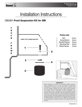
2. Turn the toolbox over and at each end of the box mark a line
about 6" long, about 1" inside of and parallel to the end of the
box. Mark 2 more lines centered in the box 12" apart. See figure
1.
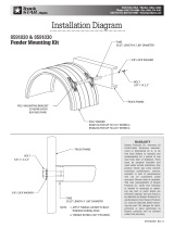
3. Place the mounting pad in position on the top of the truck
fender as shown in Figure 2. You may want to tape the pad to
the fender to keep it from moving during installation.
4. Place the toolbox in position on top of the truck bed and
support the rear of the box so the box can sit safely by itself.
Support the box with scrap lumber or similar material. Level the
box so it is horizontal when viewed from the rear.
Fasten the support legs directly to the truck floor and not
to any bed liner or floor mat.
CAUTION
To keep foreign materials out of your eyes when working,
drilling or checking the underside of the vehicle, always wear
protective eyewear.
Before you begin installing:
1. Read and understand these instructions
completely.
2. Verify that you have received all the parts
listed in the bill of materials.
Tools Required:
• (2) 1/2" Open or Boxed End Wrench
• Ratchet Wrench with 1/2" Deep Well Socket
• Electric Drill
• 1/2" and 3/8" Drill Bits
• Carpenters Square
• Utility Knife or Scissors
• Tape
• 9/16" Open or Boxed End Wrench
—continued

www.buyersproducts.com
Phone (440) 974-8888
Fax 800-841-8003
2
3004541_C
WARRANTY
Buyers Products Co. warrants all truck/trailer hardware manufac-
tured or distributed by it, to be free from defects in material and
workmanship for a period of one year from date of shipment. Parts
must be properly installed and used under normal conditions.
Any product which has been altered, including modification, mis-
use, accident or lack of maintenance will not be considered under
warranty. Normal wear is excluded. The sole responsibility of Buyers
Products Co. under this warranty is limited to repairing or replacing any
part or parts which are returned, prepaid, and are found to be defective
by Buyers Products Co. Authorization from Buyers Products Co. must
be obtained before returning any part. No charges for transportation
or labor performed on Buyers’ products will be allowed under this
warranty.
WARNING
Check under vehicle for locations of fuel tanks, fuel lines, brake
lines, electrical wiring, etc. before drilling any holes. Floor bolts
near a gas tank should be installed from the bottom of the truck
to guard against puncturing the tank in the event of collision.
5. Place one support leg as close to the rear corner of the box
as possible and use a square to get proper vertical alignment.
The closer the legs are mounted to the rear of the box, the more
stable the box will be.
The foot of each of the support legs must be squarely
mounted on or between the floor ribs.
6. Mark both leg foot holes on the floor of the truck bed and
both leg top holes on the end of the toolbox.
7. Repeat the leg placement and marking process at the other
end of the toolbox.
8. Using the bed lip as a guide, scribe a mark across the lines
drawn in Step 2 on the underside of the box and at the point
where the box and bed lip meet. If there is a stake pocket in the
truck bed below the point where any of the 6" long lines inter-
sect the truck bed, draw a new line just outside the stake pocket
area and complete step 8 for that location.
9. Remove the toolbox from the truck, turn it over and mark the
bottom 1/2" toward the inside of the toolbox at the 4 scribed
lines created in Step 8. This is where the holes should be drilled.
10. Drill the necessary 3/8" diameter holes into the sides and
bottom of the toolbox as well as the truck bed floor.
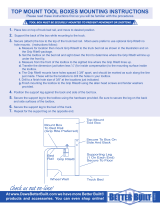
11. Fasten the legs to the toolbox and install the box into the
truck bed. Fasten the leg feet to the floor and install the "J" bolts
as shown in Figure 3.
Fig. 1
Fig. 2
Fig. 3
/