Page is loading ...

1
Average Material Weights
Materials to use Weight (pounds per cubic yard)
Fine Salt-Dry 2,250
Coarse Salt-Dry 1,431
Sand/Salt up to 50/50 Mix-Dry 2,700
Note: To calculate the total spreader weight (including ice
control material), add the empty spreader weight plus the ice
control material and spreader accessories.
Installation Instructions
—continued inside
SHPE1500, SHPE1500RED, SHPE1500YEL
Series SaltDogg
®
Electric Drive Poly Hopper
Spreader 1.5 cubic yards
Serial Number 9700 and higher.
Protected by U.S. patent D520 524; 9,562,333
Table of Contents
General Information .................................................................... 1
Warranty Information .................................................................. 1
Safety Precautions ..................................................................... 2
Installation Instructions ............................................................2-3
Spreader Operation .................................................................... 4
Spreader Maintenance ............................................................... 5
Repair Parts & Drawings .........................................................6-8
General Information
Spreader model numbers:
• SHPE1500 - spreader with standard chute
• SHPE1500X - spreader with extended chute
Overall Length: 92-1/8"
Overall Width: 50-1/2"
Overall Height (installed): 37-1/2"
Empty Weight: 410 lbs.
Capacity Struck: 1.5 cu. yd.
Average Installation Time: 3 hrs.
Vehicle Requirements
• 3/4 or 1 ton Pickup Truck above 8,500 lbs. GVWR.
• 135 amp or higher alternator is recommended.
Materials Recommended to Spread
CAUTION
Do not overload vehicle beyond the vehicle’s GVWR or
GAWR. Check vehicle's load rating certification sticker for
maximum vehicle capacity.
9049 Tyler Blvd. • Mentor, Ohio 44060
Phone (440) 974-8888 • Fax (800) 841-8003
www.saltdogg.com
SHPE1500 SALTDOGG SPREADER WARRANTY
INFORMATION
This warranty replaces all previous warranties and no
employee of this company is authorized to extend addi-
tional warranties, or agreements, or implications not
explicitly covered herein.
Buyers Products Company warrants all parts of the
product to be free from defects in material and workman-
ship for a period of two (2) years. Parts must be properly
installed and used under normal conditions. Normal wear
is excluded.
Any part, which has been altered, including modifica-
tions, misuse, accident, or lack of maintenance will not
be considered under this warranty.
The sole responsibility of Buyers Products Company
under this warranty is limited to repairing or replacing any
part(s), which are returned, prepaid, 30
days after such defect is discovered, and returned part(s)
are found to be defective by Buyers Products Company.
Authorization from Buyers Products Company must be
obtained before returning any part. The following infor-
mation must accompany defective parts returned
to Buyers Products Company: RMA #, spreader model,
serial number, date installed, and distributor from whom
purchased.
Buyers Products Company shall not be liable for damage
arising out of failure of any unit to operate properly, or
failure, or delay in work, or for any consequential dam-
ages. No charges for transportation or labor performed
on any part will be allowed under this warranty.

2
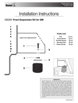
13.5"
2" x 4"
2" x 6"
FIT TO BOX
FIT TO BOX
8"
Safety Precautions
Fig. 2
Fig. 3
Fig. 4
1. Read the entire Installation Instructions before operating this
spreader.
2. Read all safety decals on the spreader before operating.
3. Check to make sure all safety guards are securely mounted
into place before operating this spreader.
4. Verify that all personnel are clear of the spreader spray area
before starting or operating this spreader.
5. Do not over-load your vehicle beyond payload limits. If there
are any questions, contact the vehicle manufacturer.
6. Do not adjust, clean, lubricate or unclog material jambs
without first turning off the spreader.
7. Do not climb on or in the spreader during operation.
8. Do not ride on the spreader while the vehicle is
in motion.
9. Make sure the spreader is securely fastened to the vehicle in
accordance with this manual.
10. Do not operate a spreader that is in need of maintenance or
repairs.
11. Always disconnect the battery before removing or replacing
electrical components.
Installation Instructions
1. Mounting the Spreader onto the Vehicle:
A. Remove the tailgate from the vehicle.
B. Check truck’s bed for any sharp debris or foreign objects.
These can cut and seriously damage poly hopper.
C. Lift spreader using tie downs. See Figure 1.
D. Slide spreader forward until the steps on rear legs of the
spreader make contact with truck’s bed. Measure the distance
from the front of the truck bed to front of the hopper's front
legs. Fabricate spacer to fit between front of the spreader and
front of the bed as shown in Figures 2 & 3.
E. Center the spreader from side to side on the vehicle.
Securely strap the spreader to the truck using four ratchet
straps as shown in Figure 4.
Verify with the vehicle’s manufacturer that the factory
installed anchor points are designed for tie-down such load.
Inspect straps and hardware after each time spreader is
loaded. Tighten straps and hardware if necessary.
WARNING
Observe the following Safety Precautions before, during and
after operating this spreader. By following these precautions and
common sense, possible injury to persons and potential damage
to this machine may be avoided.
Use Tie Downs
Fig. 1

3
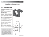
LOCK CHUTE
USING BOTH LATCHES
WARNING
Use extreme caution when working around an operating
vehicle engine.
WARNING
DO NOT MOUNT CONTROLLER IN WAY OF AIR BAG DEPLOYMENT
Fig. 5
Fig. 6
ATTENTION
Do not connect black (negative) wire to any part of vehicles
frame. Connect this terminal to battery's negative terminal.
2. Mounting the Spinner/Chute Assembly
A. Attach the Chute Assembly to the spreader. First, hook the
Chute to the spreader by openings in the Chute’s handle (Fig.
5).
3. Install Control Box & Vehicle Wiring Harness (Fig.7).
NOTE: THIS IS A WIRE GROUND ELECTRICAL SYSTEM! NO
CONNECTIONS TO TRUCK'S FRAME OR BODY ALLOWED!
ALWAYS DISCONNECT BATTERY BEFORE ATTEMPTING
TO INSTALL ELECTRICAL COMPONENTS ON YOUR
VEHICLE.
B. Rotate the chute into operating position and lock using the
two spring latches (Fig. 6).
WARNING
Do not drill holes into fuel tanks, fuel lines, through electrical
wiring, etc that may be damaged by drilling.
To insure good performance of your spreader, check the
condition of truck’s electrical system. Using digital voltmeter,
check alternator and battery voltage. The voltage reading should
fall between 13.6 and 15.3 volts with engine running, head lights
and heater fan turned on. If voltage reading falls out of this range,
check and adjust your electric system.
A.
Lay out a wiring path for the Vehicle Wiring Harness. Connect
the Wire Harness smaller terminal to the Chute’s harness, large
terminal to the Hopper’s harness. Drill all necessary holes or use
existing ones to pass the round connector into the trucks cab.
Secure harness to truck’s frame.
B. Mount the Controller in a convenient location in the truck cab.
Do not mount controller directly in front of the heat vents. Allow
ample air space around controller. Protect controller from water,
dirt and dust.
C. Apply dielectric grease or similar compound to
connectors before assembly. Connect the round
connector on the wire harness to the round connector on the
controller.
D. Lay out path for the power cable in the truck’s engine
compartment. Drill hole in the firewall or use an existing one to
pass the wire harness. Passing the power cable from inside of
the cab to the battery is recommended to protect the large high
amperage connector. Do not route the power cable close to
exhaust system!
E. Connect power cable connector to controller.
F. Connect the power cable ring terminals to the truck battery
(fig. 7).

4
Thoroughly clean battery terminals. Make sure battery
terminals have no tarnish or corrosion.
DO NOT CONNECT WIRE HARNESS TO DAMAGED
OR CORRODED TERMINALS! IT MAY RESULT IN
OVERHEATING, LOST POWER AND POTENTIAL
CONTROLLER DAMAGE!
G. Attach utility light (optional) to spreader hopper in desired
location. Connect as shown in Fig. 7. Use utility light kit part
number 3018009.
H. See controller instructions for latest updates and error
codes.
Spreader Operation
1. Different materials absorb moisture at different rates and
some materials may not perform as desired. Substitution
of an alternative material may be necessary for optimum
performance.
2.
When filling hopper use the supplied screen to prevent large
chunks of material and debris in the material to get into hopper
and cause damage.
3.
Material must never be left in hopper for an extended
period of time. Material will absorb moisture, bind, harden
and could prevent spreader from proper operation or may
damage the spreader.
4.
The SHPE1500 spreader is equipped with a dual independent
speed controller with warning indicators and a vibrator switch.
To start the spreader, press the ON-OFF switch. Switch will
illuminate. The auger will accelerate to full speed for 2 seconds,
then slow down to dialed speed. The spinner will accelerate to full
speed for 2 seconds, then slow down to dialed speed.
5.
To activate the vibrator press the vibrator switch ON. Vibrator
switch will illuminate.
6.
To stop the spreader, push ON-OFF switch to OFF position.
Material Flow Adjustments
Always use screen during spreader operation!
Various materials have different moisture absorption rate,
some materials may not perform as desired. Therefore, the
substitution of the alternate material may be necessary for
optimum performance.
SHPE1500 has two discharge openings in the bottom of the
hopper. Material flow through these openings can be controlled
using two sliding baffles. The spreader is shipped from the
factory with baffles adjusted for dry salt. In this setting rear
baffle has 4.0" opening and baffle in the middle of the hopper
has 2.0" opening. However if you are using a sand/salt mixture
or any chunky and hard to flow materials, adjust the rear baffle
opening to 3" and the baffle in the middle of the hopper to a 1"
opening.
IMPORTANT! -Always open rear (closer to gear motor
compartment) opening first. Always turn off power before
adjusting baffles!
Fig. 7
3014199
3006724
3035933
CB120PB
3001379
BATTERY POSITIVE
BATTERY NEGATIVE

5
Spread Pattern Adjustment
Spread pattern can be adjusted by changing spinner disc speed
on controller by turning Spinner knob to desired speed level
from 1 (low) to 9 (high). Direction of material spread can also be
adjusted by rotating shield on chute assembly. To rotate shield
lose 2 wing nuts, rotate shield in desired direction, and retighten
wing nuts. See Fig. 8. Make sure that after adjustment, bracket
stays inside shield groove located on top of shield. In addition,
chute assembly can be adjusted to lighter (drier) and heavier
(more moist) materials. Use different holes on bracket for lighter
or heavier materials to have material drop on spinner disc
center. See Fig. 8.
LOOSE WING NUTS
ROTATE SHIELD
BRACKET
POSITION
ADJUSTMENT
Fig. 8
Controller Warnings
Check controller instruction sheet for latest controller updates
and troubleshooting codes. Controller instruction sheet is inside
controller shipping box.
IMPORTANT! INSTALLER, DO NOT DISCARD CONTROLLER
INSTRUCTION SHEET. STAPLE SHEET TO SPREADER
MANUAL AND GIVE TO END USER!
Note: To unclog auger manually, first remove the chute. Apply
1-1/4" open wrench on auger’s nut. Turn auger counterclockwise
several times.
Note: Do not run the vibrator longer than 30 minutes with 15
minutes between runs to avoid overheating.
Spreader Maintenance
1. Wash spreader after every use. Make sure no material is left
under auger and/or inside trough.
2. Inspect and retighten fasteners after every 5-7 hours of
operation.
3. Lubricate bearing every 7-10 hours of operation using general
automotive grease.
4. Inspect terminals/connectors every time you disconnect
spreader from wire harness. Apply thin layer of dielectric grease
on terminals. If any tarnish/corrosion is found, clean terminals
and apply dielectric grease.
5. Use dielectric grease on all electrical connectors before an
electrical connection is made or after connector is disconnected
6. Grease and spray with lubricant Auger bearing after every 20
hours of use.
7. Empty the spreader of all ice control materials when not in
use. Wash out the spreader to prevent material builds up.
8. It is recommended to cover spreader with the tarp during
storage periods. Tarp can be attached to anchors on both sides
of tie downs.
WARNING
Never remove spreader with material in hopper.
End of Season Maintenance
1.
Wash spreader. Make sure no material or residue is left in and
outside the hopper.
2.
Lubricate bearing using general automotive grease.
3.
Inspect wire harness, connectors for broken insulation, missing
components. Replace if necessary.
4.
Apply dielectric grease on all electrical connectors.
5.
Store hopper indoors, in a dry, cool place.
6.
Remove controller from truck. Store controller indoors, in a dry,
cool place.
7.
Inspect wire near connectors. Check for broken or missing
insulation. Check for tarnished or corroded wires. Trim corroded
wires and replace connectors if necessary.
Summer Storage
1.
Apply dielectric grease or similar protective compound on all
electrical connectors & protect them with caps before storage.
2. Disconnect and remove speed controller from vehicle and
store it in dry and cool place. Protect controller from excessive
heat and moisture.
3. Clean hopper and trough from all kinds of debris.
4. Remove, thoroughly lubricate and reinstall trough bearing.
5. Protect hopper from excessive temperatures during
summer storage.

6
Bill of Materials
ITEM PART NO. QTY. DESCRIPTION
1 3007526 1 CHUTE POLY. EXT. LENGTH
2 3006833 1 GEAR MOTOR 12 VDC. SPINNER
3 3007824 1 RETAINER GEARMOTOR, CHUTE
4 FWL031058008SS 3 WASHER, 5/16 LOCK SST
5
FCS031018063SS
3 SCREW, HHC 5/16-18 X 5/8 SST
6 3012393 1 SPINNER, 14" POLY CW
7 3027699 1 HANDLE, CHUTE
8 3007564 1 BRACKET, SHIELD SST
9 3007004 1 SHIELD, SPINNER, SHPE1500
10 3007413 1 COVER, GEAR MOTOR, CHUTE
11 FWF038100007SS 16 WASHER, FLAT 3/8 USS SST
12 FCS038016100SS 10 SCREW, HHC 3/8-16 X 1 304 SST
13 FNE038016044SS 10 NUT, NYLOCK 3/8-16 X 7/16 SST
14 3007522 6
SCREW, SHEET MTL #12x1.0 HEX WASHER
HD SST
15 3007113 1 PIN, CLEVIS, 5/16 X 2-1/2, .141 HOLE ZN
16 FPC013000100 1 COTTER PIN, 1/8 X 1, ZINC
17 3002631 1 LABEL, "NO STEP"
18 3007844 1 DECAL, DANGER STAY CLEAR
19 3025065 1 BUSHING STRAIN RELIEF
Repair Parts - Standard Chute Assembly Repair Parts - Extended Chute Assembly
1
2
3
4
5
6
7
8
9
10
11
12
13
14
15
16
17
18
19
20
1
2
3
4
5
6
7
8
9
10
11
12
13
14
15
16
17
18
19
Bill of Materials
ITEM PART NO. QTY. DESCRIPTION
1 3025063 1 CHUTE POLY, SHPE STD. LENGTH
2 3033665 1 BRACKET WELDMENT, CHUTE
3 3006833 1 GEAR MOTOR 12 VDC. SPINNER
4
3027699
1 HANDLE, CHUTE
5 FWF038100007SS 10 WASHER, FLAT 3/8 USS SST
6 FCS038016125SS 8 SCREW, HHC-3/8-16 X 1.25 SST
7 FNE038016044SS 8 NUT, NYLOCK 3/8-16 X 7/16 SST
8 FWF031075006SS 3 WASHER, 5/16 SAE SST
9 FCS031018063SS 3 SCREW, HHC 5/16-18 X 5/8 SST
10 3012393 1 SPINNER, 14" POLY CW
11 3025067 1 ENCLOSURE, GEAR MOTOR
12 3025065 1 BUSHING STRAIN RELIEF
13 3001537 3 SCREW, S0CBHCS #10 X 5/8 SST
14 FNE010024024SS 3 NUT, ELASTIC STOP 10-24 SS
15 3007113 1 PIN, CLEVIS, 5/16 X 2-1/2, .141 HOLE ZN
16 3017444 1 SHIELD, CHUTE
17 3014960 2 BOLT, 3/8-16 X 1 CARRIAGE SHORT NECK SS
18 3017356 2 WASHER, EXTERNAL TOOTH LOCK 3/8 SS
19 3025064 2
NUT, 3/8-16 WING, SST
20 3014994 1
PIN,COTTER,1/8IN X 1IN SST

7
Repair Parts-Hopper Assembly
Bill of Materials
ITEM PART NO. QTY. DESCRIPTION
1
3005574 1 HOPPER POLY 1.5 CU. YA., BLACK
3025162 1 HOPPER POLY 1.5 CU. YA., RED
3025164 1 HOPPER POLY 1.5 CU. YA., YELLOW
2 3006959 2 BAFFLE, SHPE1500
3 3007115 14 WASHER, FLAT 3/8 X 1.5 X.048 SST
4 FWL038069009SS 14 WASHER, LOCK RHS-3/8 SST
5 FCS038016075SS 14 SCREW, HHC-3/8-16 X 3/4 SST
6 3011865 1 TROUGH ASSEMBLY, SHPE
7 3006958 4 TIE DOWN
8 3006974 4 STUD, 1/2-13x.75 BOTH ENDS, 9.75" LG, ZC
9 3009802 8 ANCHOR, TARP, POLY SHPE
10 FNE050013053 8 NUT, NYLOCK 1/2-13 ZINC
ITEM PART NO. QTY. DESCRIPTION
11 9240132 1 DECAL #2, DANGER BEFORE SVCE
12 3007731 1 BRACKET VIBRATOR, LONG SST
13 FNE038016044SS 2 NUT, NYLOCK 3/8-16 X 7/16 SST
14 4375 4 CLAMP, HOSE .4375, 9/32 HOLE
15 3007522 6
SCREW, SHEET MTL #12x1.0 HEX WASHER HD
SST
16 3007236 1 COVER GEARMOTOR
17 FWL025050006SS 6 WASHER, 1/4 IN. SPRING LOCK SST
18 FCS025020075SS 6 SCREW, CAP 1/4-20 X 3/4 SST
19 3007821 1 STRAIN RELIEF BUSHING
20 3012898 1 DECAL, CHECK STRAPS
21 3022955_ 1 HOSEGREASE, 1/8 NPT, 36 IN LONG
22 3020713 1 CONNECTOR, MALE, FEMALE
23 H3309X2 1 CONNECTOR, FEM NPT TO FEM NPT 1/8 X 1/8
24 800 1 GREASE FITTING, 1/4 STD
1 2
3
4 5
6 7
8
9
10
11
12
13
14
15
16
17
18
19
20
21 22 23 24

8
3028127_D
Repair Parts-Spreader
9049 Tyler Blvd. • Mentor, Ohio 44060
Phone (440) 974-8888 • Fax (800) 841-8003
www.saltdogg.com
Repair Parts-Trough Assembly
1
2
3
4
5
6
7
8
9
10
11
12
13
14
Bill of Materials
ITEM PART NO. QT Y. DESCRIPTION
1 3007357 1 TROUGH WELDMENT SHPE1500
2 3007000 1 GASKET, FELT BEARING
3 3018919 1 BEARING, 2-HOLE FLANGED 1" SST
4 FNE038016044SS 4 NUT, NYLOCK 3/8-16 X 7/16 SST
5
3018007
1 AUGER SHPE SST
6 3007730 1 BRACKET, VIBRATOR SHORT
7 3007416 1 VIBRATOR 200 LBS 12 VDC
8 3007824 1 RETAINER GEARMOTOR, CHUTE
9 3009995 1 GEAR MOTOR, AUGER SHPE
10 FWL031058008SS 3 WASHER, 5/16 LOCK SST
11 FCS031018063SS 3 SCREW, HHC 5/16-18 X 5/8 SST
12 FPY031000150 1 PIN, CLEVIS, 5/16 X 1-1/2, W/ 5/32 PH, ZN
13 3014994 1 PIN,COTTER,1/8IN X 1IN SST
14 3006844 1 WIRE HARNESS
Bill of Materials
ITEM PART NO. QTY. DESCRIPTION
1
3006837 1 HOPPER POLY 1.5 CU YD ASSEMBLY
3025163 1 HOPPER POLY 1.5 CU YD ASSEMBLY, RED
3025165 1 HOPPER POLY 1.5 CU YD ASSEMBLY, YELLOW
2 3025070 1 CHUTE ASSEMBLY. STD LENGTH
3 3007039 1 SCREEN, WELDMENT SHPE1500
4 3007115 4 WASHER, FLAT 3/8 X 1.5 X.048 SST
5 FWL038069009SS 4 WASHER, LOCK RHS-3/8 SST
6 3006760 4 SCREW, HHC-3/8-16 X 1/2 SST
7 3008987 1 PLATE, SERIAL NO. SHPE1500 SERIES
8 3007522 2 SCREW, SHEET MTL #12x1.0 HEX WASHER HI
9 3007527 1 CHUTE POLY EXT. ASSEMBLY
10 3028126 1 HARDWARE KIT SHPE1500
11 3014199 1 CONTROLLER, SHPE, SALT DOGG
12 3006724 1 WIRE HARNESS, MAIN
13 3035933 1 POWER CABLE, CONTROL BOX
14 1496505 1 HOLD DOWN KIT, SPREADER (4 STRAPS)
15 3006964 1 TARP, SHPE1500
16 TS9 8 STRAP, RUBBER TARP 9"
17 9225 16 S-HOOK, 2.5" ZN, TARP STRAP
3001379 1 BATTERY CABLE
CB120PB 1 CIRCUIT BREAKER
Service Parts and Accessories
PART NO. DESCRIPTION
3012431 Replacement Motor for 3006833, 3027293
3021617 Replacement Coupler for 3006833, 3027293
3019085 Replacement Motor for 3009995
3021616 Rocker Switch for Controller 3014199
3020624 Remote Grease Kit
LS6 Wetting System, 30 Gal.
LS6H Wetting System, Hydraulic, 30 Gal.
1
2
3
4
5
6
7
8
9
10
11
12
13
14
15
16
17
18
/