Page is loading ...

MI810
Intel
®
Atom
®
945GSE
Mini-ITX Motherboard
USER’S MANUAL
Version 1.1

ii
MI810 User’s Manual
Acknowledgments
Award is a registered trademark of Award Software International,
Inc.
PS/2 is a trademark of International Business Machines
Corporation.
Intel and Atom are registered trademarks of Intel Corporation.
Microsoft Windows is a registered trademark of Microsoft
Corporation.
Winbond is a registered trademark of Winbond Electronics
Corporation.
All other product names or trademarks are properties of their
respective owners.

MI810 User’s Manual iii
Table of Contents
Introduction ....................................................... 1
Product Description ............................................................. 1
Checklist .............................................................................. 2
MI810 Specifications .......................................................... 3
Board Dimensions ............................................................... 4
Installations ....................................................... 6
Installing the Memory ......................................................... 7
Setting the Jumpers ............................................................. 8
Connectors on MI810 ........................................................ 12
BIOS Setup ....................................................... 23
Drivers Installation ...................................... 47
Intel Chipset Software Installation Utility......................... 48
VGA Drivers Installation .................................................. 50
Realtek High Definition Audio Driver Installation ........... 52
LAN Drivers Installation ................................................... 53
Appendix ........................................................... 55
A. I/O Port Address Map ................................................... 55
B. Interrupt Request Lines (IRQ) ...................................... 56
C. Watchdog Timer Configuration .................................... 57

iv
MI810 User’s Manual
This page is intentionally left blank.

INTRODUCTION
MI810 User’s Manual 1
Introduction
Product Description
The MI810 Mini ITX board incorporates the Intel® 945GSE Express Chipset
with ICH7M, configured with the Intel Atom processor N270 at 1.6GHz,
FSB533 and the Mobile Intel 945GSE Express Chipset with the ICH7M.
The MI810 Mini ITX board features the Intel's Graphics Media Accelerator 950
core, making it compatible with Windows Vista Premium, and Chrontel CH7307
DVI accelerator to support display interfaces including VGA CRT, dual channel
LVDS and a DVI port.
The new Intel® Graphics Media Accelerator 950 (Intel® GMA 950) graphics
core is an intelligent and responsive graphics engine built into the chipset that is
on the motherboard. This integration provides incredible visual quality, faster
graphics performance and flexible display options without the need for a
separate graphics card.
The main features of the MI810 Mini ITX Motherboard are:
Supports Intel Atom 270 processor with 1.6GHz speed
Two DDRII SDRAM DIMM supports up to 2GB of DDR2
400/533MHz memory
Onboard 10/100 BaseT and Intel 82574L PCI-Express Gigabit LAN
Intel® 945GSE VGA for CRT, LVDS, DVI
2x SATA, 8x USB 2.0, 4x COM, Watchdog timer
1x PCI, 1x MiniPCIe, CF socket, DC-in for +12V/+19V input
Dimensions of the board are 170mm x 170mm.
Ordering Information:
MI810F: Intel Atom, 1.6GHz, 945GSE chipset with DVI, LVDS, 1x 10/100
LAN, 1x Gigabit LAN, Mini PCI-E, PCI
MI810: Intel Atom, 1.6GHz, 945GSE chipset with DVI, LVDS, 1x 10/100
LAN, Mini PCI-E, PCI

INTRODUCTION
2
MI810 User’s Manual
Checklist
Your MI810 package should include the items listed below.
• The MI810 Intel
®
Atom Mini-ITX motherboard
• This User’s Manual
• 1 CD containing chipset drivers and flash memory utility
• Cable kit (IDE, 2x Serial port, Serial ATA)

INTRODUCTION
MI810 User’s Manual 3
MI810 Specifications
CPU Type Intel New architecture CPU on 45nm processor,
Intel® Atom™ processor N270, 1.60GHz
L2 Cache=512K
FSB 533MHz
Green /APM APM1.2
BIOS Award BIOS, support ACPI Function
Chipset INTEL 945GSE Chipset
GMCH: 82945GSE 27 mm x 27 mm -998-pin FCBGA
ICH7M: 82801GBM 31mm x 31mm -652-pin BGA
Memory DDRII 533 DIMM x 2
(w/o ECC function), supports single channel. Max. 2GB
VGA 945GSE built-in, Intel® Graphics Media Accelerator 950
Graphics Core, Supports CRT & 18 bits dual channels LVDS
interface w/ DF13 socket x2
DVI onboard Chrontel CH7307C for DVI with connector on edge
LAN 1. ICH7M built-in 10/100BT MAC + Intel 82562ET PHY
2. Intel 82574L PCI Express Gigabit LAN controller x1
USB (Universal Serial
Bus)
ICH7M built-in USB 2.0 host controller, support 8 ports
Serial ATA Ports ICH7M built-in SATA controller, supports 2 ports
Parallel IDE ICH7M built-in one channel Ultra DMA 33/66/100, CF
Audio ICH7M Built-in Audio controller ALC 662 5.1-Channel (Line-in,
Line-out & MIC)
LPC I/O Winbond W83627EHG: COM1(RS232), COM2
(RS232/422/485), Hardware monitor (3 thermal inputs, 4
voltage monitor inputs, VID0-4 & 2 Fan Headers), LPT
2nd LPC I/O Fintek F81216DG COM3 &COM4(RS232)
Digital IO 4 in & 4 out
Keyboard/Mouse
Connector
Supports PS/2 Keyboard/Mouse
Expansion Slots PCI slot x1, PCI-E (x1) slot x1 and Mini PCI-E (x1) socket x1
Power Connector DC Power jack x1 for +12V/+19V DC-in
Edge Connector DC-IN jack
PS/2 Connector x1 for keyboard/mouse
VGA+DVI-D stack connector
Dual USB stack connector
10/100 LAN RJ45 + dual USB stack connector
Gigabit LAN RJ-45 + dual USB stack connector
3x1 stack mini jacks for HD audio (Line-in, Line-Out, Mic)
On Board
Header/Connector
40-pin box-header x1 for IDE1
CF Connector x1 @ solder side
10-pin header x1 for Digital I/O
20-pin DF11 connector x2 for COM1/COM2, COM3/COM4
(Pin9 can be powered with 5V or 12V or as ring-in)
8-pin header x 1 for USB7,8
10-pin header x1 for audio Line-Out & Microphone
SATA connector x2 for 2 SATA ports
DF13 connector x2 for LVDS
20-pin header for parallel port
Watchdog Timer Yes (256 segments, 0, 1, 2…255 sec/min)
Other Modem Wakeup, LAN Wakeup
RoHS Yes
Board Size 170mm x 170mm

INTRODUCTION
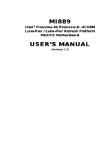
Board Dimensions
4
MI810 User’s Manual

INTRODUCTION
MI810 User’s Manual 5

INSTALLATIONS
6
MI810 User’s Manual
Installations
This section provides information on how to use the jumpers and
connectors on the MI810 in order to set up a workable system. The
topics covered are:
Installing the Memory ............................................................................ 7
Setting the Jumpers ................................................................................ 8
Connectors on MI810 .......................................................................... 12

INSTALLATIONS
Installing the Memory
The MI810 board supports two DDR2 memory socket for a maximum
total memory of 2GB in DDR2 memory type.
Installing and Removing Memory Modules
To install the DDR2 modules, locate the memory slot on the board and
perform the following steps:
1. Hold the DDR2 module so that the key of the DDR2 module align
with those on the memory slot.
2. Gently push the DDR2 module in an upright position until the clips of
the slot close to hold the DDR2 module in place when the DDR2
module touches the bottom of the slot.
3. To remove the DDR2 module, press the clips with both hands.
DDR2 Module
Lock Lock
Lock Lock
MI810 User’s Manual 7

INSTALLATIONS
8
MI810 User’s Manual
Setting the Jumpers
Jumpers are used on MI810 to select various settings and features
according to your needs and applications. Contact your supplier if you
have doubts about the best configuration for your needs. The following
lists the connectors on MI810 and their respective functions.
Jumper Locations on MI810 .................................................................. 9
JP1: LCD Panel Power Selection ......................................................... 10
JP2: ATX/AT Mode Select .................................................................. 10
JP3, JP4, JP5: RS232/422/485 (COM2) Selection .............................. 10
JP6: COM4 RS232 +5V / +12V Power Setting ................................... 11
JP7: COM3 RS232 +5V / +12V Power Setting ................................... 11
JP8: Clear CMOS Setting .................................................................... 11
J15: CompactFlash Slave/Master Selection ......................................... 11

INSTALLATIONS
Jumper Locations on MI810
Jumpers on MI810 ............................................................................ Page
JP1: LCD Panel Power Selection ........................................................ 10
JP2: ATX/AT Mode Select.................................................................. 10
JP3, JP4, JP5: RS232/422/485 (COM2) Selection .............................. 10
JP6: COM4 RS232 +5V / +12V Power Setting .................................. 11
JP7: COM3 RS232 +5V / +12V Power Setting .................................. 11
JP8: Clear CMOS Setting .................................................................... 11
J15: CompactFlash Slave/Master Selection ......................................... 11
MI810 User’s Manual 9

INSTALLATIONS
JP1: LCD Panel Power Selection
JP1 LCD Panel Power
3.3V
5V
JP2: ATX/AT Mode Select
JP2 ATX / AT
ATX mode
AT mode
JP3, JP4, JP5: RS232/422/485 (COM2) Selection
COM1/3/4 is fixed for RS-232 use only.
COM2 is selectable for RS232, RS-422 and RS-485.
The following table describes the jumper settings for COM2 selection.
COM2
Function
RS-232 RS-422 RS-485
Jumper
Setting
(pin closed)
JP5:
1-2
JP4:
3-5 & 4-6
JP3:
3-5 & 4-6
JP5:
3-4
JP4:
1-3 & 2-4
JP3:
1-3 & 2-4
JP5:
5-6
JP4:
1-3 & 2-4
JP3:
1-3 & 2-4
COM2 is jumper selectable for RS-232, RS-422 and RS-485.
Pin # Signal Name
RS-232 R2-422 RS-485
11 DCD TX- DATA-
13 RX TX+ DATA+
15 TX RX+ NC
17 DTR RX- NC
19 Ground Ground Ground
12 DSR RTS- NC
14 RTS RTS+ NC
16 CTS CTS+ NC
18 RI CTS- NC
20 NC NC NC
10
MI810 User’s Manual

INSTALLATIONS
JP6: COM4 RS232 +5V / +12V Power Setting
Pin #
Signal Name JP6 Signal Name
Pin #
1 RI
+12V 2
3 RI (Default) RI (Default) 4
5 RI +5V 6
COM4 Settings: Pin 1-2 short = +12V, Pin 5-6 short = +5V, Pin 3-4
Standard COM Port
JP7: COM3 RS232 +5V / +12V Power Setting
Pin #
Signal Name JP6 Signal Name
Pin #
1 RI
+12V 2
3 RI (Default) RI (Default) 4
5 RI +5V 6
COM3 Settings: Pin 1-2 short = +12V, Pin 5-6 short = +5V, Pin 3-4
Standard COM Port
JP8: Clear CMOS Setting
JP8 Setting
Normal
Clear CMOS
J15: CompactFlash Slave/Master Selection
J15 CF Setting
Master
Slave
MI810 User’s Manual 11

INSTALLATIONS
12
MI810 User’s Manual
Connectors on MI810
The connectors on MI810 allows you to connect external devices such as
keyboard, floppy disk drives, hard disk drives, printers, etc. The
following table lists the connectors on MI810 and their respective
functions.
Connector Locations on MI810 ........................................................... 13
FAN1: CPU Fan Power Connector ...................................................... 15
FAN2: System Fan Power Connector .................................................. 15
CN1: DC Jack (DC in, 12V or 19V) .................................................... 15
CN2: PS/2 Keyboard and PS/2 Mouse Connectors ............................. 15
CN3: VGA and DVI Connectors ......................................................... 16
CN4: USB5/6 Ports .............................................................................. 16
CN5: 10/100 RJ-45 and USB1/2 Ports ................................................ 16
CN6: GbE RJ-45 and USB3/4 Ports .................................................... 16
CN7: Audio Connector ........................................................................ 16
CN8, CN9: Serial ATA Connectors .................................................... 17
CN10: Mini PCI- E(x1) Connector (bottom side) ............................... 17
CN11: Compact Flash Connector (bottom side) .................................. 17
PCI1: PCI Slot (supports 2 Master) ..................................................... 17
PCIE_1: PCIE x1 Slot ......................................................................... 17
IDE1: IDE Connector .......................................................................... 17
J1, J4: LCD Backlight Connector ........................................................ 18
J2: HDD Power Connector (Output: Max. 2A) ................................... 18
J3: ATX_12V Connector ..................................................................... 18
J5: Power LED Connector ................................................................... 18
J6: Digital I/O ...................................................................................... 19
J7: COM1, COM2 Serial Ports ............................................................ 19
J8, J10: LVDS Connectors (1st channel, 2nd channel) ....................... 19
J9: System Function Connector ........................................................... 20
J11: COM3, COM4 Serial Ports .......................................................... 20
J12: Wake On LAN Connector ............................................................ 20
J13: USB7/8 Port Pin Header .............................................................. 20
J14: Audio Front Header ..................................................................... 21
J16: SPI Debug Tools Port (Factory use only) .................................... 21
J17: Smart Battery Connector .............................................................. 21
J18: SPDIF Out Connector .................................................................. 21
J19: Parallel Port .................................................................................. 21

INSTALLATIONS
Connector Locations on MI810
MI810 User’s Manual 13

INSTALLATIONS
14
MI810 User’s Manual

INSTALLATIONS
FAN1: CPU Fan Power Connector
FAN1 is a 3-pin header for the CPU fan. The fan must be 12V (Max.
500mA).
Pin # Signal Name
1 Ground
2 +12V
3 Rotation detection
FAN2: System Fan Power Connector
FAN2 is a 3-pin header for system fans. The fan must be 12V (Max.
500mA).
Pin # Signal Name
1 Ground
2 +12V
3 Rotation detection
CN1: DC Jack (DC in, 12V or 19V)
Remarks: CN1 and J3 cannot be connected at the same time.
CN2: PS/2 Keyboard and PS/2 Mouse Connectors
PS/2 Mouse
PS/2 Keyboard
Signal Name Keyboard Mouse Signal Name
Keyboard data 1 1 Mouse data
N.C. 2 2 N.C.
GND 3 3 GND
5V 4 4 5V
Keyboard clock 5 5 Mouse clock
N.C. 6 6 N.C.
MI810 User’s Manual 15

INSTALLATIONS
CN3: VGA and DVI Connectors
Signal Name Pin # Pin # Signal Name
Red 1 2 Green
Blue 3 4 N.C.
GND 5 6 GND
GND 7 8 GND
VCC 9 10 GND
N.C. 11 12 DDCDATA
HSYNC 13 14 VSYNC
DDCCLK 15
Signal Name Pin # Pin # Signal Name
DATA 2- 1 16 HOT POWER
DATA 2+ 2 17 DATA 0-
Shield 2/4 3 18 DATA 0+
DATA 4- 4 19 SHIELD 0/5
DATA 4+ 5 20 DATA 5-
DDC CLOCK 6 21 DATA 5+
DDC DATA 7 22 SHIELD CLK
VSYNC 8 23 CLOCK -
DATA 1- 9 24 CLOCK +
DATA 1+ 10
SHIELD 1/3 11
DATA 3- 12
DATA 3+ 13
DDC POWER 14
A GROUND 1 15
CN4: USB5/6 Ports
CN5: 10/100 RJ-45 and USB1/2 Ports
CN6: GbE RJ-45 and USB3/4 Ports
CN7: Audio Connector
16
MI810 User’s Manual
/