Dwyer RM Series User manual

Type
User manual

Dwyer RM Series: Versatile flowmeters for air, gas, and water applications. Rugged construction and simple operation make them ideal for a wide range of industrial uses.

Dwyer RM Series: Versatile flowmeters for air, gas, and water applications. Rugged construction and simple operation make them ideal for a wide range of industrial uses.

Series RM Rate-Master® Flowmeters
Specications - Installation and Operating Instructions
Bulletin F-43
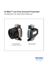
The Series RM Rate-Master® Flowmeters are furnished in three models (see Figure
2), each available in a broad array of ow ranges with direct reading scales for air, gas
or water. Installation, operation and maintenance are very simple. Only a few common-
sense precautions must be observed to assure long, trouble-free service.
Calibration
Each Rate-Master® Flowmeter is calibrated at the factory. If at any time during the
meter’s life, you wish to re-check its calibration, do so only with devices of certied
accuracy. DO NOT attempt to check a Rate-Master® Flowmeter with a similar
owmeter, as seemingly unimportant variations in piping and back pressure may
cause noticeable differences in the indicated reading. If in doubt, return your Rate-
Master® Flowmeter to the factory. Before proceeding with installation, check to be sure
you have the Rate-Master® owmeter model and ow range you require.
LOCATION: Temperature, Pressure, Atmosphere and Vibration: Rate-Master®
Flowmeters are exceptionally tough and strong. They are designed for use at
pressures up to 100 psi (6.89 bar) and temperatures up to 130°F (54°C).
DO NOT EXCEED THESE LIMITS! The installation should not be exposed to strong
chlorine atmospheres or solvents such as benzene, acetone, carbon tetrachloride, etc.
The mounting panel should be free of excessive vibration, as it may prevent the unit
from operating properly.
Inlet Piping Run: It is good practice to approach the owmeter inlet with as few
elbows and restrictions as possible. In every case, the inlet piping should be at least
as large as the connection to the owmeter; i.e.,1/8˝ Iron Pipe Size for RMA models
1/4˝ IPS for RMB models,1/2˝ IPS for RMC models. Length of inlet piping makes little
difference for normal pressure-fed owmeters.
For owmeters on vacuum air service, the inlet piping should be as short and open as
possible. This will allow operation near atmospheric pressure and thereby insure the
accuracy of the device. (Note: for vacuum air service, the ow control valve, if any,
should be on the discharge side of the owmeter. Either the TMV unit or a separate
in-line valve may be applied.).
Discharge Piping: As on the inlet, discharge piping should be at least as large as
the owmeter connection. Also, for pressure-fed owmeters on air or gas service, the
discharge piping should be as short and open as possible. This will allow operation
of the ow tube at near atmospheric pressure and insure the accuracy of the device.
This is of less importance on water or liquid owmeters, as the owing medium is
generally incompressible and moderate back pressure will not affect the accuracy of
the instrument as calibrated.
POSITIONING AND MOUNTING
All Rate-Master® Flowmeters must be mounted in a vertical position with inlet
connection at the bottom rear and outlet at the top rear.
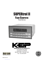
Bezel or Through-Panel Mounting: Make panel cutout using appropriate dimensions
from Figure 2. Flowmeter must t into panel freely without forcing or squeezing. Insert
the owmeter from the front of the panel and install the mounting clamps from the rear.
Insert and tighten the clamp bolts in the locations shown in Figure 3. Do not exceed
5 in./lbs. Make connections to inlet and outlet ports using pipe thread sealant tape to
avoid leakage. Avoid excess torque, which may damage the owmeter body.
DWYER INSTRUMENTS, INC.
P.O. BOX 373 • MICHIGAN CITY, INDIANA 46360, U.S.A.
Phone: 219-879-8000
Fax: 219-872-9057
www.dwyer-inst.com
RMC RMB-SSV RMA-TMV
Figure 1 Figure 2
A
BC
D
E
F
G
H
I
J
K
L
FULL OPEN
BACK
WIDTH
DIMENSIONS IN INCHES (CENTIMETERS)
Model RMA Model RMB Model RMC
A
B
C
D
E
F
G
H
I (OPEN)
J
K
L
4-9/16 [11.59]
3 [7.62]
1/8 NPT CONN.
1-5/8 [4.13]
10 - 32 Thds.
3/8 [.95]
1-1/16 [2.70]
1-3/16 [3.02]
11/16 [1.75]
61/64 [2.42]
1-3/8 [3.49]
3/4 [1.91]
4-13/16 [12.22]
1 [2.54]
8-1/2 [21.59]
6-7/16 [16.35]
1/4 NPT CONN.
3-15/16 [10.00]
1/4 - 20 Thds.
5/8 [1.59]
1-7/8 [4.76]
1-3/4 [4.45]
1 [2.54]
1-7/16 [3.65]
1-13/16 [4.60]
1-1/4 [3.18]
8-3/4 [22.23]
1-1/2 [3.81]
15 -1/8 [38.42]
12 -1/4 [31.12]
1/2 NPT CONN.
8-3/4 [22.23]
3/8 - 24 Thds.
1 [2.54]
2-3/4 [6.99]
2-1/2 [6.35]
1-7/16 [3.65]
1-31/32 [5.00]
2-1/2 [6.35]
2 [5.08]
15-3/8 [39.05]
2-1/4 [5.72]
PANEL CUTOUT FOR FLUSH MOUNTING
High
Wide
4-5/8 (11.75)
7/8 (2.22)
8-9/16 (21.75)
1-5/16 (3.33)
15 -3/16 (38.58)
2-1/16 (5.24)
PANEL HOLE SIZES FOR SURFACE MOUNTING
Pipe
Bolt
7/16 (1.11)
1/4 (0.64)
5/8 (1.59)
9/32 (0.71)
15/16 (2.38)
13/32 (1.03)
Rate-Master® Flowmeters are designed to provide satisfactory
long-term service when used with air, water or other compatible
media. Refer to factory for information on questionable gases or liquids. Avoid solutions
of acids, bases or salts having a pH below 5.0 or above 8.5. Caustic solutions,
antifreeze (ethylene glycol) and aromatic solvents should denitely not be used.
CAUTION
Surface Mounting: Drill appropriate holes in panel, using the dimensions shown in
Figure 2. Hold the owmeter in position in front of the panel and install the clamp bolts
from the rear. (The mounting clamps may be used as washers, if desired, by installing
them backwards or straightening them out.) Pipe up inlet and discharge following the
directions in the previous sections.
Surface Mounting on Piping Only: An alternate method of surface mounting,
omitting the clamp bolts and supporting the owmeter solely on the connecting piping,
is possible. For this method, extra-long or straight pipe threads should be used so
that nuts may be run onto the pipe and later tightened against the back of the panel to
retain the unit in proper position. Use appropriate hole layout in formation from Figure
2, but omit the small holes.
Surface Mounting on Piping Only Without Panel: For a temporary or laboratory
type installation, the panel may be omitted altogether and the owmeter installed
directly in rigid piping. Its light weight permits this without difculty.
OPERATION
To start system, open valve slowly to avoid possible damage. Control valves on SSV
models are turned clockwise to reduce ow, counter-clockwise to increase ow (valve
is designed for ow adjustment only, not intended to be used as an open/shut-off
valve). A nylon insert is provided in the threaded section of the valve stem to give a rm
touch to valve and to prevent change of setting due to vibration.
The performance of low range units used in air or gas applications may be affected by
static electricity. Excessive static charge may cause the ball oat to behave erratically
or provide a false reading. To ensure the proper function of the unit, the application
should be designed to minimize or dispel static electricity.
The standard technique for reading a Variable Area Flowmeter is to locate the highest
point of greatest diameter on the oat, and then align that with the theoretical center
of the scale graduation. In the event that the oat is not aligned with a grad, an
extrapolation of the oat location must be made by the operator as to its location
between the two closest grads. The following are some sample oats shown with
reference to the proper location to read the oat.
Variable Area Flowmeters used for gases are typically labeled with the prex “S” or
“N”, which represents “Standard” for English units or “Normal” for metric units. Use
of this prex designates that the owmeter is calibrated to operate at a specic set of
conditions, and deviation from those standard conditions will require correction for the
calibration to be valid. In practice, the reading taken from the owmeter scale must
be corrected back to standard conditions to be used with the scale units. The correct
location to measure the actual pressure and temperature is at the exit of the owmeter,
except when using the Top Mounted Valve under vacuum applications, where they
should be measured at the owmeter inlet. The equation to correct for nonstandard
operating conditions is as follows:
Q2 = Q1 x
Where: Q1 = Actual or Observed Flowmeter Reading
Q2 = Standard Flow Corrected for Pressure and Temperature
MOUNTING
BRACKET
SCREW 4
REQUIRED
Figure 3
Figure 4
Figure 7
Figure 5 Figure 5B
Figure 6 Figure 6B
P1 x T2
P2 x T1
P1 = Actual Pressure (14.7 psia + Gage Pressure)
P
2 = Standard Pressure (14.7 psia, which is 0 psig)
T1 = Actual Temperature (460 R + Temp °F)
T2 = Standard Temperature (530 R, which is 70°F)
Example: A owmeter with a scale of 10-100 SCFH Air. The oat is sitting at the 60
grad on the owmeter scale. Actual Pressure is measured at the exit of the meter as 5
psig. Actual Temperature is measured at the exit of the meter as 85°F.
Q2 = 60.0 x
Q2 = 68.5 SCFH Air
MAINTENANCE
The only maintenance normally required is occasional cleaning to assure reliable
operation and good oat visibility.
Disassembly: The owmeter can be disassembled for cleaning simply as follows:
1. Remove valve knob from RMB-SSV or RMC-SSV unit by pulling the knob forward.
It is retained by spring pressure on the stem half-shaft so that a gentle pull will
remove it. On RMA-SSV models, turn the valve knob counter-clockwise until the
threads are disengaged. Then withdraw the stem from the valve by gently pulling
on the knob.
2. Remove the four mounting bracket screws located in the sides of the owmeter.
See Figure 3. Pull the owmeter body gently forward away from the back plate to
avoid undue strain on the body. Leave the piping connections intact. There is no
need to disturb them. See Figure 4.
3. Threaded body style owmeters - Remove the slip cap with a push on a screwdriver
as shown in Figure 5. Remove the plug ball stop as shown in Figure 6 using allen
wrench sizes as follows: Model RMA - 1/4˝, Model RMB - 1/2˝ and Model RMC -
3/4˝ threadless body style owmeters - Release the plastic retaining clip with a
screw driver (Figure 5B), it will unclip from the valve body (TMV option) or the plug
ball stop, slide the clip back until the valve body or ball stop can be removed. The
clip will remain in the body for convenience. Using a screwdriver gently lift up on
the plug in the groove as shown in Figure 6B until the O-ring seal is released and
remove the plug. For the TMV option gently pull up on the valve knob to release the
valve body seals and remove the valve.
4. Take out the ball or oat by inverting the body and allowing the oat to fall into your
hand, as shown in Figure 7. (Note: It is best to cover the discharge port to avoid
losing the oat through that opening.)
Cleaning: The ow tube and owmeter body can best be cleaned with a little pure
soap and water. Use of a bottle brush or other soft brush will aid the cleaning. Avoid
benzene, acetone, carbon tetrachloride, alkaline detergents, caustic soda, liquid soaps
(which may contain chlorinated solvents), etc. Also, avoid prolonged immersion, which
may harm or loosen the scale.
Reassembly: Simply reverse steps 1 through 4 and place the owmeter back in
service. A little stopcock grease or petroleum jelly on the “Orings will help maintain a
good seal as well as facilitate assembly. No other special care is required.
(14.7 + 5) x 530
14.7 x (460 + 85)
Do not completely unscrew valve stem unless the owmeter is
unpressurized and drained of any liquid. Removal while in service
will allow gas or liquid to ow out the front of the valve body and could result in serious
personal injury. For applications involving high pressure and/or toxic gases or uids,
please contact factory for details.
CAUTION
Printed in U.S.A. 1/22 FR# 440197-00 Rev. 25©Copyright 2022 Dwyer Instruments, Inc.
DWYER INSTRUMENTS, INC.
P.O. BOX 373 • MICHIGAN CITY, INDIANA 46360, U.S.A.
Phone: 219-879-8000
Fax: 219-872-9057
www.dwyer-inst.com
NOTES
__________________________________________________________________________________________________________________________________________
__________________________________________________________________________________________________________________________________________
__________________________________________________________________________________________________________________________________________
__________________________________________________________________________________________________________________________________________
__________________________________________________________________________________________________________________________________________
__________________________________________________________________________________________________________________________________________
__________________________________________________________________________________________________________________________________________
__________________________________________________________________________________________________________________________________________
__________________________________________________________________________________________________________________________________________
__________________________________________________________________________________________________________________________________________
__________________________________________________________________________________________________________________________________________
__________________________________________________________________________________________________________________________________________
__________________________________________________________________________________________________________________________________________
__________________________________________________________________________________________________________________________________________
__________________________________________________________________________________________________________________________________________
__________________________________________________________________________________________________________________________________________
__________________________________________________________________________________________________________________________________________
__________________________________________________________________________________________________________________________________________
__________________________________________________________________________________________________________________________________________
__________________________________________________________________________________________________________________________________________
__________________________________________________________________________________________________________________________________________
__________________________________________________________________________________________________________________________________________
__________________________________________________________________________________________________________________________________________
__________________________________________________________________________________________________________________________________________
__________________________________________________________________________________________________________________________________________
  • Page 1 1
  • Page 2 2
  • Page 3 3
  • Page 4 4

Dwyer RM Series User manual

Type
User manual

Dwyer RM Series: Versatile flowmeters for air, gas, and water applications. Rugged construction and simple operation make them ideal for a wide range of industrial uses.

Ask a question and I''ll find the answer in the document

Finding information in a document is now easier with AI