Page is loading ...

The Series RMV II Rate-Master
®
flowmeters employ a target-
type design combined with a magnetic linkage driving a pointer
over a direct reading scale. This unique construction delivers ±5%
of full scale accuracy while enabling leakproof operation at pres-
sures to 3000 psig (206.7 bar). Solid machined brass meter body
is ideal for air or water flows. Dial face body fits standard 4-1/2˝
mounting hole layouts per ANSI B40.1. Inlet and outlet threads are
3/4˝ female NPT. A 1/2˝ reducing bushing is available at extra cost.
Scales are calibrated for air or water at standard conditions.
CALIBRATION
All standard RMV II Rate Master
®
flowmeters are calibrated at the
factory for use with scale in a vertical position and should be
installed that way for maximum accuracy.
The unit will normally retain its accuracy tolerance for the useful life
of the device. If you want to check the accuracy, do so only with
instruments of certified accuracy. Do not attempt to check accura-
cy with other flowmeters piped in series. Even minor variations in
piping and back pressure can cause significant differences in indi-
cation. If in doubt, return the flowmeter to the factory for a calibra-
tion check.
LOCATION
Select a location where the flowmeter can be easily read and ambi-
ent temperature will not exceed 200°F (93°C). The mounting sur-
face and piping to the flowmeter should be free from excessive
vibration. If pulsing flow or vibration causes excessive pointer oscil-
lation, contact the factory for ways to provide additional dampen-
ing.
Because the device operates through a magnetic coupling system,
magnetic material located near the brass flow block can affect
accuracy. To minimize the effect of outside interference, keep mag-
netic materials at least 3 inches (7.6 cm) away from unit.
Inlet Piping
It is a good practice to approach the flowmeter with as few
elbows, restrictions and size changes as possible. Inlet piping
should be as close to the flowmeter connection size as possible to
avoid turbulence which can occur with drastic size changes. The
length of inlet piping has little effect on normal pressure fed
flowmeters.
For vacuum service the inlet piping should be as short and open
as possible to allow operation at or near atmospheric pressure,
thus maintaining the accuracy of the device. Note that for vacuum
service, any flow control valve must be installed on the discharge
side of the flowmeter.
Outlet Piping
Piping to the outlet should be at least as large as the inlet con-
nection. For pressure fed flowmeters on air or gas service, the pip-
ing should be as large and short as possible. This is so pressure
within the device will be at or near atmospheric for maximum
accuracy. This is less important on water or liquid flowmeters since
the flowing media is generally not compressible and therefore back
pressure will not affect the calibration of the instrument.
Series RMV II Rate-Master
®
Flowmeter
Specifications - Installation and Operating Instructions
Bulletin F-59
SPECIFICATIONS
Service: Compatible gases & liquids & oils.
Wetted Materials: Brass, 302 SS, sintered barium ferrite,
polyacetyl.
Temperature Limit: 200°F (93°C).
Pressure Limit: 3000 psig (206 bar).
Pressure Drop: 0-5 GPM: 3.2 PSID; 0-10 GPM: 5.3
PSID; 0-20 GPM: 10.4 PSID.
Accuracy: ±5% of full scale.
Size: Diameter dial face 4.5˝ (114.3 mm)
Process Connections: 3/4˝ female NPT.
Weight: 2 lb, 14 oz (1.3 kg).
DWYER INSTRUMENTS, INC.
P.O. BOX 373 • MICHIGAN CITY, IN 46361 U.S.A.
Phone: 219/879-8000 www.dwyer-inst.com
Fax: 219/872-9057 e-mail: info@dwyer-inst.com
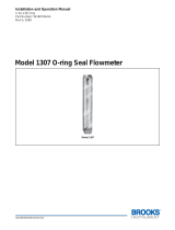
5-7/8 DIA.
[149.2]
120˚
TYP.
(3) 7/32 DIA. (5.556)
HOLES ON 5-3/8 DIA.
(136.5) BOLT CIRCLE
4.440
[112.8]
3/4⬙ NPT
1.250
[31.75]
1.0
[25.4]
.350
[8.890]
4.645
[118.0]
1.300
[33.02]
*FITS IN ANSI STANDARD 4.940 [125.5] PANEL CUTOUT.
F-59:F-59 8/19/09 8:30 AM Page 1

Zero Adjustment
Standard Series RMV II flowmeters are calibrated and zeroed at
the factory with the scale in a vertical position. If the instrument is
used in any other position, it must be rezeroed for maximum accu-
racy.
To re-zero, insert a small screwdriver blade into the gap of the
cover retaining ring near the bottom of the flowmeter face. Pry one
end free and completely remove the ring from its groove. Holding
one hand on the cover, turn the unit over until cover drops free into
your palm. Be careful to avoid scratching the cover.
In the lower right area of the scale there is a 1/8˝ dia. knurled knob
which is used to adjust the zero reading. Turn it clockwise to move
pointer upscale or counter-clockwise to move it downscale. Make
these adjustments with the flowmeter in the position in which it will
be mounted. If the pointer moves downscale while turning the
knob clockwise, continue to turn the knob clockwise until upscale
pointer movement occurs. Re-zero as described above.
After adjustment, make sure the O-ring is properly positioned in its
groove and replace the cover. Next, replace the retaining ring. Start
at one end and carefully press it into place working in a counter-
clockwise direction. If ring is difficult to replace by hand, it may be
necessary to use a small screwdriver blade to guide it in. Be care-
ful to avoid scratching the cover.
In-Line Mounting
RMV II flowmeters can be installed in-line supported only by the
piping. Be sure to use a wrench on the brass meter body when
tightening to avoid application of torque to the plastic dial housing.
Permanent damage can result.
Flush Mounting
To flush panel mount, cut a 4.94˝ (125 mm) mounting hole and drill
three 7/32˝ (5.56 mm) bolt holes on a 5-3/8˝ (137 mm) circle as
shown in the drawing on the front of this bulletin. Attach flowmeter
with 3/16˝ bolts of appropriate length.
OPERATION
If flowing media is likely to be dirty, install a 50 micron filter
upstream from the flowmeter. Once all connections are complete,
introduce flow slowly to avoid possible damage. With liquid flow, it
may be necessary to purge air from the system before reading sta-
bilize. No lubrication or periodic servicing is required. Keep case
exterior, including front cover, clean for best visibility.
Variable Area Flowmeters used for gases are typically labeled with
the prefix “S” or “N”, which represents “Standard” for English units
or “Normal” for metric units. Use of this prefix designates that the
flowmeter is calibrated to operate at a specific set of conditions,
and deviation from those standard conditions will require correc-
tion for the calibration to be valid. In practice, the reading taken
from the flowmeter scale must be corrected back to standard con-
ditions to be used with the scale units. The correct location to
measure the actual pressure and temperature is at the exit of the
flowmeter, except under vacuum applications where they should
be measured at the flowmeter inlet. The equation to correct for
nonstandard operating conditions is as follows:
Q
2
= Q
1
x P
1
x T
2
P
2
x T
1
Where: Q
1
= Actual or Observed Flowmeter Reading
Q
2
= Standard Flow Corrected for Pressure and
Temperature
P
1
= Actual Pressure (14.7 psia + Gage Pressure)
P
2
= Standard Pressure (14.7 psia, which is 0 psig)
T
1
= Actual Temperature (460 R + Temp °F)
T
2
= Standard Temperature (530 R, which is 70°F)
Example: A flowmeter with a scale of 10-100 SCFH Air. The float
is sitting at the 60 grad on the flowmeter scale. Actual Pressure is
measured at the exit of the meter as 5 psig. Actual Temperature is
measured at the exit of the meter as 85°F.
Q
2
= 60.0 x (14.7 + 5) x 530
14.7 x (460 + 85)
Q
2
= 68.5 SCFH Air
More Information
Contact factory for additional information including conversion
curves, correction factors and other types and ranges of Dwyer
Instruments, Inc. flowmeter.
©Copyright 2009 Dwyer Instruments, Inc.
Printed in U.S.A. 8/09
FR# 50-440956-00 Rev. 2
DWYER INSTRUMENTS, INC.
P.O. BOX 373 • MICHIGAN CITY, IN 46361 U.S.A.
Phone: 219/879-8000 www.dwyer-inst.com
Fax: 219/872-9057 e-mail: info@dwyer-inst.com
F-59:F-59 8/19/09 8:30 AM Page 2
/