Page is loading ...

Series VFCR Visi-Float
®
Flowmeter with Roto-Gear Valve Technology
Specications - Installation and Operating Instructions
Bulletin F-VFCR
The innovative Series VFCR Visi-Float
®
Acrylic Flowmeter with Roto-Gear
Technology is a direct reading variable area owmeter with scales for liquid or gas
applications. Roto-gear valve technology permits full open to close adjustment while
maintaining ne ow control of the process media in one valve design. Installation,
operation, and maintenance are simple ensuring a long, accurate, and trouble-free
operation life.
CALIBRATION
All owmeters are calibrated at the factory and normally will remain within their accuracy
tolerance for the life of the device. If at any time you wish to re-check its calibration, do
so only with instruments or equipment of certied accuracy. Do not attempt to check
the Visi-oat
®
owmeter with a similar owmeter as even minor variations in piping
and back pressure can cause signicant differences between the indicated and actual
readings. If in doubt, your owmeter may be returned to the factory for evaluation.
LOCATION
Select a location where the owmeter can be easily read and where the temperature
will not exceed 120°F (48°C). The mounting surface and piping to the owmeter
should be free from vibration which could cause fatigue of ttings or mounting inserts.
Piping must be carefully arranged and installed to avoid placing stress on ttings and/
or owmeter body. Damage due to contact with incompatible gases or liquids is not
covered by warranty. Compatibility should be carefully determined before placing in
service.
PIPING
Inlet Piping
It is good practice to approach the owmeter inlet with as few elbows, restrictions and
size changes as possible. Inlet piping should be as close to the owmeter connection
size as practical to avoid turbulence which can occur with drastic size changes. The
length of inlet piping has little effect on normal pressure fed owmeters.
Discharge Piping
Piping on the discharge side should be at least as large as the owmeter connection.
For pressure fed owmeters on air or gas service, the piping should be as short and
open as possible. This allows operation at or near atmospheric pressure and assures
the accuracy of the device. This is less important on water or liquid owmeters since
the owing medium is generally incompressible and back pressure will not affect the
calibration of the instrument.
POSITION AND MOUNTING
All Visi-Float
®
owmeters must be installed in a vertical position with the inlet
connection at the bottom and outlet at the top.
Surface Mounting
Drill three holes in panel using dimensions shown in dimensional drawing. Holes
should be large enough to accommodate #10 - 32 machine screws. Drill two additional
holes for clearance of ttings. Install mounting screws of appropriate length from rear.
Mounting screws must not be longer than the panel thickness plus 3/8˝ (9.66 mm),
or the screw will hit the plastic and may damage the meter. The screws will require
additional force during the initial installation, since the insert boots are of a collapsed
thread type and must be expanded into the plastic for the knurled surface to take
hold. Insert boots will not have the proper 10-32 threads until the rst screw has been
inserted to expand the boot. Use pipe thread sealant tape or pipe thread sealant to
insure against leakage.
CAUTION: Do not overtighten ttings or piping into ttings. Maximum recommended
torque is 10 Ft-Lb (13.56 N-m). Hand tighten only.
CAUTION: Do not overtighten the valve knob. Overtightening the valve beyond a
torque rating of 0.25 Ft-Lb (0.34 N-m) may result in valve misalignment and alteration.
Hand tighten only.
SPECIFICATIONS
Service: Compatible gases and liquids.
Wetted Materials: Body: Acrylic plastic; O-ring: Buna-N (optional uoroelastomer);
Valve: Delrin
®
; Float: Stainless steel; Float stop: Polyolen (range no. 141 Polyolen
and PVC); Float rod: 18-8 SST; Fittings: PVC (VFCRII Delrin
®
).
Temperature Limit: 120°F (48°C).
Pressure Limit: 100 psig (6.9 bar).
Accuracy: 2% of FS.
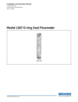
Process Connection: VFCR: 1˝ female NPT back connections; VFCRII: 1˝ male
NPT back connections.
Scale Length: 5˝ (127 mm).
Mounting Orientation: Mount in vertical position.
Weight: 25.6 oz (0.73 kg).
DWYER INSTRUMENTS, INC.
P.O. BOX 373 • MICHIGAN CITY, INDIANA 46360, U.S.A.
Phone: 219/879-8000
Fax: 219/872-9057
www.dwyer-inst.com
e-mail: [email protected]
®
1-1/8
[28.58]
10-1/2
[266.70]
1-3/4
[44.45]
3
[76.20]
4-1/2
[114.30]
2-7/8
[2.93]
VFCR ROUND
FEMALE
1-1/2 NPT
8-1/2
[215.90]
1-1/2
[38.10]
1-1/8
[28.58]
1
[25.40]
2 NOM
[50.80]
VFCRII
HEX
1/2 [12.70]
7/8
[23.81]
1/2
[14.28]
VFCRII
ROUND
3/8 [10.31]
VFCRII
HEX
MALE 1-1/2
NPT/BSPT
VFCR Left with 1˝ female
NPT Connections
VFCRII with 1˝ male
NPT Connections

OPERATION
Once all connections are complete, introduce ow as slowly as possible to avoid
possible damage. With liquids, make sure all air has been purged before taking
readings. Once the oat has stabilized, read ow rate by sighting across the largest
diameter of the oat to the scale graduations on the face of the device. The standard
technique for reading a Variable Area Flowmeter is to locate the highest point of
greatest diameter on the oat, and then align that with the theoretical center of the
scale graduation. Refer to Figure 1 for proper oat installation. In the event that the
oat is not aligned with a graduation, an extrapolation of the oat location must be
made by the operator as to its location between the two closest grads. The following
are some sample oats shown with reference to the proper location to read the oat.
The equation to correct for nonstandard operating conditions is as follows:
Where: Q1 = Actual or Observed Flowmeter Reading
Q2 = Standard Flow Corrected for Pressure and Temperature
P1 = Actual Pressure (14.7 psia + Gage Pressure)
P2 = Standard Pressure (14.7 psia, which is 0 psig)
T1 = Actual Temperature (460 R + Temp °F)
T2 = Standard Temperature (530 R, which is 70°F)
Example: A owmeter with a scale of 10-100 SCFH Air. The oat is sitting at the 60
grad on the owmeter scale. Actual Pressure is measured at the exit of the meter as 5
psig. Actual Temperature is measured at the exit of the meter as 85°F.
Q
2 = 68.5 SCFH Air
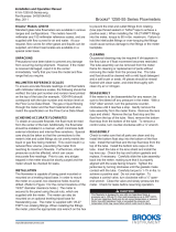
Removal of Valve Cartridge
Easily remove the valve cartridge by referring to Figure 2 below and following the
steps below:
1. Turn the knob counterclockwise until the valve is completely open. Then close the
valve half turn (Allow the cartridge (F) to easily disengage.)
2. Remove knob (A)
3. Remove the clip (B)
4. Unscrew the tting (H)
5. Remove the wave washer (G)
6. Turn the acrylic body with the threaded opening (C) face down and apply a gentle
force on stem (D) from the opposite side
7. The cartridge (F) will easily slide out from the threaded opening
Re-assembly of Valve Cartridge
Reinstall a valve cartridge by referring to Figure 2 and following the steps below:
1. Insert the stem (D) into the cartridge (F) to engage with the gear and clip (E).
2. Turn stem (D) counterclockwise until the clip (E) contacts the cartridge (F)
3. Move the cartridge (F) with clip and stem into the threaded opening (C)
4. Inster wave washer (G)
4. Thread tting (H) into threaded opening (C)
5. Insert clip (B) on stem (D)
6. Insert knob (A) onto clip (B) that should already be on stem (D)
Disassembly of Float Rod
The owmeter can be completely disassembled by removing the connection ttings
and top plug. The guide rodis threaded into the top plug on one end and the rod guide
on the other end. When disassembling, be careful not to lose the plastic tubing which
serve as oat stops. Note the orientation of the oat before disassembly.
Re-assembly of Float Rod
Easily reinstall the oat rod by referring to Figure 3 and following the steps below:
1. Reassemble the top tting and oat rod, ensuring the oat is properly oriented.
See Figure 1 for oat orientation.
2. Turn the top tting (K) to the fully tightened position. For models VFCR-141,
VFCR-142, VFCR-151 and VFCR-152, skip step 3 below.
3. Turn top tting counter-clockwise (loosening) until the 4 alignment notches (L) on
the bottom of the guide rod holder are positioned to the side, front, and back
surfaces of the acrylic meter body while ensuring minimal movement of the top
tting. The orientation of the notches is essential for optimal meter performance.
Note: A light coat of grease on the O-rings will help maintain a good seal as well as
ease assembly
ADDITIONAL INFORMATION
For additional owmeter application information, conversion curves, correction
factors and other data covering the entire line of owmeters, please request a Dwyer
Instruments, Inc. full-line catalog available on our website.
MAINTENANCE/REPAIR
Upon nal installation of the Series VFCR, only routine maintenance is required.
The Series VFCR should be returned if repair is needed. Field repair should not be
attempted and may void warranty.
Cleaning
The owmeter body and all other parts can be cleaned by washing in a mild soap and
water solution. A soft bristle bottle brush will simplify cleaning of the ow tube. Avoid
ammonia, benzene, acetone, carbon tetrachloride, gasoline, alkaline detergents,
caustic soda, liquid soaps, (which may contain chlorinated solvents), and avoid
prolonged immersion.
WARRANTY/RETURN
Refer to “Terms and Conditions of Sale” in our catalog and on our website. Contact
customer service to receive a Return Material Authorization number before shipping
the product back for repair. Be sure to include a brief description of the problem plus
any additional application notes.
Figure 1
H
G
F
E
D
C
B
A
Figure 2
MODEL CHART
Model Description
A-VFCR-KITB
A-VFCR-KITV
Replacement valve cartridge buna O-rings
Replacement valve cartridge uorelastomer O-rings
Q
2 = Q1 x
P1 x T2
P2 x T1
Q2 = 60.0 x
(14.7 + 5) x 530
14.7 x (460 + 85)
Delrin
®
is a registered trade mark of E. I. du Pont de Nemours and Company
(L) ALIGNMENT NOTCHES
K
(L) ALIGNMENT
NOTCH
TO
P SIDE VIEW
Figure 3
DWYER INSTRUMENTS, INC.
P.O. BOX 373 • MICHIGAN CITY, INDIANA 46360, U.S.A.
Phone: 219/879-8000
Fax: 219/872-9057
www.dwyer-inst.com
e-mail: [email protected]
©Copyright 2018 Dwyer Instruments, Inc. Printed in U.S.A. 7/18 FR# 444315-00 Rev. 4
/