Page is loading ...

Series VF Visi-Float
®
Flowmeters
Specications - Installation and Operating Instructions
Bulletin F-33
The Series VF Visi-Float
®
Flowmeters are furnished in two models (see drawing
above) each available in a broad choice of ow ranges with direct reading scales for
air, gas or water. Installation, operation and maintenance are very simple and only a
few common sense precautions must be observed to assure long, trouble-free service.
CALIBRATION
Each owmeter is calibrated at the factory. If at any time during the meter’s life, you
wish to recheck its calibration, do so only with devices of certied accuracy. DO NOT
attempt to check the Visi-Float
®
Flowmeter with a similar owmeter as seemingly
unimportant variations in piping and back pressure may cause noticeable differences
in the indicated reading. If in doubt, return your owmeter to the factory. Before
proceeding with the installation of your Visi-Float
®
Flowmeter, check to be sure you
have the model and ow range you require.
LOCATION
Temperature, Pressure, Atmosphere, and Vibration:
Visi-Float
®
Acrylic Flowmeters are exceptionally tough and strong. They are designed
for use at pressures up to 100 psi (7 bar) and temperatures up to 150°F (66°C).
DO NOT EXCEED THESE LIMITS! The installation should not be exposed to strong
chlorine atmospheres or solvents such as benzene, acetone, carbon tetrachloride, etc.
The mounting panel should be free of excessive vibration since it may prevent the unit
from operating properly.
Inlet Piping Run: It is good practice to approach the owmeter inlet with as few
elbows and restrictions as possible. In every case the inlet piping should be at least as
large as the connection to the owmeter i.e. 1/8˝ Iron Pipe Size. Length of inlet piping
makes little difference for normal pressure fed owmeters.
For ow meters on vacuum air service the inlet piping should be as short and open as
possible. This will allow operation near atmospheric pressure and thereby insure the
accuracy of the device. (Note that for vacuum air service the ow control valve if any,
should be on the discharge side of the owmeter. Either the TMV unit or a separate in
line valve may be applied.)
Discharge Piping: As on the inlet, discharge piping should be at least as large as the
owmeter connection. In addition, for pressure fed owmeters on air or gas service the
discharge piping should be as short and open as possible. This will allow operation
of the ow tube at near atmospheric pressure and insure the accuracy of the device.
This is of less importance on water or liquid owmeters since the owing medium is
generally incompressible and moderate back pressure will not affect the accuracy of
the instrument as calibrated.
POSITION AND MOUNTING
All Visi-Float
®
Flowmeters must be mounted in a vertical position with the inlet
connection at the bottom and outlet at the top.
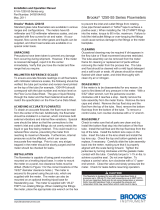
Surface Mounting: Drill appropriate holes in panel using the dimensions shown in
the drawing above. Hold the owmeter in position in front of the panel and install the
mounting screws through the panel from the rear. Mounting screws must not be longer
than the panel thickness plus 1/4˝, or the screw will hit the plastic and may damage
the meter. The screws will require additional force during the initial installation, since
the insert boots are of a collapsed thread type and must be expanded into the plastic
for the knurled surface to take hold. Insert boots will not have the proper 10-32 threads
until the rst screw has been inserted to expand the boot. Pipe up inlet and discharge
using pipe thread sealant tape or pipe thread sealant to insure against leakage.
SPECIFICATIONS
Service: Compatible gases and liquids.
Wetted Materials: Body: Acrylic plastic; O-ring: Buna-N (uoroelastomer available);
Metal parts: brass standard, SS optional; Float: SS, black glass, aluminum, K monel
depending on range.
Temperature and Pressure Limits: Without valve: 100 psig (6.9 bar) @ 150°F
(65°C); 150 psig (10 bar) @ 100°F (38°C); With valve: 100 psig (6.9 bar) @ 120°F
(48°C).
Accuracy: VFA = 5% FS; VFB= 3% FS.
Process Connection: 1/8˝ female NPT. VFB ranges 85 and 86 have 1/4˝ NPT back
connections or 3/8˝ NPT end connections. These ranges not available with brass
valves.
Scale Length: VFA 2˝ typical length; VFB 4˝ typical length.
Mounting Orientation: Mount in vertical position.
Weight: VFA: 4.0-4.8 oz (.11-.14 kg). VFB: 7.2-8.8 oz (.20-.25 kg).
A
B
C
D
E
F
M
I
N
K
L
FULL OPEN
M
Model VFB Model VFA-SSV
DIMENSIONS - FLOWMETER
Model VFA Model VFB
A
B
C
D
E
F
I
K
L
M
N
4 [101.6]
3 [76.20]; 1/8 NPT conn.
1-5/8 [41.28]; 10-32 thd
1/2 [12.70]
1-3/16 [30.16]
1-1/4 [31.75]
2-1/16 [52.39]; Open
4-3/32 [104.0]
1 [25.40]
7/8 [22.23] ; 1/8 NPT
3/32 [2.381]
6-1/2 [165.1]
5-1/2 [139.7]; 1/8 NPT conn.
3-1/2 [88.90]; 10-32 thd
1/2 [12.70]
1-1/2 [38.10]
1-1/4 [31.75]
2-1/16 [52.39] ; Open
6-11/16 [169.9]
1-3/8 [34.93]
7/8 [22.23]; 1/8 NPT
3/32 [2.381]
®
DWYER INSTRUMENTS, INC.
P.O. BOX 373 • MICHIGAN CITY, INDIANA 46360, U.S.A.
Phone: 219/879-8000
Fax: 219/872-9057
www.dwyer-inst.com
e-mail: [email protected]

Printed in U.S.A. 2/19 FR# 440241-00 Rev. 7©Copyright 2019 Dwyer Instruments, Inc.
DWYER INSTRUMENTS, INC.
P.O. BOX 373 • MICHIGAN CITY, INDIANA 46360, U.S.A.
Phone: 219/879-8000
Fax: 219/872-9057
www.dwyer-inst.com
e-mail: [email protected]
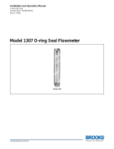
RANGE CHART - VFA 2˝ SCALE - POPULAR RANGES
Range No. SCFH Air Range No. LPM Air
1
2
3
4
5
6
7
8
9
.1 to 1
.2 to 2
.6 to 5
1 to 10
2 to 20
4 to 30
5 to 50
10 to 100
20 to 200
21
22
23
24
25
26
27
.06 to 0.5
.15 to 1
.6 to 5
1 to 10
3 to 25
6 to 50
10 to 100
Range No. CC/Min. Water Range No. GPH Water
32
33
34
6 to 50
10 to 100
20 to 200
41
42
43
44
.6 to 5
2 to 10
3 to 20
8 to 40
RANGE CHART - VFB 4˝ SCALE - POPULAR RANGES
Range No. SCFH Air Range No. LPM Air
50
91
51
52
53
54
55
.3 to 3
1 to 10
2 to 20
4 to 40
10 to 100
15 to 150
20 to 200
65
66
67
68
69
.2 to 4
1 to 10
1 to 20
3 to 30
4 to 40
Range No. CC/Min. Water
82 2 to 30
Range No. SCFM Air Range No. GPH Water
90 .3 to 3 80
83
81
.5 to 12
1 to 20
6 to 60
Range No. CC/Min. Air
60 100 to 1000
Range No. GPM Water
85
86
.2 to 2
.5 to 5
Surface Mounting on Piping Only: An alternate method of surface mounting is
by omitting the mounting screws and supporting the Visi-Float
®
Flowmeter on the
connecting piping only. For this method extra long or straight pipe threads should be
used so that nuts may be run onto the pipe and later tightened against the back of the
panel to retain the unit in proper position. Use the appropriate hole layout information
from the drawing on the previous page, but omit the small holes.
Mounting on Piping Only Without Panel: For the temporary or laboratory type
installation, the panel may be omitted altogether and the owmeter installed directly in
rigid piping. Its light weight permits this without difculty.
OPERATION
To start system, open the valve slowly to avoid possible damage. Control valves on BV
and SSV models are turned clockwise to reduce ow, counter clockwise to increase
ow (valve is designed for ow adjustment only, not intended to be used as an open/
shut-off valve). A nylon insert is provided in the threaded section of the valve stem to
give a rm touch to the valve and to prevent change of setting due to vibration.
The performance of low range units used in air or gas applications may be affected by
static electricity. Excessive static charge may cause the ball oat to behave erratically
or provide a false reading. To ensure the proper function of the unit, the application
should be designed to minimize or dispel static electricity.
The standard technique for reading a Variable Area Flowmeter is to locate the highest
point of greatest diameter on the oat, and then align that with the theoretical center
of the scale graduation. In the event that the oat is not aligned with a grad, an
extrapolation of the oat location must be made by the operator as to its location
between the two closest grads. The following are some sample oats shown with
reference to the proper location to read the oat.
Variable Area Flowmeters used for gases are typically labeled with the prex “S” or
“N”, which represents “Standard” for English units or “Normal” for metric units. Use
of this prex designates that the owmeter is calibrated to operate at a specic set of
conditions, and deviation from those standard conditions will require correction for the
calibration to be valid. In practice, the reading taken from the owmeter scale must
be corrected back to standard conditions to be used with the scale units. The correct
location to measure the actual pressure and temperature is at the exit of the owmeter,
except under vacuum applications where they should be measured at the owmeter
inlet. The equation to correct for nonstandard operating conditions is as follows:
Q
2 = Q1 x
Where: Q
1 = Actual or observed owmeter reading
Q
2 = Standard ow corrected for pressure and temperature
P
1 = Actual pressure (14.7 psia + gage pressure)
P
2 = Standard pressure (14.7 psia, which is 0 psig)
T
1 = Actual temperature (460 R + temp °F)
T
2 = Standard temperature (530 R, which is 70°F)
Example: A owmeter with a scale of 10-100 SCFH Air. The oat is sitting at the 60
grad on the owmeter scale. Actual Pressure is measured at the exit of the meter as 5
psig. Actual Temperature is measured at the exit of the meter as 85°F.
Q
2 = 60.0 x
Q
2 = 68.5 SCFH Air
MAINTENANCE
The only maintenance normally required is occasional cleaning to assure reliable
operation and good oat visibility.
Disassembly: The owmeter can be disassembled for cleaning by simply
disconnecting the piping, dismounting the unit from the panel and removing the top-
plug-ball stop. Take out the ball or oat by inverting the body and allowing the oat to
fall into your hand. (Note: It is best to cover the discharge port to avoid losing the oat
through that opening.) When removing the oat guide assembly on VFB models 85
and 86, be careful not to lose the short pieces of plastic tubing on both ends of the
guide which serve as oat stops.
Cleaning: The ow tube and owmeter body can best be cleaned with a little pure
soap and water. Use of a bottle brush or other soft brush will aid the cleaning. Avoid
benzene, acetone, carbon tetrachloride, alkaline detergents, caustic soda, liquid
soaps (which may contain chlorinated solvents), etc. and avoid prolonged immersion.
Reassembly: Reinstall the oat, remount, connect and place the unit back in service.
A little stop cock grease or petroleum jelly on the “O”rings will help maintain a good
seal as well as facilitate assembly. No other special care is required.
For VFB models 85 and 86, rst install the lower tting, next the oat guide and oat
and nally the upper tting and plug. Be certain that both ends of the oat guide are
properly engaged and the oat is correctly oriented.
ADDITIONAL INFORMATION
For additional owmeter application information, conversion curves, factors and other
data covering the entire line of Dwyer Instruments, Inc. full-line catalog.
Do not completely unscrew valve stem unless owmeter is
unpressurized and drained of any liquid. Removal while in service
will allow gas or liquid to ow out front of valve body and could result in serious personal
injury. For applications involving high pressure and/or toxic gases or uids, special
non-removable valves are available on special order. Contact factory for details.
CAUTION
P
1 x T2
P
2 x T1
(14.7 + 5) x 530
14.7 x (460 + 85)
/