Page is loading ...

Commissioning Instruction CI/FAM3200-EN Rev. B
FAM3200
Armored Variable Area Purgemeter
Measurement made easy

2 CI/FAM3200-EN Rev. B | FAM3200
Short product description
A
rmored Variable Area Purgemeter for flow measurement of
fluids and gases.
Further information
A
dditional documentation on FAM3200 is available to
download free of charge at www.abb.com/flow.
A
lternatively simply scan this code:
Manufacturer
A
BB Automation Products GmbH
Measurement & Analytics
Dransfelder Str. 2
37079 Göttingen
Germany
Tel: +49 551 905-0
Fax: +49 551 905-777
Customer service center
Tel: +49 180 5 222 580
Mail: [email protected]
Change from one to tw o columns

FAM3200 | CI/FAM3200-EN Rev. B 3
Contents
1 Safety ............................................................................... 4
1.1 General information and instructions .................... 4
1.2 Warnings ............................................................. 4
1.3 Intended use ........................................................ 4
1.4 Improper use ....................................................... 5
1.5 Warranty provisions ............................................. 5
2 Use in potentially explosive atmospheres ..................... 6
2.1 Ex-marking .......................................................... 6
2.2 Temperature data ................................................ 6
2.3 Installation ........................................................... 6
2.3.1 Electrical connections .......................................... 6
2.4 Limit value tables ................................................. 7
3 Functional description .................................................... 8
4 Product identification ...................................................... 8
4.1.1 Name plate .......................................................... 8
4.1.2 Factory plate ........................................................ 9
5 Transport and storage .................................................... 9
5.1 Inspection ............................................................ 9
5.2 Transport ............................................................. 9
5.3 Storage ............................................................... 9
5.4 Returning devices ................................................ 9
6 Installation ..................................................................... 10
6.1 Safety instructions ............................................. 10
6.2 Installation conditions ......................................... 10
6.2.1 General .............................................................. 10
6.2.2 Installation recommendations ............................. 10
6.2.3 Pressure chambers and collecting tanks ............ 10
6.2.4 Sensor insulation ............................................... 10
6.2.5 Heat tracing ....................................................... 11
6.3 Operating conditions .......................................... 11
6.3.1 Pressure loss ..................................................... 11
6.3.2 Prevention of compression oscillations when
measuring gases ............................................... 11
6.3.3 Pressure shocks ................................................ 11
6.3.4 Solids content in the measuring medium ............ 12
6.4 Installation ......................................................... 12
6.4.1 General information ............................................ 12
6.4.2 Flowmeter installation ......................................... 12
6.5 Electrical connections ........................................ 12
6.5.1 Analog indicator with alarm signaling unit ........... 12
6.5.2 Switching amplifier ............................................. 13
6.5.3 Analog indicator with transmitter ........................ 13
7 Commissioning .............................................................. 13
7.1 Adjusting the alarm signalling unit....................... 13
7.2 Operating instructions ........................................ 13
8 Maintenance / Repair .................................................... 14
8.1 Spare parts ........................................................ 14
8.2 Cleaning ............................................................ 14
8.2.1 Disassembly of the meter tube ........................... 14
8.3 Returning devices .............................................. 15
9 Recycling and disposal ................................................. 15
9.1 Dismounting ...................................................... 15
9.2 Disposal ............................................................. 16
10 Specifications ................................................................ 16
10.1 Material load ...................................................... 16
10.2 Measuring range table ....................................... 17
10.2.1 Model
FAM3220 / FAM3250 / FAM3225 / FAM3255,
variable area and armored .................................. 17
10.2.2 Model FAM3225 / FAM3255, conical float and
orifice plate ........................................................ 18
11 Additional documents ................................................... 18
12 Appendix ....................................................................... 19
12.1 Return form ....................................................... 19

4 CI/FAM3200-EN Rev. B | FAM3200
1 Safety
Change from one to tw o columns
1.1 General information and instructions
These instructions are an important part of the product and
must be retained for future reference.
Installation, commissioning, and maintenance of the product
may only be performed by trained specialist personnel who
have been authorized by the plant operator accordingly. The
specialist personnel must have read and understood the
manual and must comply with its instructions.
For additional information or if specific problems occur that are
not discussed in these instructions, contact the manufacturer.
The content of these instructions is neither part of nor an
amendment to any previous or existing agreement, promise or
legal relationship.
Modifications and repairs to the product may only be
performed if expressly permitted by these instructions.
Information and symbols on the product must be observed.
These may not be removed and must be fully legible at all
times.
The operating company must strictly observe the applicable
national regulations relating to the installation, function testing,
repair and maintenance of electrical products.
1.2 Warnings
The warnings in these instructions are structured as follows:
DANGER
The signal word "DANGER" indicates an imminent danger.
Failure to observe this information will result in death or
severe injury.
WARNING
The signal word "WARNING" indicates an imminent danger.
Failure to observe this information may result in death or
severe injury.
CAUTION
The signal word "CAUTION" indicates an imminent danger.
Failure to observe this information may result in minor or
moderate injury.
NOTE
The signal word "NOTE" indicates useful or important
information about the product.
The signal word "NOTE" is not a signal word indicating a
danger to personnel. The signal word "NOTE" can also refer
to material damage.
1.3 Intended use
This device is intended for the following uses:
— To convey liquids, gases (including unstable liquids and
gases) and vapors.
— To measure the flow of the operating volume under
constant operating conditions (pressure, temperature,
density). An output of the flow is also possible in standard
or mass units.
The device has been designed for use exclusively within the
technical limit values indicated on the name plate and in the
data sheets.
The following technical limit values must be observed:
— The permissible pressure (PS) in the permissible
measuring medium temperature (TS) may not exceed the
pressure-temperature ratings.
— The maximum or minimum operating temperature must
not be exceeded or undershot.
— The permissible ambient temperature must not be
exceeded.
When using media for measurement the following points must
be observed:
— Measuring media may only be used if, based on the state
of the art or the operating experience of the user, it can be
assured that the chemical and physical properties
necessary for safe operation of the materials of transmitter
components coming into contact with these will not be
adversely affected during the operating period.
— Media containing chloride in particular can cause
corrosion damage to stainless steels which, although not
visible externally, can damage wetted parts beyond repair
and lead to the measuring medium escaping. It is the
operator's responsibility to check the suitability of these
materials for the respective application.
— Measuring media with unknown properties or abrasive
measuring media may only be used if the operator can
perform regular and suitable tests to ensure the safe
condition of the meter.
The operator bears sole responsibility for the use of the
devices in relation to suitability, intended use and corrosion
resistance of the materials in relation to the measuring
medium.
The manufacturer is not liable for damage arising from
improper or non-intended use.
Repairs, alterations, and enhancements, or the installation of
replacement parts, are only permissible insofar as these are
described in this manual. Approval by ABB Automation
Products GmbH must be sought for any activities beyond this
scope. Repairs performed by ABB-authorized specialist shops
are excluded from this.

FAM3200 | CI/FAM3200-EN Rev. B 5
1.4 Improper use
The following are considered to be instances of improper use
of the device:
— For operating as a flexible adapter in piping, e.g. for
compensating pipe offsets, pipe vibrations, pipe
expansions, etc.
— For use as a climbing aid, e.g. for mounting purposes
— For use as a support for external loads, e.g. as a support
for piping, etc.
— Material application, e.g. by painting over the name plate
or welding/soldering on parts
— Material removal, e.g. by spot drilling the housing
1.5 Warranty provisions
Using the device in a manner that does not fall within the
scope of its intended use, disregarding this manual, using
underqualified personnel, or making unauthorized alterations
releases the manufacturer from liability for any resulting
damage. This renders the manufacturer's warranty null and
void.

6 CI/FAM3200-EN Rev. B | FAM3200
2 Use in potentially explosive
atmospheres
2.1 Ex-marking
ATEX
Type examination certificate TÜV 03 ATEX 2151
FAM3220 and FAM3225 (device without alarm signalling unit)
II 1/2 G c Tx Ga/Gb
II 2D T115°C Db
FAM3220 and FAM3225 (device with alarm signalling unit)
II 1/2 G c ia IIc T6 Ga/Gb
II 2D T115°C Db
The FAM3250 / FAM3255 models with angular position
transmitters are not approved for use in potentially explosive
atmospheres!
2.2 Temperature data
Maximum permissible ambient temperature
T
ambient
: -20 ... 60 °C (-4 ... 140 °F)
Maximum permissible measuring medium temperature
For the maximum measuring medium temperature, refer to the
tables in chapter "Limit value tables" on page 7.
The maximum permissible measuring medium temperature for
dust explosion protection is derived from the possible surface
temperature of the flowmeter.
The higher value must be used.
2.3 Installation
Observe the following points when installing the devices in
potentially explosive atmospheres:
— The alarm signalling units must only be connected to
certified intrinsically safe circuits.
— When using electrical heat tracing, attention must be paid
to potential functional impairment by electromagnetic
fields. The specifications of EN 60079-14 must be
observed.
— Use with zone 0 in the meter tube. Ensure that the
ambient conditions are suitable for devices in zone 1 (e.g.
through ensuring sufficient ventilation).
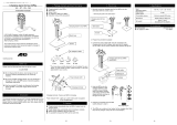
2.3.1 Electrical connections
Fig. 1: Electrical connection of an alarm signalling unit to a
switching amplifier (example)
A Hazardous area B Non-hazardous area
1 FAM3200 flowmeter with alarm signalling unit
2 NAMUR input switching amplifier 3 Switching amplifier
4 Switching amplifier output 5 Switching amplifier power supply
The circuits (between the alarm signalling units and the
switching amplifier) are intrinsically safe. The switching
amplifier itself must be mounted outside the hazardous area.
Change from two to one column
G11959
B
A
U
U
1
+
-
F
3
42
5

FAM3200 | CI/FAM3200-EN Rev. B 7
2.4 Limit value tables
Devices for use in category 1 (zone 0 in meter tube)
Equipment: T
medium
= T
ambient
≥ -20 °C (-4 °F)
Atmospheric conditions: 0.8 ... 1.1 bar (11.6 ... 15.95 psi)
Category 1 refers to the interior of the meter tube. Ensure that the ambient conditions are suitable for devices in zone 1 (e.g. by
ensuring sufficient ventilation).
Permissible ambient temperature T
ambient
40 °C (104 °F) 50 °C (122 °F) 60 °C (140 °F)
Electrical data Permissible measuring medium temperature T
medium
in the relevant temperature class [°C (°F)]
U
I
[V] I
I
[mA] P
I
[mW] C
I
[nF] L
I
[μH] T6 T5 T4 T6 T5 T4 T6 T5 T4
16 25 34 30 100 60
(140)
60
(140)
60
(140)
60
(140)
60
(140)
60
(140)
60
(140)
60
(140)
60
(140)
25 64 60
(140)
60
(140)
60
(140)
60
(140)
60
(140)
60
(140)
60
(140)
60
(140)
60
(140)
52 169 50
(122)
60
(140)
60
(140)
35
(95)
60
(140)
60
(140)
25
(77)
60
(140)
60
(140)
76 242 10
(50)
50
(122)
60
(140)
— 35
(95)
60
(140)
— 25
(877)
50
(122)
Devices for use in category 2 (zone 1)
Equipment: T
medium
= T
ambient
≥ -20 °C (-4 °F)
Permissible ambient temperature T
ambient
40 °C (104 °F) 50 °C (122 °F) 60 °C (140 °F)
Electrical data Permissible measuring medium temperature T
medium
in the relevant temperature class [°C (°F)]
U
I
[V] I
I
[mA] P
I
[mW] C
I
[nF] L
I
[μH] T6 T5 T4 T3 T6 T5 T4 T3 T6 T5 T4 T3
16 25 34 30 100 85
(185)
100
(212)
135
(275)
180
(356)
85
(185)
100
(212)
135
(275)
165
(329)
85
(185)
100
(212)
135
(275)
155
(311)
25 64 85
(185)
100
(212)
135
(275)
180
(356)
85
(185)
100
(212)
135
(275)
165
(329)
70
(158)
100
(212)
135
(275)
155
(311)
52 169 50
(122)
85
(185)
130
(266)
130
(266)
35
(95)
70
(158)
115
(239)
115
(239)
25
(77)
60
(140)
100
(212)
100
(212)
76 242 10
(50)
50
(122)
80
(176)
80
(176)
— 35
(95)
65
(149)
65
(149)
— 25
(77)
50
(122)
50
(122)
Change from one to tw o columns

8 CI/FAM3200-EN Rev. B | FAM3200
3 Functional description
The flowmeters in the FAM3200 work according to the float
principle.
The position of the float in the conical meter tube is
proportional to the flow.
A magnet in the float translates the height of the float as a
measurement for the flow to the decouple-proof magnet
follower system of the flowmeter.
The flow rate value is indicated on a scale by a pointer
mounted on a rotating shaft.
Fig. 2: Structure (example)
1 Meter housing 2 Meter tube 3 Float with magnet
4 Indicator housing 5 Magnet follower system 6 Cable entry
The devices are used for local indication of the current flow
rate with integrated alarm signalling units as flow rate monitors
or with differential pressure regulators.
The devices are also available with an angular position
transmitter with 4 ... 20 mA output signal as an option.
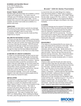
4 Product identification
4.1.1 Name plate
The name plate is located on the indicator housing.
Fig. 3: Name plate (example)
1 Type designation 2 Serial number 3 Order number
4 ATEX marking 5 Ambient temperature
6 Measuring medium temperature 7 Maximum flow rate
8 Details of measuring medium 9 Manufacturer's address
j CE mark
NOTE
The information on the permissible measuring medium
temperature (T
med
) can be found in chapter "Specifications"
on page 16.
G00744
1
2
3
4
5
6
G11966
Qmax= 32.000 m3/h (qn)
Nitrogen
685.000 kPa (a) 20.0 °C
Model: FAM3225
Order no.: 000000123/X001 /123456
Model no.: D10A32-25DAA5TTA0A0A1M1
Tüv 03 ATEX2151
II 1/2G c TX Ga/Gb
II 2D T115°C Db
Tamb = -40°C...+60°C
Tmed acc. to Manual
0044
ABB Automation Products GmbH
37079 Göttingen - Made in Germany -
1
2
3
4
5
6
7
8
9
j

FAM3200 | CI/FAM3200-EN Rev. B 9
4.1.2 Factory plate
In addition to the name plate, the factory plate is also on the
meter tube of the flowmeter.
Fig. 4: Factory plate
1 CE mark 2 Serial number of the sensor
3 Reason for exception under article 4, paragraph 3 of the Pressure
Equipment Directive
4 Measuring medium temperature
5 Manufacturer's address 6 Year of construction
7 Material of the pressure-bearing part (wetted part)
8Nominal diameter / nominal pressure rating
The reason for exception according to article 4 paragraph 3 of
the Pressure Equipment Directive is specified under PED.
The pressure equipment is classified in the SEP (= Sound
Engineering Practice) "Good Engineering Practice" category.
NOTE
The measuring medium temperature specified on the factory
plate only applies for the meter tube.
Depending on the device design (options, Ex approval), the
permissible measuring medium temperature may deviate
from the specified range.
The information on the permissible measuring medium
temperature (T
med
) can be found in chapter "Specifications"
on page 16.
5 Transport and storage
5.1 Inspection
Check the devices immediately after unpacking for possible
damage that may have occurred from improper transport.
Details of any damage that has occurred in transit must be
recorded on the transport documents.
All claims for damages must be submitted to the shipper
without delay and before installation.
5.2 Transport
— The center of gravity of some devices is not at the center
of the equipment.
— Use the any available attachment points on the device for
transport.
— Ensure that all transport locking devices are available and
correctly installed.
— Transport packaging marked visibly with the note "Caution
Glass".
5.3 Storage
Bear the following points in mind when storing devices:
— Store the device in its original packaging in a dry and
dust-free location.
— Observe the permitted ambient conditions for transport
and storage.
— Avoid storing the device in direct sunlight.
— In principle, the devices may be stored for an unlimited
period. However, the warranty conditions stipulated in the
order confirmation of the supplier apply.
The ambient conditions for the transport and storage of the
device correspond to the ambient conditions for operation of
the device.
Adhere to the device data sheet!
5.4 Returning devices
For the return of devices, follow the instructions in the chapter
"Returning devices" on page 15.
G11967
Ser.-No.: D10A32_5 / 123456
1/2"NPT / 100 bar
Material: 1.4571
Manufactured: 2015 PED: SEP
Tmed = -30°C...+100°C
ABB Automation Products GmbH
37079 Göttingen - Made in Germany -
1
2
3
4
5
6
7
8

10 CI/FAM3200-EN Rev. B | FAM3200
6 Installation
6.1 Safety instructions
WARNING
Risk of injury due to process conditions.
The process conditions, e.g. high pressures and
temperatures, toxic and aggressive measuring media, can
give rise to hazards when working on the device.
— Before working on the device, ensure that the process
conditions do not pose any safety risks.
— If necessary, wear suitable personal protective
equipment when working on the device.
— Depressurize and empty the device / piping, allow to
cool and purge if necessary.
6.2 Installation conditions
6.2.1 General
The following points are to be considered during installation:
— The armored variable area flowmeter is installed vertically
in piping. The measuring media must flow from bottom to
top.
— Keep the device as far as possible from pipe vibrations.
Fastening the piping is normally sufficient.
— Keep the device as far as possible from powerful magnetic
fields. Magnetic fields that are required for operating
reasons must not influence the measurement result.
— The piping should be the same size as the connection size
of the flowmeter.
— Inlet and outlet sections are not required. Valves and pipe
bends can be screwed on directly.
— Avoid pulsating flows and sudden pressure surges.
— Use slow opening valves.
— If the flowmeter is installed in a pipeline where
decommissioning is impossible or inexpedient, a bypass
line should be provided.
— For gaseous measurement media, the flowmeter should
be installed as close as possible to the pipe constrictions.
The nominal diameter of the piping at the outlet of the
flowmeter should be measured as small as possible.
— Shut-off and throttle valves should preferably be attached
to the outlet of the flowmeter.
— For liquid measuring media, the nominal size of the piping
should be dimensioned as large as possible (if
economically viable).
Fig. 5: Installation of the flowmeter
1 Shut-off valve in the inlet 2 Flowmeter
3 Shut-off valve in the outlet 4 Bypass line
6.2.2 Installation recommendations
Refer to VDI / VDE Directive 3513 sheet 3, Selection and
Installation Recommendations for Variable Area Flowmeters.
6.2.3 Pressure chambers and collecting tanks
If piston pumps or compressors are used for the transport of
the measuring media, a pulsating flow of the measurement
media must be expected.
In order to reduce the pulsating of the float, the installation of
pressure chambers or collecting tanks in the piping before the
flowmeter is recommended.
6.2.4 Sensor insulation
If the flowmeter needs to be insulated, only the meter tube
must be included in the pipe insulation. The indicator housing
must not be insulated.
This prevents the temperature in the device from rising beyond
permitted limits.
G10736
ABB
1
2
3
4

FAM3200 | CI/FAM3200-EN Rev. B 11
6.2.5 Heat tracing
Trace heating may be used under the following conditions:
— The heat tracing must be installed in a way that ensures
there is no temperature increase in the indicator housing.
— The maximum permitted temperature of the heat tracing
must not exceed the permitted measuring medium
temperature.
— When using electrical heat tracing, attention must be paid
to potential functional impairment by electromagnetic
fields.
6.3 Operating conditions
A variable area flowmeter is specified for a defined set of
operating conditions of the measuring medium. For liquids and
gases, these are pressure and temperature-related properties
(density and viscosity) under operating conditions.
For gases, in particular, this means operating at a specific
operating pressure and operating temperature. The specified
accuracy of the device always refers to the operating
conditions underlying the specification.
6.3.1 Pressure loss
The available operating pressure at the measuring point must
be higher than the pressure loss listed for the flowmeter in the
specifications.
It is important to also consider the pressure loss downstream
from the flowmeter due to losses in the piping and other
fittings.
For information on pressure loss, see chapter "Measuring
range table" on page 17.
6.3.2 Prevention of compression oscillations when
measuring gases
With low flow amounts and low operating pressure, so-called
compression oscillations of the float can occur.
If the maximum upstream pressure listed in the specifications
is not reached, the flowmeter can optionally be equipped with
a mechanical float damper.
Damping is available for the device types FAM3225 and
FAM3255 with a process connection size > 1/4".
To prevent self-generated compression oscillations, note the
following information from VDI / VDE 3513 Sheet 3:
— Select a flowmeter with the lowest possible pressure loss.
— Minimize the piping length between the flowmeter and the
closest up or downstream throttling location.
— Restrict the usual measuring range from the usual
10 … 100 % to 25 … 100 %.
— When setting the flow rate value, always start assuming
larger values.
— Increase the operating pressure and consider its effect on
the flow rate values due to the change in gas density at
the new operating conditions.
— Minimize non-throttled, free volumes upstream and
downstream of the device.
6.3.3 Pressure shocks
Especially when measuring gases, it is possible that pressure
or shock waves can occur when fast opening solenoid valves
are employed and the piping cross-sections are not throttled,
or if there are gas bubbles in liquids.
As a result of the sudden expansion of the gas in the piping,
the float is forcibly driven against the upper floatstop.
Under certain conditions, this can lead to destruction of the
device.
The mechanical float damping is not suitable for the
compensation of pressure shocks!

12 CI/FAM3200-EN Rev. B | FAM3200
6.3.4 Solids content in the measuring medium
Variable area flowmeters have only limited suitability for
measuring media containing solids.
Depending on the concentration, particle size and type of
solid, increased mechanical abrasion may occur, especially at
the critical measuring edge of the float.
In addition, solidified deposits on the float can change its
weight and shape.
These effects can lead to erroneous measurement results,
depending on the float type.
In general, the use of appropriate filters is recommended in
such applications.
For the flow measurement of measuring media containing
magnetic particles, we recommend the installation of a
magnetic separator upstream of the variable area flowmeter.
6.4 Installation
6.4.1 General information
The flowmeters in the FAM3200 series are intended for vertical
pipe mounting.
The following points must be observed during installation in
the piping:
— The measuring medium must flow from bottom to top.
— The piping may not exert any impermissible forces or
torques on the device. The device must be disconnected
from the power supply for installation.
— Only gaskets made from a material that is compatible with
the measuring medium and measuring medium
temperature may be used
— Gaskets must not extend into the flow area since possible
turbulence could influence device accuracy.
6.4.2 Flowmeter installation
Install the flowmeter centrally in the piping at the required
position using the correct threaded connections.
When tightening the process connections on the flowmeter,
use a spanner of the corresponding size to counter the force.
Model Meter size Wrench size [mm]
FAM3220 / FAM3250 1/4" SW 22
FAM3225 / FAM3255 1/4" SW 19
3/8" SW 24
1/2" SW 27
1" SW 50
Check the process connections for tightness.
6.5 Electrical connections
6.5.1 Analog indicator with alarm signaling unit
NOTE
When using the device in potentially explosive atmospheres,
observe the connection data in chapter "Use in potentially
explosive atmospheres" on page 6!
Specifications
Operating mode bistable
Switching function NAMUR contact
Nominal voltage 8 V DC (Ri approx. 1 kΩ)
Operating voltage 5 ... 25 V DC
Switching frequency Maximum 5 kHz
Connection type Cable, 2-wire, brown (+) / blue (-),
length 1.75 m (5.74 ft)
1)
Switching point single alarm Minimum 0 … 60 %
Maximum 40 … 100 %
Switching point double alarm Minimum setting range approx. 5 %
Setting accuracy ±2 % of measured value
Reproducibility ±0.5 % of scale end value
1) Other cable lengths available on request.
Temperature and electrical data
The following table shows the maximum permitted measuring
medium temperature T
medium
and the permitted electrical data
depending on the ambient temperature T
ambient
and the
gasket material.
Ambient temperature T
ambient
40 °C (104 °F) 50 °C (122 °F) 60 °C (140 °F)
Electrical data T
medium
maximum [°C (°F)]
I
i
[mA] P
i
[mW]
A B A B A B
25 34 100
(212)
180
(356)
100
(212)
165
(329)
100
(212)
155
(311)
25 64 100
(212)
180
(356)
100
(212)
165
(329)
100
(212)
155
(311)
52 169 100
(212)
130
(266)
100
(212)
115
(239)
100
(212)
100
(212)
76 242 80
(176)
80
(176)
65
(149)
65
(149)
50
(122)
50
(122)
A
Gasket material Buna N
B
Gasket material Viton A / Kalrez

FAM3200 | CI/FAM3200-EN Rev. B 13
6.5.2 Switching amplifier
Additional switching amplifiers are needed to operate the
alarm signaling units.
See chapter "Switching amplifier" on page 13 and the
"Ordering information" section of the data sheet for further
information.
Specifications
Power supply 230 V AC, +10 % / -15 %, 45 … 60 Hz
115 V AC, +10 % / -15 %, 45 … 60 Hz
24 V DC, +10 % / -15 %
Output One or two switching relays with potential-free
changeover contacts
Switching capacity Maximum 250 V, maximum 4 A, maximum
500 VA
Maximum permissible
cable length
Between switch amplifier and alarm signaling
unit: 300 m (984 ft)
Permissible ambient
temperature range
-20 … 60 °C (-4 … 140 °F)
Electrical connection Screw terminals, maximum 2.5 mm
2
(14 AWG)
Type of assembly 35 mm top-hat rail in accordance with
EN 60715:2001
IP rating IP 20 in accordance with EN 60529
Weight Approx. 150 g (0.3 lb)
6.5.3 Analog indicator with transmitter
Specifications
Output signal 4 … 20 mA, two-wire technology
Power supply maximum 30 V DC
Power consumption Maximum 30 mA
Connection type Cable, 2-wire, brown (+) / blue (-), length
1.75 m (5.74 ft)
1)
Ambient temperature
range
-20 … 40 °C (-4 … 104 °F)
Version Angular position transmitter in two-wire
technology
1) Other cable lengths available on request.
7 Commissioning
CAUTION
Risk of burns due to hot measuring media.
The device surface temperature may exceed 70 °C (158 °F),
depending on the measuring medium temperature!
Before starting work on the device, make sure that it has
cooled sufficiently.
During commissioning of the flowmeter, observe the following
points:
— The ambient and operating conditions (pressure,
temperature, power supply) must correspond to the
details on the name plate and the specifications.
— Open the shut-off valves slowly in order to prevent
pressure surges that can damage the flowmeter.
— For liquid measurement media, vent the pipeline if
necessary.
— For devices with alarm signalling units, set these to the
required switching points.
7.1 Adjusting the alarm signalling unit
The alarm signalling unit is designed as a proximity switch.
When inserted in the proximity switch, the metal tag initiates
the switching process. The switching point can be adjusted
with a screwdriver.
Fig. 6: Single alarm (example)
1 Metal tag 2 Alarm signalling unit (proximity switch)
3 Alarm adjustment 4 Indicator
1. Unscrew the housing cover.
2. Adjust the alarm setting to the required switching point
using a flat-bladed screwdriver.
3. Screw on housing cover.
7.2 Operating instructions
If there is a chance that safe operation is no longer possible,
take the device out of operation and secure it against
unintended startup.
G00745
1
2
4
3

14 CI/FAM3200-EN Rev. B | FAM3200
8 Maintenance / Repair
WARNING
Risk of injury due to process conditions.
The process conditions, e.g. high pressures and
temperatures, toxic and aggressive measuring media, can
give rise to hazards when working on the device.
— Before working on the device, ensure that the process
conditions do not pose any safety risks.
— If necessary, wear suitable personal protective
equipment when working on the device.
— Depressurize and empty the device / piping, allow to
cool and purge if necessary.
CAUTION
Risk of burns due to hot measuring media.
The device surface temperature may exceed 70 °C (158 °F),
depending on the measuring medium temperature!
Before starting work on the device, make sure that it has
cooled sufficiently.
NOTE
Loss of CE conformity!
For pressure equipment consisting of assemblies, CE
conformity is only for devices in the factory-supplied state.
Components should only be replaced by the manufacturer's
service personnel or an authorized specialist workshop.
Replacing components yourself will render the CE conformity
invalid.
8.1 Spare parts
Repair and maintenance activities may only be performed by
authorized customer service personnel.
When replacing or repairing individual components, use
original spare parts.
NOTE
Spare parts can be ordered from ABB Service:
Please contact Customer Center Service acc. to page 2 for
nearest service location.
8.2 Cleaning
Soiling of the meter tube and the float will impair the
measuring accuracy of the device. The necessary cleaning
interval is dependent on the operating conditions and must be
set individually.
The meter tube and the float must be removed in order to
clean the device.
When cleaning the exterior of meters, make sure that the
cleaning agent used does not corrode the housing surface and
the seals.
To avoid static charge, a damp cloth must be used for
cleaning.
8.2.1 Disassembly of the meter tube
NOTE
Damage to the float!
Damage to the float due to incorrect disassembly.
Observe the following points when disassembling the meter
tube and the float!
— The float is precision made. During assembly/disassembly,
ensure that the guide ring and the measuring edge are not
damaged. A damaged float causes inaccuracies in the
measurement and can cause damage to the meter tube
under certain circumstances.
— Ensure that the meter tube is not exposed to impacts or
mechanical loads during disassembly.
Fig. 7: Disassembly of the meter tube
G11962
1
2
3
5
6
8
7
4
9
4
6
7
8
FAM3220
FAM3250
FAM3225
FAM3255

FAM3200 | CI/FAM3200-EN Rev. B 15
To disassemble the meter tube and the float for maintenance
purposes, proceed as follows:
FAM3220 / FAM3250
1. Loosen the threaded pin
1.
2. Remove the retaining ring
2.
3. Remove the pressure plate
3 and pressure piece 5.
4. Remove and clean the meter tube holder 6, meter
tube
7, and float 8.
5. Check the O-ring 4 for damage and replace if necessary.
Assembly is executed in the reverse sequence.
FAM3225 / FAM3255
1. Loosen the outlet fitting
9.
2. Remove and clean the meter tube holder
6, meter
tube 7, and float 8.
3. Check the O-ring
4 for damage and replace if necessary.
Assembly is executed in the reverse sequence.
8.3 Returning devices
Use the original packaging or a secure transport container of
an appropriate type if you need to return the device for repair
or recalibration purposes. Fill out the return form (see the
Appendix) and include this with the device.
According to the EU Directive governing hazardous materials,
the owner of hazardous waste is responsible for its disposal or
must observe the following regulations for shipping purposes:
All devices delivered to ABB must be free from any hazardous
materials (acids, alkalis, solvents, etc.).
Please contact Customer Center Service acc. to page 2 for
nearest service location.
9 Recycling and disposal
9.1 Dismounting
WARNING
Risk of injury due to process conditions.
The process conditions, e.g. high pressures and
temperatures, toxic and aggressive measuring media, can
give rise to hazards when dismantling the device.
— If necessary, wear suitable personal protective
equipment during disassembly.
— Before disassembly, ensure that the process conditions
do not pose any safety risks.
— Depressurize and empty the device / piping, allow to
cool and purge if necessary.
Bear the following points in mind when dismantling the device:
— Switch off the power supply.
— Disconnect electrical connections.
— Allow the device / piping to cool and depressurize and
empty. Collect any escaping medium and dispose of it in
accordance with environmental guidelines.
— Use appropriate tools to dismantle the device, taking the
weight of the device into consideration.
— If the device is to be used at another location, the device
should preferably be packaged in its original packing so
that it cannot be damaged.
— See the information in chapter "Returning devices" on
page 15.

16 CI/FAM3200-EN Rev. B | FAM3200
9.2 Disposal
This product and its packaging are manufactured from
materials that can be recycled by specialist recycling
companies.
Bear the following points in mind when disposing of them:
— This product is not subject to WEEE Directive 2012/19/EU
or relevant national laws (e.g. ElektroG in Germany).
— The product must be surrendered to a specialist recycling
company. Do not use municipal garbage collection points.
According to WEEE Directive 2012/19/EU, only products
used in private applications may be disposed of at
municipal garbage collection points.
— If it is not possible to dispose of old equipment properly,
ABB Service can take receipt of and dispose of returns for
a fee.
NOTE
Products that are marked with this symbol may
not be disposed of through municipal garbage
collection points.
10 Specifications
10.1 Material load
Fig. 8: PS: Pressure, TS: Temperature
Maximum permissible operating pressure
The permissible operating pressure is dependent on the
optional device equipment.
Model Option Max. permissible
operating pressure
FAM3225 /
FAM3255
Without 100 bar (1450.38 psi)
FAM3220 /
FAM3250
With needle valve 40 bar (580.15 psi)
With differential pressure
regulator
14 bar (203.05 psi)
(Standard, higher pressures
available on request)
Permissible measuring medium temperature
Permissible measuring medium temperature depending on
gasket material.
Gasket materials
O-ring / meter tube holder T
medium
min / max
Viton A / PVDF -20 ... 100 °C (-4 ... 212 °F)
Buna N / PVDF -30 ... 100 °C (-22 ... 212 °F)
Kalrez / PTFE -40 ... 180 °C (-40 ... 356 °F)
Viton A / PTFE -20 ... 180 °C (-4 ... 356 °F)
Buna N / PTFE -20 ... 100 °C (-4 ... 212 °F)
EPDM / PVDF -50 ... 100 °C (-58 ... 212 °F)
Viton / none -20 ... 180 °C (-4 ... 356 °F)
Buna N / none -30 ... 100 °C (-22 ... 212 °F)
Kalrez / none -40 ... 180 °C (-40 ... 356 °F)
NOTE
The permissible measuring medium temperature range is
dependent on which gasket material is used.
The details on the factory and name plate of the flowmeter
must be strictly observed.
Failure to comply with this information can result in
destruction of the gasket and the flowmeter.
Change from two to one column
G10735
0
20
(290)
40
(580)
60
(870)
80
(1160)
100
(1450)
120
(1740)
-60
(-76)
-30
(-22)
0
(32)
30
(86)
60
(140)
90
(194)
120
(248)
150
(302)
180
(356)
210
(410)
240
(464)
FAM3225 / FAM3255
FAM3220 / FAM3250
PS [bar (psi)]
TS [°C (°F)]

FAM3200 | CI/FAM3200-EN Rev. B 17
10.2 Measuring range table
10.2.1 Model FAM3220 / FAM3250 / FAM3225 / FAM3255, variable area and armored
The data listed applies to water at 20 °C (68 °F), 1 kg/dm
3
(62.43 lb/ft
3
),1 mPas (1 cP) and to air at 0 °C (32 °F), 1013 mbar
(14.7 psia). To set up devices for different measurement media or operating conditions please check the ABB Product Selection
Assistant, available at www.abb.com/flow.
Process
connection
1)
Maximum flowrate V
std
2)
[mPas (cp)]
P
dif
3)
[bar (psi)]
P
sta
4)
[bar (psi)]
D
p
5)
[mbar (psi)]
Order code
6)
Water
[l/h (USgal/h)]
Air
[m
3
/h (scfh)]
1/4" 1 (0.26) 35 (1.24) 4 (4) 0.7 (10.15) 1.0 (14.5) 8 (0.12) 01H
1.6 (0.42) 54 (1.91) 4 (4) 0.7 (10.15) 1.0 (14.5) 8 (0.12) 02H
2.5 (0.66) 100 (3.53) 6 (6) 0.7 (10.15) 1.0 (14.5) 8 (0.12) 03H
4 (1.06) 160 (5.65) 6 (6) 0.7 (10.15) 1.0 (14.5) 8 (0.12) 04H
6 (1.59) 230 (8.12) 18 (18) 0.7 (10.15) 1.0 (14.5) 8 (0.12) 05H
10 (2.64) 350 (12.36) 18 (18) 0.7 (10.15) 1.0 (14.5) 8 (0.12) 06H
16 (4.23) 540 (19.07) 18 (18) 0.7 (10.15) 1.0 (14.5) 8 (0.12) 07H
25 (6.6) 850 (30.02) 18 (18) 0.7 (10.15) 1.0 (14.5) 9 (0.13) 08H
40 (10.57) 1250 (44.14) 18 (18) 0.7 (10.15) 1.0 (14.5) 10.5 (0.15) 09H
60 (15.85) 1900 (67.1) 18 (18) 0.7 (10.15) 1.0 (14.5) 12.5 (0.18) 10H
100 (26.42) 3100 (109.48) 12 (12) —
7)
1.0 (14.5) 17.0 (0.25) 11H
1) Connection nominal size
2) V
std
: Maximum permissible viscosity without calibration.
3) P
dif
: Minimum required differential pressure for operation with a differential pressure regulator (FAM3220 / FAM3250 only).
4) P
sta
: Minimum required static pressure to prevent compression oscillations. For lower pressures, consult ABB.
5) Total pressure loss with stainless steel float at maximum flow.
6) Order code of the meter tube-float construction. See chapter Fehler! Verweisquelle konnte nicht gefunden werden. for further information.
7) Not available with differential pressure regulator.

18 CI/FAM3200-EN Rev. B | FAM3200
10.2.2 Model FAM3225 / FAM3255, conical float and orifice plate
The data listed applies to water at 20 °C (68 °F), 1 kg/dm
3
(62.43 lb/ft
3
),1 mPas (1 cP) and to air at 0 °C (32 °F), 1013 mbar
(14.7 psia). To set up devices for different measurement media or operating conditions please check the ABB Product Selection
Assistant, available at www.abb.com/flow.
Process
connection
1)
Maximum flowrate V
std
2)
[mPas (cp)]
P
dif
3)
[bar (psi)]
P
sta
4)
[bar (psi)]
D
p
5)
[mbar (psi)]
Order code
6)
Water
[l/h (USgal/h)]
Air
[m
3
/h (scfh)]
3/8" or 1/2"
100 (26.42) 3200 (113.01) 8 (8) 4.0 (58.02) 0.3 (4.35) 60 (0.87) 20H
160 (42.27) 5000 (176.57) 8 (8) 4.0 (58.02) 0.3 (4.35) 70 (1.02) 21H
200 (52.83) 6000 (211.89) 8 (8) 4.0 (58.02) 0.3 (4.35) 80 (1.16) 22H
250 (66.04) 8000 (282.52) 8 (8) 4.0 (58.02) 0.3 (4.35) 90 (1.31) 23H
300 79.25) 9000 (317.83) 8 (8) 4.0 (58.02) 0.3 (4.35) 160 (2.32) 24H
1/2"
400 (105.67) 12000 (423.78) 8 (8) 4.0 (58.02) 0.3 (4.35) 75 (1.09) 30H
500 (132.09) 15000 (529.72) 8 (8) 4.0 (58.02) 0.3 (4.35) 85 (1.23) 31H
600 (158.5) 18000 (635.66) 8 (8) 4.0 (58.02) 0.3 (4.35) 95 (1.38) 32H
700 (184.92) 21000 (5547.61) 8 (8) 4.0 (58.02) 0.3 (4.35) 105 (1.53) 33H
800 (211.34) 24000 (847.55) 8 (8) 4.0 (58.02) 0.3 (4.35) 130 (1.89) 34H
1"
800 (211.34) 23800 (840.49) 3 (3) 16 (232.06) 0.4 (5.8) 60 (0.87) 40H
1000 (264.17) 29700 (1048.85) 3 (3) 16 (232.06) 0.4 (5.8) 62 (0.9) 41H
1600 (422.68) 47600 (1680.98) 3 (3) 16 (232.06) 0.4 (5.8) 74 (1.07) 42H
2000 (528.34) 59500 (2101.22) 3 (3) 16 (232.06) 0.4 (5.8) 85 (1.23) 43H
2500 (660.43) 74400 (2627.41) 3 (3) 16 (232.06) 0.4 (5.8) 105 (1.52) 44H
3000 (792.52) 89300 (3153.6) 3 (3) 16 (232.06) 0.4 (5.8) 130 (1.89) 45H
1) Connection nominal size
2) V
std
: Maximum permissible viscosity without calibration.
3) P
sta
: Minimum required static pressure for preventing compression oscillations. At low pressure, the use of the float damper is required.
4) P
min
: Minimum required static pressure in the device when using the optional float damper (Wendel).
5) Total pressure loss with stainless steel float at maximum flow.
6) Order code of the meter tube-float construction. See chapter Fehler! Verweisquelle konnte nicht gefunden werden. for further information.
11 Additional documents
NOTE
All documentation, declarations of conformity, and certificates are available in ABB's download area.
www.abb.com/flow
Change from one to tw o columns
Trademarks
® Buna-N is a registered trademark of DuPont Dow Elastomers.
® Kalrez and Kalrez Spectrum
TM
are registered trademarks of DuPont
Performance Elastomers.
™ Viton is a DuPont de Nemours trademark
Change from two to one column

FAM3200 | CI/FAM3200-EN Rev. B 19
12 Appendix
12.1 Return form
Statement on the contamination of devices and components
Repair and / or maintenance work will only be performed on devices and components if a statement form has been completed
and submitted.
Otherwise, the device / component returned may be rejected. This statement form may only be completed and signed by
authorized specialist personnel employed by the operator.
Customer details:
Company:
Address:
Contact person: Telephone:
Fax: E-Mail:
Device details:
Typ: Serial no.:
Reason for the return/description of the defect:
Was this device used in conjunction with substances which pose a threat or risk to health?
Yes No
If yes, which type of contamination (please place an X next to the applicable items)?
Biological Corrosive / irritating Combustible (highly / extremely combustible)
Toxic Explosiv Other toxic substances
Radioactive
Which substances have come into contact with the device?
1.
2.
3.
We hereby state that the devices / components shipped have been cleaned and are free from any dangerous or poisonous
substances.
Town/city, date Signature and company stamp

Contact us
CI/FAM3200-EN Rev. B 07.2017
A
BB Limited
Measurement & Analytics
Howard Road, St. Neots
Cambridgeshire, PE19 8EU
UK
Tel: +44 (0)870 600 6122
Fax: +44 (0)1480 213 339
Mail: [email protected]
A
BB Inc.
Measurement & Analytics
125 E. County Line Road
Warminster, PA 18974
USA
Tel: +1 215 674 6000
Fax: +1 215 674 7183
A
BB Automation Products GmbH
Measurement & Analytics
Dransfelder Str. 2
37079 Goettingen
Germany
Tel: +49 551 905-0
Fax: +49 551 905-777
Mail: vertrieb.messtechnik-
www.abb.com/flow
Note
We reserve the right to make technical changes or
modify the contents of this document without prior
notice.
With regard to purchase orders, the agreed
particulars shall prevail. ABB does not accept any
responsibility whatsoever for potential errors or
possible lack of information in this document.
We reserve all rights in this document and in the
subject matter and illustrations contained therein.
A
ny reproduction, disclosure to third parties or
utilization of its contents – in whole or in parts – is
forbidden without prior written consent of ABB.
Copyright© 2017 ABB
A
ll rights reserved
3KXF111300R4401
Translation of the original instruction
/