Page is loading ...

Installation and Operation Manual
X-VA-1110-1140-eng
Part Number: 541B040AHG
March, 2008 Brooks
®
1110 and 1140 Series
5
Model 1140
Full-View Flowmeter
(Flange Connections)
Glass Tube Full-View
®
Flowmeters
Model 1110
Full-View Flowmeter
(NPT Connections)

Installation and Operation Manual
X-VA-1110-1140-eng
Part Number: 541B040AHG
March, 2008
Brooks
®
1110 and 1140 Series
GLASS TUBE
EXPLOSION
HAZARD
WARNING
Plastic protective sleeve must remain over glass
tube. (Meter sizes 7 -13 only)
Fasten meter windows securely.
Do not operate above pressure and temperature
limits.
Avoid pressure and flow surges.
Do not service or repair while pressurized.
Read and understand instruction manual.
Failure to comply could result in serious personal
injury or property damage.
Protectivesleeve
must
remain
over
glass
tube.
(Meter sizes 7 - 13 only)
Fasten meter windows securely.
Failure to comply could result in serious personal
injury or property damage.
WARNING
GLASS TUBE EXPLOSION HAZARD
Essential Instructions
Read this page before proceeding!
Brooks Instrument designs, manufactures and tests its products to meet many national and international standards. Because
these instruments are sophisticated technical products, you must properly install, use and maintain them to ensure they
continue to operate within their normal specifications. The following instructions must be adhered to and integrated into your
safety program when installing, using and maintaining Brooks Products.
• Read all instructions prior to installing, operating and servicing the product. If this instruction manual is not the correct
manual, please see back cover for local sales office contact information. Save this instruction manual for future reference.
• If you do not understand any of the instructions, contact your Brooks Instrument representative for clarification.
• Follow all warnings, cautions and instructions marked on and supplied with the product.
• Inform and educate your personnel in the proper installation, operation and maintenance of the product.
• Install your equipment as specified in the installation instructions of the appropriate instruction manual and per applicable
local and national codes. Connect all products to the proper electrical and pressure sources.
• To ensure proper performance, use qualified personnel to install, operate, update, program and maintain the product.
• When replacement parts are required, ensure that qualified people use replacement parts specified by Brooks Instrument.
Unauthorized parts and procedures can affect the product's performance and place the safe operation of your process at
risk. Look-alike substitutions may result in fire, electrical hazards or improper operation.
• Ensure that all equipment doors are closed and protective covers are in place, except when maintenance is being
performed by qualified persons, to prevent electrical shock and personal injury.
Pressure Equipment Directive (PED)
All pressure equipment with an internal pressure greater than 0.5 bar (g) and a size larger than 25mm or 1" (inch) falls under the
Pressure Equipment Directive (PED). The Directive is applicable within the European Economic Area (EU plus Norway, Iceland
and Liechtenstein). Pressure equipment can be traded freely within this area once the PED has been complied with.
• Section 1 of this manual contains important safety and operating instructions related to the PED directive.
• Meters described in this manual are in compliance with EN directive 97/23/EC module H Conformity Assessment.
• All Brooks Instrument Flowmeters fall under fluid group 1.
• Meters larger than 25mm or 1" (inch) are in compliance with category I, II, III of PED.
• Meters of 25mm or 1" (inch) or smaller are Sound Engineering Practice (SEP).

Installation and Operation Manual
X-VA-1110-1140-eng
Part Number: 541B040AHG
March, 2008 Brooks
®
1110 and 1140 Series
Dear Customer,
We appreciate this opportunity to service your flow measurement and control requirements with a Brooks
Instrument device. Every day, flow customers all over the world turn to Brooks Instrument for solutions to their
gas and liquid low-flow applications. Brooks provides an array of flow measurement and control products for
various industries from biopharmaceuticals, oil and gas, fuel cell research and chemicals, to medical devices,
analytical instrumentation, semiconductor manufacturing, and more.
The Brooks product you have just received is of the highest quality available, offering superior performance,
reliability and value to the user. It is designed with the ever changing process conditions, accuracy requirements
and hostile process environments in mind to provide you with a lifetime of dependable service.
We recommend that you read this manual in its entirety. Should you require any additional information concerning
Brooks products and services, please contact your local Brooks Sales and Service Office listed on the back cover
of this manual or visit www.BrooksInstrument.com
Yours sincerely,
Brooks Instrument

Installation and Operation Manual
X-VA-1110-1140-eng
Part Number: 541B040AHG
March, 2008
Brooks
®
1110 and 1140 Series
THIS PAGE WAS
INTENTIONALLY
LEFT BLANK

i
Installation and Operation Manual
X-VA-1110-1140-eng
Part Number: 541B040AHG
March, 2008 Brooks
®
1110 and 1140 Series
Contents
Paragraph Page
Number Number
Section 1 Introduction
1-1 Description .........................................................................................................................................1-1
1-2 Design Features.................................................................................................................................1-1
1-3 Specifications .....................................................................................................................................1-1
1-4 Optional Equipment (Mountings, Valves and Flow Controllers)..........................................................1-7
Section 2 Installation
2-1 General ..............................................................................................................................................2-1
2-2 Receipt of Equipment.........................................................................................................................2-1
2-3 Recommended Storage Practice .......................................................................................................2-1
2-4 Return Shipment ................................................................................................................................2-2
2-5 Transit Precautions ............................................................................................................................2-2
2-6 Removal form Storage .......................................................................................................................2-2
2-7 Installation of Meter ............................................................................................................................2-3
Section 3 Operation
3-1 General ..............................................................................................................................................3-1
3-2 Operational Check .............................................................................................................................3-1
3-3 Operating Instructions ........................................................................................................................3-1
Section 4 Maintenance and Cleaning
4-1 General ..............................................................................................................................................4-1
4-2 Disassembly and Reassembly ...........................................................................................................4-2
Section 5 Accessories
5-1 General ..............................................................................................................................................5-1
Warranty, Local Sales/Service Contact Information....................................................................... Back Cover

ii
Installation and Operation Manual
X-VA-1110-1140-eng
Part Number: 541B040AHG
March, 2008
Brooks
®
1110 and 1140 Series
Contents
Figures
Figure Page
Number Number
1-1 Dimensions 127mm & 250mm Full-View Flowmeters........................................................................1-6
1-3 Float Types.........................................................................................................................................1-7
2-1 Typical Bypass Installation .................................................................................................................2-3
3-1 Typical Bypass Installation .................................................................................................................3-2
5-1a Model 1110 Exploded Parts Drawing..................................................................................................5-2
5-1b Model 1110 Exploded Parts Drawing (Continued) ..............................................................................5-3
5-1c Model 1110 Exploded Parts Drawing (Continued) ..............................................................................5-4
Tables
Table Page
Number Number
1-1 Pressure Ratings and PED Category.................................................................................................1-3
1-2 Connections .......................................................................................................................................1-5
1-3 Capacities, 150mm Scale, Rib Guided Tube, Spherical Float ............................................................1-8
1-4 Capacities, 250mm Scale, Rib Guided Tube, Spherical Float ............................................................1-8
1-5 Capacities, 250mm Scale, Rib Guided Tube, Standard Float ............................................................1-9
1-6 Capacities, 127mm Scale, Rib Guided Tubes, Standard Float..........................................................1-10
1-7 Capacities, 250mm Scale, Plain tapered Tubes, Rod Guided Float.................................................. 1-11
5-1 Model 1110 Exploded Parts List .........................................................................................................5-1

1-1
Installation and Operation Manual
X-VA-1110-1140-eng
Part Number: 541B040AHG
March, 2008
Brooks
®
1110 and 1140 Series
Section 1 Introduction
1-1 Description
The Brooks
®
Full-View
®
glass tube meters are designed to offer a wide
variety of meter configurations to meet a broad range of metering
applications. The packing gland seal construction provides for long-term,
leak-free, and reliable flow measurement.
1-2 Design Features
• Wide choice of application-specific materials and connections
• Rugged dowel-pin, side-plate construction
• Precision-bore, plain or ribbed borosilicate glass metering tubes
• Reliable, externally-adjustable packing glands for ease of maintenance
• Flanged or NPT connections with horizontal or vertical inlet and outlet
orientation
• Connections rotatable 360° at 90° intervals
1-3 Specifications
Capacities and Pressure Drops
150mm scale, Rib Guided Tubes, Spherical Float: Refer to Table 1-3
250mm scale, Rib Guided Tubes, Spherical Float: Refer to Table 1-4
250mm scale, Rib Guided Tubes, Standard Float: Refer to Table 1-5
127mm scale, Rib Guided Tubes, Standard Float: Refer to Table 1-6
250mm scale, Plain Tapered Tubes, Rod Guided Float: Refer to Table 1-7

1-2
Installation and Operation Manual
X-VA-1110-1140-eng
Part Number: 541B040AHG
March, 2008
Brooks
®
1110 and 1140 Series
Section 1 Introduction
Accuracy
Standard Flow Accuracy (127, 150, 250mm Tubes): ±2% Full Scale
Optional Flow Accuracy (127, 150, 250mm Tubes): ±1% Full Scale
Repeatability
0.5% Full Scale
Pressure Ratings
Refer to Table 1-1 for maximum non-shock pressure for rib guided and
plain tapered tubes.
Pressure Equipment Directive (PED) 97/23/EC See Table 1-1.
Scales
Standard: Detachable aluminum plate.
Length: 127mm, 150mm and 250mm.
Graduations: Choice of direct reading units, millimeter or percentage of
maximum flow.
Ambient Temperature Limits
33°F to 125°F (1°C to 52°C).
Operating Fluid Temperature Limits
Maximum: 250°F (121°C) for metallic end fittings
Reduced ratings on meters with nonmetallic end fittings. Refer to Table 1-1.
Minimum: 33°F (1°C)
Materials of Construction:
Metering Tube
Borosilicate glass.
Protective Tube Sleeve, Size 7 (1/2") and larger
UV stabilized polycarbonate.
Floats (Figure 1-3)
Standard Sizes 2-7 (spherical): sapphire, tantalum, glass, Carboloy
®
, 316
stainless steel, Monel
®
(Size 7 only).
Standard Sizes 8-13: 316 stainless steel.
Optional Sizes 8-13: Hastelloy C
®
.
Float Stops
Standard, Sizes 2-8: 316 SS spring.
Optional, Sizes 2-8: Hastelloy C.
Standard, Sizes 9-13: Aluminum for brass & steel fittings, 316 SS for 316
stainless steel fittings.
Guide Rods and Cartridges
Standard: 316 stainless steel.
Optional: Hastelloy C.

1-3
Installation and Operation Manual
X-VA-1110-1140-eng
Part Number: 541B040AHG
March, 2008
Brooks
®
1110 and 1140 Series
Section 1 Introduction
End Maximum Operating Pressure (psig)
2
Meter Fitting @ 70°F @ 150°F
1
@ 250°F PED
Size Material (21°C) (66°C) (121°C) CAT.
2 CPVC 100 100 Not Available
Metal 500 500 500
6 CPVC 100 100 Not Available
Metal 450 450 450
7 CPVC 100 100 Not Available
Metal 350 350 350
SEP
8 CPVC 100 100 Not Available
Metal 300 300 300
9 PVC 100 100 (Note 1) Not Available
Metal 175 175 175
10 PVC 100 100 (Note 1) Not Available
Metal 100 100 100
12 Metal 75 75 75 SEE
NOTE
3
13 Metal 100 100 100
NOTES:
1
Maximum temperature rating for nonmetal end fittings is 150°F (66°C) for all
materials except PVC, which is 140°F.
2
Flanged unit pressure ratings are limited to ANSI flange ratings whichever is
lower.
3
Sizes 12 and 13 do not conform to Pressure Equipment Directive 97/23/EC,
therefore it cannot be sold or used in the EU/EFTA.
Table 1-1 Pressure Ratings and PED Category
GLASS TUBE
EXPLOSION
HAZARD
WARNING
Plastic protective sleeve must remain over glass
tube. (Meter sizes 7 -13 only)
Fasten meter windows securely.
Do not operate above pressure and temperature
limits.
Avoid pressure and flow surges.
Do not service or repair while pressurized.
Read and understand instruction manual.
Failure to comply could result in serious personal
injury or property damage.

1-4
Installation and Operation Manual
X-VA-1110-1140-eng
Part Number: 541B040AHG
March, 2008
Brooks
®
1110 and 1140 Series
Section 1 Introduction
Housing and Window Bezel
Standard: Aluminum with polyurethane paint.
Optional: 18-8 stainless steel.
End Fittings
316 stainless steel,steel, Hastelloy C, CPVC Sizes 2-8,
PVC Sizes 9-10, brass.
(Brass, Hastelloy C, CPVC/PVC fittings not available with flanged
connection).
Window
Scratch resistant, UV stabilized polycarbonate.
Protectivesleeve
must
remain
over
glass
tube.
(Meter sizes 7 - 13 only)
Fasten meter windows securely.
Failure to comply could result in serious personal
injury or property damage.
WARNING
GLASS TUBE EXPLOSION HAZARD
Packing Material
Standard: Teflon
®
, Neoprene
®
, Viton
®
fluoroelastomers.
O-rings
Standard: Teflon.
Optional: Buna, Viton
®
fluoroelastomers.
Gland Rings
Standard: Steel, 18-8 stainless steel.
Gland Followers
Standard: Sizes 2-9 aluminum, Sizes 10-13 steel.
Optional: 18-8 stainless steel.
Side Plate Gaskets
Anchorite.
Bolts
18-8 stainless steel.
Connections (Refer to Table 1-2)
Standard:
150 lbs, 300 lbs RF flanges per ANSI B 16.5
NPT female connections.
Optional:
125/175 RA flange finish
Flat faced flanges.
Connection Orientation
Vertical or horizontal optional on inlets and outlets.
Connection rotatable 360° at 90° intervals.
Meter Dimensions
127mm to 250mm (Refer to Figure 1-1)

1-5
Installation and Operation Manual
X-VA-1110-1140-eng
Part Number: 541B040AHG
March, 2008
Brooks
®
1110 and 1140 Series
Section 1 Introduction
Model 1110 Model 1114 Model 1140 Model 1144
Meter Inlet&Outlet Inlet&Outlet Inlet&Outlet Inlet&Outlet
Size Horizontal Vertical Horizontal Vertical
(NPT) (NPT) (Flange) (Flange)
2 to 6 1/4" 1/4" 1/2" 1/2"
7 and 8 1/2" 1/2" 1/2" 1/2"
9 3/4" 3/4" 1" 1"
10 3/4" 1" 1" 1"
12 1-1/2" 1-1/2" 1-1/2" 1-1/2"
13 1-1/2" 2" 2" 2"
Table 1-2 Connections

1-6
Installation and Operation Manual
X-VA-1110-1140-eng
Part Number: 541B040AHG
March, 2008
Brooks
®
1110 and 1140 Series
Section 1 Introduction
All Dimensions in Inches
1110 - 1140 1114 1144
Nominal Scale Length (MM)
Nominal
Scale Length
(MM)
Nominal
Scale Length
(MM)
127 250 127 250 127 250
ABABAAAA D E
2-6* 10.12 8.59 15.12 13.59 9.63 14.63 14.88 19.88 2.38 3.5
7&8 15.38 11.5 20.38 16.5 12 17 17.88 22.88 3.25 3.5
9 17 12.5 22 17.5 12.25 17.25 17.75 22.75 3.75 4
10 17.88 12.5 22.88 17.5 12.25 17.25 17.5 22.5 4.44 4
12 20.12 15.5 25.12 20.5 15.88 20.88 21.38 26.38 4.38 5
13 21.25 15.5 26.25 20.5 15.12 20.12 20.63 25.63 4.88 5
* Also available in 150mm scale length. Dimensions are identical to 127mm scale length
Flange dimensions apply to 150# & 300# raised face or flat face flanges
All Dimension in Millimeters
1110 - 1140 1114 1144
Nominal Scale Length (MM)
Nominal
Scale Length
(MM)
Nominal
Scale Length
(MM)
127 250 127 250 127 250
ABABAAAA D E
2-6* 257.0 218.2 384.0 345.2 244.6 371.6 378.0 505.0 60.5 88.9
7&8 390.7 292.1 517.7 419.1 304.8 431.8 454.2 581.2 82.6 88.9
9 431.8 317.5 558.8 444.5 311.2 438.2 450.9 577.9 95.3 101.6
10 454.2 317.5 581.2 444.5 311.2 438.2 444.5 571.5 112.8 101.6
12 511.0 393.7 638.0 520.7 403.4 530.4 543.1 670.1 111.3 127.0
13 539.8 393.7 666.8 520.7 384.0 511.0 524.0 651.0 124.0 127.0
* Also available in 150mm scale length. Dimensions are identical to 127mm scale length
Flange dimensions apply to 150# & 300# raised face or flat face flanges
Meter
Size
All
Meters
All
Meters
Meter
Size
All
Meters
All
Meters
Figure 1-2 Dimensions 127mm and 250mm Full-View Flowmeters

1-7
Installation and Operation Manual
X-VA-1110-1140-eng
Part Number: 541B040AHG
March, 2008
Brooks
®
1110 and 1140 Series
Section 1 Introduction
1-4 Optional Equipment ( Mountings, Valves and Flow Controllers)
• Mountings: Brackets for panel mounting flush or front of panel
• Valves: Available for connection sizes 1/4” through 1” only. Horizontal
stem in outlet or inlet and fitting Sizes 2 through 10.
• Flow Controller: Brass or 316 Stainless steel integrally piped to Sizes
2-6. See Brooks publication DS-FCA.
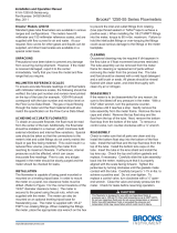
Figure 1-3 Float Types
Spherical - Lowest meter
capacity and no viscous fluids
with medium capacity.
Type RV (rib guided) -
Highest immunity to viscous
fluids with medium meter
capacity. (Most stable)
Type GV (rod guided) -
Analogous in design to a
sharp edge orifice. Gives
most immunity to viscosity
variations of the fluid being
metered.
Type LJ - Maximum flowme-
ter capacity with limited vis-
cosity immunity.
Type RS (rib guided) - High
flow capacity with some
immunity to viscous fluids.
Type GS (rod guided) -
ANalogous in design to a flow
nozzle or venturi. Offers the
maximum flow capacity in any
given size flowmeter.
Type RV
(Rib guided)
Type RS
(Rib guided)
Type LJ
Spherical
READ
HERE
READ
HERE
READ
HERE
READ
HERE

1-8
Installation and Operation Manual
X-VA-1110-1140-eng
Part Number: 541B040AHG
March, 2008
Brooks
®
1110 and 1140 Series
Section 1 Introduction
Table 1-4 Capacities,
250mm Scale, Rib Guided Tube, Spherical Float
Maximum Flow Rate
Meter Water Air @ 14.7 psia
Size Tube Float (cc/min.) and 70°F (21°C)
Glass 5.5 366 sccm
Sapphire 10.1 500 sccm
R-2-25-D Stn. Steel 19.8 810 sccm
Carboloy 32.2 1,200 sccm
Tantalum 34.8 1,280 sccm
Glass 16.8 0.84 slpm
Sapphire 26.8 1.11 slpm
R-2-25-A Stn. Steel 46.5 1.70 slpm
Carboloy 71.5 2.46 slpm
Tantalum 77.0 2.62 slpm
Glass 49.0 2.20 slpm
Sapphire 74.5 2.86 slpm
2 R-2-25-B Stn. Steel 124 4.3 slpm
Carboloy 186 6.2 slpm
Tantalum 198 6.6 slpm
Glass 82 3.78 slpm
Sapphire 125 4.95 slpm
R-2-25-C Stn. Steel 212 7.45 slpm
Carboloy 318 10.3 slpm
Tantalum 342 10.9 slpm
Glass 196 8.6 slpm
Sapphire 292 11.0 slpm
R-6-25-A Stn. Steel 485 16.2 slpm
Carboloy 715 22.8 slpm
Tantalum 760 24.2 slpm
Glass 550 22.8 slpm
Sapphire 810 29.0 slpm
R-6-25-B Stn. Steel 1,300 42.0 slpm
Carboloy 1,860 58.5 slpm
6 Tantalum 1,980 62.0 slpm
Glass 275 12.3 slpm
Sapphire 412 15.6 slpm
R-6M-25-1 Stn. Steel 676 22.8 slpm
Tantalum 1,087 33.9 slpm
Glass 605 24.2 slpm
7 R-7M-25-1 Stn. Steel 1,286 42.7 slpm
Monel 1,360 44.8 slpm
MAXIMUM FLOW RATE
METER WATER AIR @ 14.7 PSIA
SIZE TUBE FLOAT (CC/MIN.) AND 70°F (21°C)
GLASS * 0.524 47.1 SCC/MIN
SAPPHIRE 1.02 73.3 SCC/MIN
R-2-15-AAA STN. STL. 2.42 140.0 SCC/MIN
SEE NOTE CARBOLOY 4.77 238.0 SCC/MIN
BELOW * TANTALUM 5.31 260.0 SCC/MIN
GLASS 0.96 83.8 SCC/MIN
SAPPHIRE 1.86 128.0 SCC/MIN
R-2-15-AA STN. STL. 4.34 245.0 SCC/MIN
CARBOLOY 8.37 416.0 SCC/MIN
TANTALUM 9.30 454.0 SCC/MIN
GLASS 5.58 361.0 SCC/MIN
SAPPHIRE 10.20 491.0 SCC/MIN
2 R-2-15-D STN. STL. 19.80 790.0 SCC/MIN
CARBOLOY 31.90 1170.0 SCC/MIN
TANTALUM 34.40 1250.0 SCC/MIN
GLASS 16.1 0.8 SLPM
SAPPHIRE 25.2 1.0 SLPM
R-2-15-A STN. STL. 44.2 1.6 SLPM
CARBOLOY 67.7 2.3 SLPM
TA NTAL UM 72.5 2.5 SL PM
GLASS 50.6 2.3 SLPM
SAPPHIRE 76.2 2.9 SLPM
R-2-15-B STN. STL. 127 4.4 SLPM
CARBOLOY 189 6.4 SLPM
TA NTAL UM 202 6.7 SL PM
GLASS 81.1 3.7 SLPM
SAPPHIRE 123 4.8 SLPM
R-2-15-C STN. STL. 208 7.2 SLPM
CARBOLOY 312 10.1 SLPM
TANTALUM 333 10.6 SLPM
GLASS 191 8.3 SLPM
SAPPHIRE 284 10.6 SLPM
R-6-15-A STN. STL. 468 15.7 SLPM
CARBOLOY 690 22.0 SLPM
6 TANTALUM 735 23.3 SLPM
GLASS 548 22.6 SLPM
SAPPHIRE 809 28.6 SLPM
R-6-15-B STN. STL. 1290 41.6 SLPM
CARBOLOY 1850 58.1 SLPM
TANTALUM 1960 61.4 SLPM
* R-2-15-AAA TUBE WITH GLASS FLOAT NOT AVAILABLE WITH
1% ACCURACY.
Table 1-3 Capacities,
150mm Scale, Rib Guided Tube, Spherical Float

1-9
Installation and Operation Manual
X-VA-1110-1140-eng
Part Number: 541B040AHG
March, 2008
Brooks
®
1110 and 1140 Series
Section 1 Introduction
1
Viscosity immunity ceiling listed is for stainless steel float and fluid specific gravity 1.0.
2
Minimum operating downstream pressure for gas service (psig)
Table 1-5 Capacities, 250mm Scale , Rib Guided Tubes, Standard Float
Water Air @ 14.7 psia and 70°F (21°C)
Pressure Viscosity Pressure
Meter Drop Immunity Drop psi
Size Tube Float gpm lpm Inches W.C. Ceiling, CS
1
scfm slpm Inches W.C. Critical
2
8-RV-3 0.55 2.08 2.0 2.0 2.22 62.9 3.0 0
8-RV-8 0.78 2.95 5.0 3.3 3.22 91.2 6.0 0
8-RS-8 1.00 3.79 6.0 1.7 4.18 118.4 7.0 0
R-8M-25-2 8-RV-14 1.04 3.94 8.0 4.6 4.28 121.2 9.0 0
8-RS-14 1.32 5.00 11.0 1.8 5.48 155.2 12.0 0
8-RV-31 1.50 5.68 17.0 6.0 6.12 173.3 19.0 30
8-RS-31 1.89 7.15 22.0 2.6 7.76 219.8 25.0 30
8 8-LJ-48 3.01 11.39 45.0 1.0 13.01 368.4 51.0 30
8-RV-3 0.78 2.95 4.0 2.0 3.17 89.8 4.0 0
8-RV-8 1.09 4.13 7.0 3.7 4.45 126.0 8.0 0
8-RS-8 1.40 5.30 10.0 1.8 5.86 166.0 11.0 0
R-8M-25-4 8-RV-14 1.45 5.49 12.0 5.4 5.88 166.5 14.0 0
8-RS-14 1.83 6.93 17.0 1.9 7.56 214.1 19.0 0
8-RV-31 2.06 7.80 23.0 7.0 8.32 235.6 28.0 30
8-RS-31 2.59 9.80 33.0 3.1 10.66 301.9 37.0 30
8-LJ-48 4.88 18.47 93.0 1.0 20.32 575.5 106.0 30
9-RV-33 1.90 7.19 5.0 10.0 7.96 225.4 6.0 0
9-RS-33 2.52 9.54 6.0 2.3 10.46 296.2 7.0 0
R-9M-25-1 9-RV-87 3.08 11.66 12.0 15.0 12.56 355.7 14.0 30
9-RS-87 4.04 15.29 14.0 3.4 16.84 476.9 16.0 30
9-LJ-160 6.88 26.04 31.0 1.0 30.45 862.3 35.0 30
9 9-RV-33 2.53 9.58 6.0 11.0 10.45 295.0 7.0 0
9-RS-33 3.24 12.26 7.0 2.4 13.45 380.9 8.0 0
R-9M-25-3 9-RV-87 3.92 14.84 14.0 17.0 16.25 460.2 16.0 30
9-RS-87 5.12 19.38 17.0 3.5 21.20 600.4 20.0 30
9-LJ-160 9.65 36.53 43.0 1.0 44.18 1,251.2 49.0 30
10-RV-64 4.54 17.18 8.0 14.0 18.05 511.2 9.0 0
10-RS-64 5.64 21.35 10.0 3.0 23.65 669.8 12.0 0
R-10M-25-1 10-RV-138 6.42 24.30 17.0 22.0 26.60 753.3 19.0 30
10-RS-138 8.02 30.36 21.0 5.0 34.60 979.9 23.0 30
10-LJ-238 14.91 56.43 52.0 1.0 66.00 1,869.1 59.0 30
10 10-RV-64 6.28 23.77 11.0 15.0 25.76 729.5 13.0 0
10-RS-64 7.84 29.67 15.0 3.7 32.15 910.5 17.0 0
R-10M-25-3 10-RV-138 8.84 33.46 23.0 23.0 36.10 1,022.4 26.0 30
10-RS-138 10.93 41.37 29.0 5.5 45.90 1,299.9 33.0 30
10-LJ-238 23.10 87.43 98.0 1.0 105.70 2,993.4 112.0 30
12-RV-221 9.33 35.31 8.0 28.0 37.81 1,070.8 9.0 0
12-RV-343 11.71 44.32 12.0 35.0 47.12 1,334.4 14.0 30
R-12M-25-4 12-RS-221 12.46 47.16 9.0 4.0 50.65 1,434.4 10.0 0
12-RS-343 15.43 58.40 13.0 4.3 62.75 1,777.1 15.0 30
12-LJ-740 30.00 113.55 31.0 1.0 123.30 3,491.9 36.0 30
12 12-RV-221 17.21 65.14 10.0 29.0 70.80 2,005.1 11.0 0
12-RV-343 20.95 79.30 15.0 36.0 86.45 2,448.3 17.0 30
R-12M-25-5 12-RS-221 22.40 84.78 12.0 4.2 91.85 2,601.2 14.0 0
12-RS-343 26.90 101.82 18.0 4.5 112.00 3,171.8 20.0 30
12-LJ-740 67.60 255.87 65.0 1.0 299.50 8,481.8 75.0 30
13-RV-510 19.94 75.47 12.0 40.0 81.55 2,309.5 14.0 0
13-RV-760 23.79 90.05 18.0 50.0 96.00 2,718.7 20.0 30
R-13M-25-1 13-RS-510 26.89 101.78 15.0 7.3 108.00 3,058.6 17.0 0
13-RS-760 31.85 120.55 21.0 9.0 131.00 3,709.9 24.0 30
13-LJ-1394 54.60 206.66 46.0 1.0
13 13-RV-510 31.78 120.29 17.0 42.0 130.90 3,707.1 19.0 0
13-RV-760 37.60 142.32 24.0 52.0 155.20 4,395.3 27.0 30
R-13M-25-3 13-RS-510 42.52 160.94 23.0 7.6 176.60 5,001.3 26.0 0
13-RS-760 49.55 187.55 32.0 9.3 217.70 6,165.3 36.0 30
13-LJ-1394 98.60 373.20 92.0 1.0

1-10
Installation and Operation Manual
X-VA-1110-1140-eng
Part Number: 541B040AHG
March, 2008
Brooks
®
1110 and 1140 Series
Section 1 Introduction
1
Viscosity immunity ceiling listed is for stainless steel float and fluid specific gravity 1.0.
2
Minimum operating downstream pressure for gas service (psig)
Table 1-6 Capacities, 127mm Scale, Rib Guided Tubes, Standard Float
Water Air @ 14.7 psia and 70°F (21°C)
Pressure Viscosity Pressure
Meter Drop Immunity Drop psi
Size Tube Float gpm lpm Inches W.C. Ceiling, CS
1
scfm slpm Inches W.C. Critical
2
8-RV-3 0.50 1.89 2.0 2.0 2.05 58.1 2.0 0
8-RV-8 0.74 2.80 3.0 3.3 3.01 85.2 4.0 0
8-RS-8 0.92 3.48 4.0 1.7 3.84 108.7 4.0 0
R-8M-127-1 8-RV-14 0.96 3.63 6.0 4.6 3.95 111.9 6.0 0
8-RS-14 1.22 4.62 6.0 1.8 5.03 142.4 7.0 0
8-RV-31 1.38 5.22 11.0 6.0 5.60 158.6 13.0 30
8-RS-31 1.70 6.43 13.0 2.6 6.98 197.7 15.0 30
8 8-LJ-48 2.59 9.80 22.0 1.0 10.93 309.5 15.0 30
8-RV-3 0.72 2.73 2.0 2.0 2.94 83.3 2.0 0
8-RV-8 1.02 3.86 4.0 3.7 4.19 118.7 5.0 0
8-RS-8 1.30 4.92 5.0 1.8 5.40 152.9 6.0 0
R-8M-127-4 8-RV-14 1.34 5.07 7.0 5.4 5.46 154.6 8.0 0
8-RS-14 1.69 6.40 8.0 1.9 6.98 197.7 10.0 0
8-RV-31 1.85 7.00 14.0 7.0 7.53 213.2 15.0 30
8-RS-31 2.30 8.71 16.0 3.1 9.45 267.6 18.0 30
8-LJ-48 4.40 16.65 35.0 1.0 18.10 512.6 40.0 30
9-RV-33 1.70 6.43 4.6 10.0 7.00 198.2 6.0 0
9-RS-33 2.20 8.33 5.3 2.3 9.05 256.3 6.0 0
R-9M-127-1 9-RV-87 2.64 9.99 11.5 15.0 11.08 313.8 13.0 30
9-RS-87 3.46 13.10 13.0 3.4 14.40 407.8 15.0 30
9-LJ-160 5.91 22.37 26.6 1.0 26.03 737.2 31.0 30
9 9-RV-33 3.90 14.76 8.4 11.0 15.75 446.0 10.0 0
9-RS-33 4.90 18.55 10.8 2.4 20.35 576.3 13.0 0
R-9M-127-3 9-RV-87 5.55 21.01 18.1 17.0 23.30 659.9 21.0 30
9-RS-87 6.75 25.55 21.7 3.5 28.75 814.2 25.0 30
9-LJ-160 17.20 65.10 79.0 1.0 83.40 2,361.9 90.0 30
10-RV-64 4.28 16.20 7.0 14.0 17.90 506.9 8.0 0
10-RS-64 5.40 20.44 8.4 3.0 22.85 647.1 10.0 0
R-10M-127-1 10-RV-138 5.93 22.45 14.0 22.0 25.30 716.5 16.0 30
10-RS-138 7.41 28.05 16.2 5.0 31.50 892.1 19.0 30
10-LJ-238 13.65 51.67 36.0 1.0 57.90 1,639.7 41.0 30
10 10-RV-64 6.02 22.79 9.2 15.0 24.33 689.0 11.0 0
10-RS-64 7.56 28.61 11.4 3.7 30.80 872.3 13.0 0
R-10M-127-3 10-RV-138 8.01 30.32 17.2 23.0 33.45 947.3 20.0 30
10-RS-138 9.94 37.62 21.0 5.5 41.63 1,179.0 24.0 30
10-LJ-238 22.47 85.05 61.0 1.0 109.30 3,095.4 70.0 30
12-RV-221 8.60 32.55 8.0 28.0 35.23 997.7 9.0 0
12-RV-343 10.74 40.65 12.0 35.0 43.55 1,233.3 14.0 30
R-12M-127-1 12-RS-221 11.49 43.49 8.0 4.0 47.10 1,333.9 10.0 0
12-RS-343 13.97 52.88 13.0 4.3 59.70 1,605.7 15.0 30
12-LJ-740 24.30 91.98 28.0 1.0 99.80 2,826.3 32.0 30
12 12-RV-221 16.61 62.87 10.0 29.0 67.65 1,915.8 11.0 0
12-RV-343 19.68 74.49 14.0 36.0 80.30 2,274.1 17.0 30
R-12M-127-3 12-RS-221 21.83 82.63 12.0 4.2 89.70 2,540.3 13.0 0
12-RS-343 24.72 93.57 16.0 4.5 101.80 2,883.0 19.0 30
12-LJ-740 72.00 272.52 57.0 1.0
13-RV-510 19.28 72.97 12.0 40.0 78.25 2,216.0 14.0 0
13-RV-760 22.90 86.68 17.0 50.0 92.80 2,628.1 20.0 30
R-13M-127-1 13-RS-510 26.35 99.73 14.0 7.3 105.30 2,982.1 16.0 0
13-RS-760 31.30 118.47 20.0 9.0 126.10 3,571.2 23.0 30
13-LJ-1394 47.45 179.60 38.0 1.0
13 13-RV-510 30.40 115.06 16.0 42.0 125.00 3,540.0 18.0 0
13-RV-760 34.90 132.10 22.0 52.0 144.20 4,083.7 25.0 30
R-13M-127-3 13-RS-510 41.30 156.32 20.0 7.6 175.25 4,963.1 23.0 0
13-RS-760 46.50 176.00 27.0 9.3 199.80 5,658.3 31.0 30
13-LJ-1394 93.80 355.03 70.0 1.0

1-11
Installation and Operation Manual
X-VA-1110-1140-eng
Part Number: 541B040AHG
March, 2008
Brooks
®
1110 and 1140 Series
Section 1 Introduction
1
Viscosity immunity ceiling listed is for stainless steel float and fluid specific gravity 1.0.
2
Minimum operating downstream pressure for gas service (psig).
3
Float does not provide 10:1 flow range. Range will be 5:1 or better.
Table 1-7 Capacities, 250mm Scale, Plain Tapered Tubes, Rod Guided Float
Water Air @ 14.7 psia and 70°F (21°C)
Pressure Viscosity Pressure
Meter Drop Immunity Drop psi
Size Tube Float gpm lpm Inches W.C. Ceiling, CS
1
scfm slpm Inches W.C. Critical
2
8-GV-7 1.18 4.47 11.0 4.7 4.82 136.5 12.0 0
8-GS-7 1.54 5.83 17.0 1.6 6.50 184.1 19.0 0
8-GV-12 1.56 5.90 19.0 6.2 6.40 181.2 21.0 0
8-GS-12 2.06 7.80 31.0 1.6 8.60 243.6 35.0 0
8 8M-25-3 8-GV-26 2.24 8.48 39.0 9.1 9.23 261.4 45.0 30
8-GS-26 2.96 11.20 64.0 1.7 12.45 352.6 74.0 30
8-LG-27 3.84 14.53 106.0 1.0
8-LG-28 5.33 20.17 202.0 1.0
8-LG-37 6.40 24.22 293.0 1.0
9-GV-29 2.30 8.71 8.0 10.1 9.66 273.6 10.0 0
9-GS-29 3.23 12.23 13.0 1.8 13.53 383.2 15.0 0
9-GV-75 3.90 14.76 23.0 16.3 16.40 464.4 26.0 0
9 9M-25-2 9-GS-75 5.22 19.76 34.0 2.1 21.60 611.7 38.0 0
9-LG-60 7.02 26.57 52.0 1.0
9-LG-88 8.91 33.72 81.0 1.0
9-LG-124 11.00 41.64 121.0 1.0
10-GV-54 5.60 21.20 22.0 13.0 23.52 666.1 25.0 0
10-GS-54 7.84 29.67 48.0 1.7 33.12 938.0 55.0 0
10-GV-119 8.52 32.25 38.0 19.4 35.48 1,004.8 43.0 30
10 10M-25-2 10-GS-119 11.71 44.32 81.0 2.0 49.75 1,408.9 93.0 30
10-LG-191 16.00 60.56 146.0 1.0
10-LG-113 19.14 72.44 194.0 1.0
10-LG-164 25.20 95.38 327.0 1.0
10-LG-194 31.39 118.81 493.0 1.0
12-GV-201 11.44 43.30 15.0 26.7 48.00 1,359.4 17.0 0
12-GV-315 14.43 54.62 23.0 33.3 60.25 1,706.3 27.0 30
12-GS-201 16.06 60.79 23.0 4.0 66.35 1,879.0 27.0 0
12 12M-25-3 12-GS-315 20.05 75.89 35.0 5.0 82.70 2,342.1 41.0 30
12-LG-391 36.58 138.46 94.0 1.0
12-LG-490
3
43.90 166.16 131.0 1.0
12-LG-461 58.95 223.13 220.0 1.0
13-GV-465 23.66 89.55 28.0 40.0 100.00 2,832.0 32.0 0
13-GV-696 29.60 112.04 43.0 48.8 122.20 3,460.7 49.0 30
13-GS-465 33.31 126.08 47.0 6.0 139.00 3,936.5 53.0 0
13-GS-696 41.50 157.08 71.0 7.3 117.10 5,015.5 81.0 30
13 13M-25-2 13-LG-822 64.40 243.75 151.0 1.0
13-LG-844 69.20 261.92 172.0 1.0
13-LG-866
3
85.60 324.00 252.0 1.0
13-LG-950
3
102.6 388.34 352.0 1.0
13-LG-1402 118.0 446.63 464.0 1.0
13-LG-1465 129.5 490.16 551.0 1.0

1-12
Installation and Operation Manual
X-VA-1110-1140-eng
Part Number: 541B040AHG
March, 2008
Brooks
®
1110 and 1140 Series
Section 1 Introduction
THIS PAGE WAS
INTENTIONALLY
LEFT BLANK

2-1
Installation and Operation Manual
X-VA-1110-1140-eng
Part Number: 541B040AHG
March, 2008
Brooks
®
1110 and 1140 Series
Section 2 Installation
2-1 General
This section contains the procedures for the receipt and installation of the
instrument. Do not attempt to start the system until the instrument has
been permanently installed. It is extremely important that the start-up
procedures be followed in the exact sequence presented.
2-2 Receipt of Equipment
When the instrument is received, the outside packing case should be
checked for damage incurred during shipment. If the packing case is
damaged, the local carrier should be notified at once regarding his liability.
A report should be submitted to your nearest Product Service Department.
Brooks Instrument
407 W. Vine Street
P.O. Box 903
Hatfield, PA 19440 USA
Toll Free (888) 554-FLOW (3569)
Tel (215) 362-3700
Fax (215) 362-3745
E-mail: BrooksAm@EmersonProcess.com
www.BrooksInstrument.com
Brooks Instrument Brooks Instrument
Neonstraat 3 1-4-4 Kitasuna Koto-Ku
6718 WX Ede, Netherlands Tokyo, 136-0073 Japan
P.O. Box 428 Tel 011-81-3-5633-7100
6710 BK Ede, Netherlands Fax 011-81-3-5633-7101
Tel 31-318-549-300 Email: [email protected]
Fax 31-318-549-309
E-mail: [email protected]
Remove the envelope containing the packing list. Carefully remove the
instrument from the packing case. Make sure spare parts are not
discarded with the packing materials. Inspect for damaged or missing
parts.
2-3 Recommended Storage Practice
If intermediate or long-term storage of equipment is required, it is
recommended that the equipment be stored in accordance with the
following:
a. Within the original shipping container.
b. Stored in a sheltered area, preferably a warm, dry, heated
warehouse.
c. Ambient temperature of 70° F (21° C) nominal, 109° F (43° C)
maximum,
45° F (7° C) minimum.
d. Relative humidity 45% nominal, 60% maximum, 25% minimum.
Upon removal from storage a visual inspection should be conducted
to verify the condition of equipment is "as received".

2-2
Installation and Operation Manual
X-VA-1110-1140-eng
Part Number: 541B040AHG
March, 2008
Brooks
®
1110 and 1140 Series
Section 2 Installation
2-4 Return Shipment
Prior to returning any instrument to the factory, contact your nearest
Brooks location for a Return Materials Authorization Number (RMA#). This
can be obtained from one of the following locations:
Brooks Instrument
407 W. Vine Street
P.O. Box 903
Hatfield, PA 19440 USA
Toll Free (888) 554-FLOW (3569)
Tel (215) 362-3700
Fax (215) 362-3745
E-mail: BrooksAm@EmersonProcess.com
www.BrooksInstrument.com
Brooks Instrument Brooks Instrument
Neonstraat 3 1-4-4 Kitasuna Koto-Ku
6718 WX Ede, Netherlands Tokyo, 136-0073 Japan
P.O. Box 428 Tel 011-81-3-5633-7100
6710 BK Ede, Netherlands Fax 011-81-3-5633-7101
Tel 31-318-549-300 Email: [email protected]
Fax 31-318-549-309
E-mail: [email protected]
All flow instruments returned to Brooks requires completion of Form
RPR003-1, Brooks Instrument Decontamination Statement, along with a
Material Safety Data Sheet (MSDS) for the fluid(s) used in the instrument.
Failure to provide this information will delay processing by Brooks
personnel. Copies of these forms can be downloaded from the Brooks
website www.BrooksInstrument.com or are available from any Brooks
Instrument location listed above.
2-5 Transit Precautions
To safeguard against damage during transit, transport the instrument to
the installation site in the same container used for transportation from the
factory if circumstances permit.
2-6 Removal from Storage
Upon removal of the instrument from storage, a visual inspection should
be conducted to verify its "as-received" condition.
/