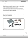
NavLinkz RL2-GVIF-B is a video inserter for front- and rear-view camera input and additional video source. It is compatible with Chevrolet Camaro (2013-2014), Lexus LS/GS/RX/ES/IS, Toyota Landcruiser, Prius and others (2007+), Jaguar XF X250, XK X150 (2007-2011), Land Rover Range Rover (Vogue) L322 (2005-2009). It has automatic switching to rear view camera by engagement of reverse gear, manual switching to front camera by keypad or factory button, activatable parking guide lines for rear-view camera, video-in-motion for connected video sources, and AV-inputs that are PAL/NTSC compatible.
NavLinkz RL2-GVIF-B is a video inserter for front- and rear-view camera input and additional video source. It is compatible with Chevrolet Camaro (2013-2014), Lexus LS/GS/RX/ES/IS, Toyota Landcruiser, Prius and others (2007+), Jaguar XF X250, XK X150 (2007-2011), Land Rover Range Rover (Vogue) L322 (2005-2009). It has automatic switching to rear view camera by engagement of reverse gear, manual switching to front camera by keypad or factory button, activatable parking guide lines for rear-view camera, video-in-motion for connected video sources, and AV-inputs that are PAL/NTSC compatible.


-
 1
1
-
 2
2
-
 3
3
-
 4
4
-
 5
5
-
 6
6
-
 7
7
-
 8
8
-
 9
9
-
 10
10
-
 11
11
-
 12
12
-
 13
13
-
 14
14
-
 15
15
-
 16
16


NavLinkz RL2-GVIF-B Installation guide
- Type
- Installation guide
- This manual is also suitable for
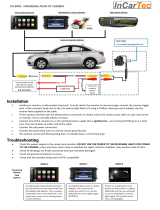
NavLinkz RL2-GVIF-B is a video inserter for front- and rear-view camera input and additional video source. It is compatible with Chevrolet Camaro (2013-2014), Lexus LS/GS/RX/ES/IS, Toyota Landcruiser, Prius and others (2007+), Jaguar XF X250, XK X150 (2007-2011), Land Rover Range Rover (Vogue) L322 (2005-2009). It has automatic switching to rear view camera by engagement of reverse gear, manual switching to front camera by keypad or factory button, activatable parking guide lines for rear-view camera, video-in-motion for connected video sources, and AV-inputs that are PAL/NTSC compatible.
Ask a question and I''ll find the answer in the document
Finding information in a document is now easier with AI
Related papers
-
NavLinkz RL2-DVD900 Installation guide
-
-
-
-
-
-
-
-
-
NavLinkz VL2-LR14-OPS Installation guide
Other documents
-
InCarTec CA Series User manual
-
 InCarTec CA-9401 User manual
-
Ampire VSC-E-BM13 Installation guide
-
Land Rover X User manual
-
 Crimestopper Security Products SECURVIEW SV-7020 User manual
-
-
Pyle PLCM7200 Installation guide
-
-
-
Kenwood CAW-LR7140 Owner's manual

