Page is loading ...

LT-0732 (8/04) © 2004 Digital Monitoring Products, Inc.
XR20ATM QUICK START GUIDE
1. System Components
Remove all items from the box. Depending on the Kit ordered, the box
contains the following items:
KIT-ATM-D (Dial-Up)
• One XR20ATM board in Enclosure with cover and mounting screws,
36 inch battery wires, and resistor pack
• One Model 321 40VA Plug-in Transformer
• One Model 306 2-Wire Harness
• Two Tamper Switches
KIT-ATM-N (Network with Dial-Up Backup)
• All of the items in KIT-ATM-D
• One iCOMSL Internet Alarm Router
• One Model 330 4-Wire Harness
2. Reference Information
System Grounding
Connect a 14 AWG or larger wire from XR20ATM panel terminal 4 to a
good Earth Ground. DMP recommends a cold water pipe ground, building
ground, or a ground rod. Do not connect to an electrical ground, conduit,
sprinkler or gas pipes, or to a telephone company ground.
System Wiring
All wiring must be in accordance with NEC, ANSI, and NFPA 70. Use non-
shielded 22 AWG wire up to 500 ft or non-shielded 18 AWG wire up to 1000
ft from the panel. Refer to the LX-Bus/Keypad Bus Wiring Note (LT-2031).
Reference Documents
As needed during installation, refer to the wiring diagram on the back,
the XRSuper6, XR20, XR40 Installation Guide (LT-0624), XRSuper6/XR20/
XR40 Programming Guide (LT-0305), iCOMSL Guide (LT-0631), and any
documentation included with the system components.
Power Reference
Remove all Power! Remove all AC and battery power from the panel
before installing or connecting any modules, cards, or wires.
3. Remove the Enclosure Cover
Remove the enclosure cover and set aside.
4. Connect the Transformer
Connect the transformer wires through one of the enclosure knockouts to
panel terminals 1 and 2. Use no more than 70 ft. of 16-gauge, or 40 ft. of
18-gauge wire between the transformer and the panel.
5. Wire the Battery
Note: Observe polarity when connecting the battery.
Run the battery wires through one of the enclosure knockouts. Connect
the black lead to terminal 4 (B-) on the XR20ATM. After wiring all devices,
connect the red battery lead to terminal 3 (B+).
6. Specic ATM Software Features
The XR20ATM software does not require a panel reset to enter
programming mode. No opening or closing checks or scheduling
options are available. The Communication Network Trouble option
is only available when using the KIT-ATM-N with an iCOMSL. Set the
Communication features as shown.
Programming
Enter 6653 (PROG) code to input initial data or make changes.
Communication
NET TRBL
NO YES
Network Trouble
Enables the network fail notication option.
Set NET TRBL to YES.
TEST FREQ
-
Test Frequency
Allows you to set how often the panel sends a
test report to the receiver. Enter from 1 to 24
hours. TEST FREQ default is 24 hours. Enter
zero to disable the test report.
Operation
Typically, wire Zone 1 to the lock to short out when the ATM is locked.
Program Zone 1 as zone type AR and Style Maintain. Assign this zone to
Area 1. Wire Zone 2 to the door contact and program as zone type NT.
Assign this zone to Area 1. When the ATM is unlocked, Zone 1 disarms
the ATM. When the ATM is locked, Zone 1 arms the ATM.
Arm/Disarm
When the ATM unit is accessed for programming or maintenance,
the system disarms. When the ATM unit is closed after completing
programming or maintenance, the system arms.
Forced Arming
If the ATM is unlocked and disarmed for 30 minutes, the panel sends
an S06 (Panel not Armed by Scheduled Time) message to the central
station. Then, after a ten minute window expires, if the system is not
armed, the panel force arms the entire system.
7. Program the XR20ATM Panel
Use a 4-wire keypad programming harness to connect an LCD Keypad to
the XR20ATM. Program the panel options. Remove the programming
harness and keypad.
8. Connect Model 306 2-Wire Harness
The 2-Wire Harness is used to supervise the RJ connectors and circuit to
ensure ATM security. Splice one 1K EOL resistor into one wire. Connect
that wire to any GND terminal. Connect the remaining wire to any zone
terminal. Plug the other end of the 2-Wire Harness onto J7.
9. Connect and Mount Tamper Switches
The enclosure contains pre-drilled tamper switch mounting holes. The
back tamper switch installs with the button protruding out the pre-drilled
hole in the enclosure back. The front tamper switch installs with the
button protruding past the enclosure edge. Run one wire between the two
tamper switches. Splice one 1K EOL resistor into the second wire running
from the front tamper switch. Connect that wire to any GND terminal.
Connect the second wire running from the back tamper switch to any zone
terminal.
10. Connect the iCOM
SL
Connect the 4-wire harness to the J3 header on the iCOMSL. Connect
the other end of the 4-wire harness to Programmer Header J8. Be sure
to connect the red wire where indicated at each end of the harness.
Connect the Ethernet cable from your network to the Network Connector
(J4) on the iCOMSL.
11. Program the iCOM
SL
Use a 4-wire keypad programming harness to connect an LCD Keypad to
the iCOMSL. Remove the programming harness and keypad.
�
12. Wiring Zones
Wire zones as desired.
Note: Use one 1K EOL resistor on each zone 1-9. Use
one 3.3K EOL resistor on Zone 10.
13. Mount the iCOM
SL
Mount the iCOMSL unit on the top edge of the enclosure.
Begin with the iCOMSL connector end. Slide the edge
of the casing onto the enclosure top edge. Firmly press
the iCOMSL casing until the entire side overlaps the
top edge of the enclosure. Slide the iCOMSL unit away
from the heat sink to allow adequate air ow inside the
enclosure.
iCOMSL
™

14. Replace the Enclosure Cover
Set the cover on top of the enclosure. Ensure that the cover depresses the
front tamper switch button. Use a Phillips screwdriver to install the four
screws that hold the enclosure cover in place.
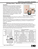
15. XR20ATM Wiring Diagram
The left side of the gure below illustrates the KIT-ATM-D (Dial-Up) wiring
diagram. The right side of the gure below illustrates the KIT-ATM-N
(Network with Dial-up Backup) wiring diagram.
�
16. XR20ATM System Information
Account Number _______________________________________________
Address ______________________________________________________
Phone Number _________________________________________________
Control Panel IP Address ________________________________________
iCOMSL IP Address_______________________________________________
/