Maytag iQ Zone Zoning System User manual
- Category
- Thermostats
- Type
- User manual

User’s Manual


CONTENTS
1. WARNINGS, ENVIRONMENTAL POLICY AND CERTIFICATIONS ..................................................... 4
1.1. Warnings..........................................................................................................................................4
1.2. Environmental Policy ....................................................................................................................... 4
2. OVERVIEW ............................................................................................................................................5
3. IQ CONTROLLER ..................................................................................................................................5
4. LOCAL ZONE THERMOSTATS.............................................................................................................5
4.1 Thermostat Display Icons ................................................................................................................. 5
4.2 Mode Display ....................................................................................................................................6
4.3 Activating and Deactivating a Zone (Thermostat ON/OFF) .............................................................. 7
4.4 The user Setup Screen ..................................................................................................................... 8
4.5 Adjusting de Temperature Setpoint. Manual Control ........................................................................ 9
4.6 Automatic (Programmed Schedule) Temperature Setpoint Control Overview................................ 10
4.7 Switching to Automatic Setpoint Control......................................................................................... 11
4.8 Automatic Setpoint Control – Preparation and Planning................................................................. 12
4.8.1 Setpoint Changes within a Day ................................................................................................ 12
4.8.2 Setpoint Changes within a Week ............................................................................................. 13
4.8.3 Planning ................................................................................................................................... 15
4.9 Automatic Setpoint Control – Procedure for entering a Schedule................................................... 15
4.10 Automatic Setpoint Control – Viewing an Existing Program Schedule ......................................... 18
4.11 Automatic Setpoint Control – Modifying and Existing Program Schedule..................................... 18
4.12 Temporarily Overriding an Automatic Setpoint ............................................................................. 18
4.13 Sleep Mode (One Touch Setback)................................................................................................ 19
4.14 Activating Sleep Mode ..................................................................................................................19
4.15 Cancelling Sleep Mode ................................................................................................................. 19
4.16 Local Ventilation Mode..................................................................................................................20
4.17 Activating Local Ventilation Mode ................................................................................................. 20
4.18 Cancelling Local Ventilation Mode................................................................................................ 20
4.19 Accessing Another Zone from any Thermostat............................................................................. 21
4.20 Temperature Measurement .......................................................................................................... 22
4.21 Location of the Thermostats ......................................................................................................... 22
5. ACCESSORIES.................................................................................................................................... 23
6. SYSTEM ERROR INDICATIONS.........................................................................................................23

4
1. WARNINGS, ENVIRONMENTAL POLICY AND CERTIFICATIONS
1.1. Warnings
For your safety and the equipment protection, follow the following instructions:
• Do not operate the system when wet or with wet hands.
• Connect the power supply cable, before connecting the AC power.
• Perform any connection or disconnection with the power supply powered off.
• Verify that there is no short circuited connection in the connectors between
different cables or with ground.
• Verify for any abnormality in the wiring.
1.2. Environmental Policy
Do not ever dispose of this equipment with household waste.
Electrical and electronic products contain substances that can
be harmful to the environment if they are not given proper
treatment. The symbol of the crossed container indicates
separate collection of electronic equipment, unlike the rest of
urban garbage. For proper environmental management, the
equipment to be disposed must be taken to the proper collection
center at the end of its lifespan.
The components part of this equipment can be recycled.
Therefore, follow the existing regulations on environmental
protection in your area.
The unit must be delivered to your dealer if it is being replaced
or sent to a specialized collection center if discard.

5
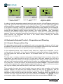
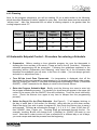
2. OVERVIEW
Thank you for purchasing the iQ Zonesystem. As one of the most advanced systems on the
market, it provides you with the most comfortable temperature for each room or group of rooms
independently.
When the system is installed in your home, all of the individual spaces are grouped into two to
eight separate zones. Each zone typically includes at least one room and several supply
registers. The controls installed with the system have been configured to reflect this zone
grouping. Each zone has also been assigned a “weight” which roughly indicates its percentage
of the overall home floor space.
The system is provided with one thermostat in each zone so that you can set the desired
temperature and other features.
iQ Zone allows you to:
9 Turn off the cooling and/or heating of empty
rooms so that you can use energy efficiently.
9 iQ Zone takes advantage of the location and
environment of each room. For instance, a
room that is situated in a shaded area requires
less cooling power in order to lower the room’s
temperature, while rooms exposed to full
sunlight, usually require less power to heat
them up.
9 iQ Zone uses one iQ controller, and several
small thermostats, which have unobtrusive
and simple designs with low visual impact
so that they do not affect the decoration style
of your home.
3. IQ CONTROLLER
Every iQ Zone system has one iQ Controller as well as local zone thermostats. Note that you
always have the choice between operating the system by zones as described in this document,
or operating as a single entity like a typical non-zoned system (by temporarily disabling zone
control operation). See iQ Drive User’s Manual for details of its operation.
4. LOCAL ZONE THERMOSTATS
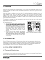
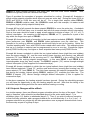
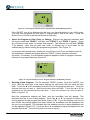
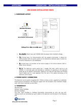
4.1 Thermostat Display Icons
It is important to become familiar with the symbols that you will see on your thermostat. Review Figure 2
below to help understand what you see in the display screens.
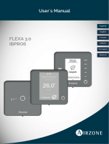
Figure1 – Typical Zone Assignment for a Home
Zone1
68 F
Zone2
OFF
Zone3
OFF
Zone 4
64 F
Zone5
70 F

6
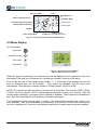
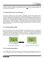
4.2 Mode Display
Icon identification
Stop mode
Ventilation mode
Cool mode
Heat mode
Figure 3 – Normal Screen in Cool Mode
(Manual Setpoint Control example)
When the system is operating, one of these icons will be displayed on the right side of the zone
thermostat.(The stop icon is reserved for a forced stop situation, such as a fire alarm.)
Time of day and day of the week (single number 1 – 7, at the top of the display) are set and
may be changed from the iQ Controller. They cannot be changed from the local zone
thermostats. Note that time is always shown in “military format” (00:00 to 24:00).
NOTE: The operating mode can only be set with the iQ Controller. This includes HEAT, COOL,
E-HEAT (for heat pumps), AUTO (autochangeover between heating and cooling), FAN ON
(system-wide ventilation), and zone control enabled or disabled. Other options are available as
well. See the User's Manual for that device for further information.
The descriptions in this manual apply to version 2.0.x thermostats matched with version 2.0.x
zone modules. With this combination of components, the first touch to the thermostat screen
turns on a backlight for 5 seconds, and different setpoints for heating and cooling are available.
Time Programming Icons
Manual Setpoint Operation
Day of the Week
Time
Sleep Mode Icon
V
entilation Mode
Cooling Mode
Heating Mode
A
irzone Icon
Change Arrows
(Increase/Decrease)
Room Temperature
Automatic Setpoint Operation
ON/OFF
Figure 2 – Summary of Zone Thermostat Display Icons

7
4.3 Activating and Deactivating a Zone (Thermostat ON/OFF)
If you do not wish to provide heated or cooled air to a particular zone, you can deactivate that
zone. Note that any deactivated zone will still have air provided to it under certain
circumstances, including:
• if the iQ Controller system is set to enable system-wide ventilation (Fan Mode = ON)
• if zone control operation is disabled via the iQ Controller
• when dehumidifying in cooling mode
• during a defrost operation (heat pumps only).
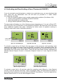
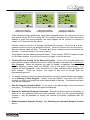
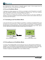
The thermostat will display one of the following screens depending on if it is set to ON or OFF,
and if the zone is set for automatic or manual setpoint operation. Be aware that in the ON mode
some additional symbols may show, indicating the active mode of operation (cooling or
heating), sleep mode, and/or ventilation operation.
Figure 4A - ZoneOFFFigure Figure 4B –Zone ON Figure 4C – Zone ON
To activate a zone that is off (Figure 4A) and return to the previously used operating mode
(Manual or Auto Setpoint Control), touch the ON/OFF icon briefly. After a momentary delay, the
thermostat will change to the User Setup screen (shown below) for 4 seconds, then return to the
appropriate Zone ON screen shown above. There are two User Setup screens, depending on
whether Manual Setpoint Control or Automatic Setpoint Control is in use (Figures 5A or5B
below).
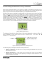
Figure 5A - User Setup Screen Figure 5B - User Setup Screen
(Manual Setpoint Control) (Automatic Setpoint Control)
To activate a zone that is off and also select the operating mode (Manual or Auto Setpoint
Control), touch the Airzone icon briefly. After a momentary delay, the thermostat will change to
the screen shown below for 4 seconds, with the ON/OFF icon blinking. Touch the hand icon for
Manual Control or the “A” icon for Auto/Program Control.
6 .
09:13
76F
4.
14:21
73f
A
4.
09:11
77f
ON/OFF Icon
Airzone Icon
A
1 .
09:10
5.
09:12
77f

8
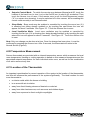
To turn off an active zone, first make a brief touch anywhere in the screen. After a momentary
delay, one of the User Setup screens shown above will be displayed for 4 seconds, during
which time a touch to the ON/OFF icon will deactivate the zone. When the zone is deactivated,
it will show the Zone OFF screen (Figure4A).
4.4 The User Setup Screen
For the user to make a change in his/her preferences for a particular zone, it is necessary to
enter the User Setup Screen in that zone’s local thermostat. With the zone activated as
described in the previous section, from the Normal Screen (Figure 3) make a brief touch
anywhere on the screen. For component combinations that support it, the backlight will
illuminate immediately. After a momentary delay, the User Setup Screen (Figure 5A or 5B) will
be displayed for approximately 4 seconds. From this screen the zone can be turned off or on as
described above. At this time the setpoint for the current mode of operation can be adjusted as
described in the following sections. If the iQ controller is in any mode other than OFF, the icon
for heating or cooling will flash briefly to indicate which of these is the active mode.
If the Airzone icon is touched while the User Setup screen is displayed, a Mode Selection
screen will appear, which permits selection of other options, including manual versus
auto/program control, ventilation, sleep mode, and program scheduling. Details for these
options are discussed elsewhere in this manual.
If the zone is not activated (turned on), no User Setup screen will appear. In that case a single
touch to the Airzone icon will allow mode selection as described above.
If the center of the User Setup screen is touched and held for a couple of seconds, the local
zone number will be identified. After a few seconds the display will return to the Normal Screen.
See also Accessing Another Zone From Any Thermostat, later in this manual.
Temperature Setpoint– General
The iQ Zone system supports dual temperature setpoints which apply separately to heating and
cooling.If AUTO (autochangeover) mode is selected at the iQ Controller, the selection between
starting in heating and cooling is made based on whichever demand is greater at the time.
If a zone thermostat is turned off (deactivated), it remembers the setpoint (either manual or
automatic) and re-applies it when that zone is turned back on.Setpoint adjustment may be
6 .
09:13
A
Figure 5C.
User Setup Screen (from Off)

9
manual or automatic, as described in the following sections. Note that it is possible to have
some zones under manual control and some under automatic control.
Note that the system may not appear to respond immediately to a change in setpoint. First of
all, in order for a system which is off to start up, a minimum start demand (created by the
difference between each zone’s room temperature and its setpoint) must exist. If the demand is
too small, it may not start. Secondly, the zone will not be provided with air flow until all of its
dampers have opened (usually this takes a few seconds per damper).
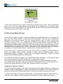
4.5 Adjusting de Temperature Setpoint. Manual Control
In order to adjust the temperature setpoint manually, the control must be (a) in the Manual
Setpoint mode, and (b) turned on (activated, as described above). The screen should appear
with the “hand” icon appearing to the left of the temperature value in the normal ON screen, as
in Figure 6B.
If it is not already in Manual Setpoint mode, check that the zone is off (as in Figure 4A). If not,
shut off the zone by (a) touching anywhere in the screen, then (b) touching the ON/OFF icon.
With the zone off, touch the Airzone icon once. This will display a “hand” icon and an “A” in a
box above the blinking ON/OFF icon (as in Figure 6A below). Touch the hand icon to select
Manual Setpoint control. The zone will also be activated. After a couple of seconds the screen
will show the “hand” icon as in Figure 6B along with current room temperature.
Figure 6A.–Control Mode Figure 6B.–Manual Mode
Selection Screen Active
In order to view and/or adjust the temperature setpoint(s) when the zone is active (as in Figure
6B), first go to the User Setup screen by touching the screen once. The temperature setpoint is
now displayed, and it may be adjusted up or down by briefly touching the up arrow or down
arrow displayed on the screen. If iQ mode is set to COOL, the cooling setpoint will be displayed
for adjustment along with the cooling icon (Figure 6C). If iQ mode is set to HEAT or E HEAT,
the heating setpoint will be displayed for adjustment along with the heating icon (Figure 6D). If
iQ mode is AUTO (Autochangeover), the cooling setpoint will first be displayed with the arrows
for 1 second, then the heating setpoint will be displayed with the arrows for 1 second. The
setpoint is adjustable in increments of 1°F.
4 .
14:38
77
f
4 .
14:37
A

10
Figure 6C. – Manual Cool Figure 6D. – Manual Heat
Figure 6C
Set point Adjustment Figure 6D Set point Adjustment
After three seconds, the thermostat will return to the normal screen, showing the ambient
temperature as in Figure 6B.
4.6 Automatic (Programmed Schedule) Temperature Setpoint Control
Overview.
Automatic setpoint control is most advantageous when the desired changes to the setpoint(s)
are very repeatable day to day throughout a season. Some homeowners may simply want to
use automatic setpoint control as a matter of personal preference. In addition, using automatic
adjustment of set points provides an easy way to achieve optimum energy efficiency, since
demand and energy usage can be automatically reduced based on a known schedule. This
feature may be activated for all, some, or none of the zones. In order for this feature to operate,
the user must create (by making entries at the zone thermostat) setpoint schedules or
“programs” for any of the following days or groups of days:
• Individual days 1 through 7 (where 1 = Monday, 7 = Sunday, etc.)
• Days 1-5 (weekdays)
• Days 6-7 (weekends)
• All days 1-7 (every day)
For any of the above, up to three time blocks called “programs” may be defined (by making
entries at the zone thermostat). Each of these time blocks is associated with a pair of
temperature setpoints (one for cooling, one for heating). Note that it is not necessary to set up
all of the days with programs nor is it necessary to set up all three programs for any day. The
time spans of the different programs may overlap within a day, and a day may be covered by
both an individual day program and by a group of days program. The temperature setpoint
which will be used at any particular time is determined based on priority (explained later).If there
is time within a day or a day within a week that is not covered by at least one program, the zone
is turned off (deactivated) for that period. By wise planning and usage of these programs, taking
into account their priorities, one can create personalized setback schedules with as many as 6
automatic setpoint changes occurring in one day.
Once entered, any of the programs for any of the days or group of days may be later modified
or temporarily turned off. When programming the schedule, the user can choose the set points
desired for cooling and heating, thus avoiding to have to change the set points for each season.

11
In general, setting up schedules involves the following steps for each zone for which automatic
setpoint control is desired:
• Plan out the schedules you want to use.
• Turn off (deactivate) the local zone thermostat.
• Enter the program schedule mode on the thermostat.
• Select the day or group of days to which the schedule will apply.
• Create one, two, or three “programs” (PROG 1, PROG 2, PROG 3) which are to apply to
that day or group of days, specifying for each:
o Time of day when that program schedule starts
o Time of day when that program schedule stops
o A cooling temperature setpoint and a heating set point for that program, for the
time block defined
• Exit the program schedule mode.
• Enable Automatic Setpoint Control operation (as opposed to Manual Control).
• Turn on (activate) the zone.
• Repeat the process for any other day or group of days as desired.
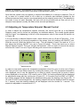
4.7 Switching to Automatic Setpoint Control
In order to run the zoning system utilizing program scheduled temperature setpoints, the control
must be (a) in the Automatic Setpoint control mode, and (b) turned on (activated, as described
above). The screen should appear with the “A” in a box icon appearing to the left of the
temperature value in the normal ON screen) as shown in Figure 7B below. The following
assumes that a program schedule has already been set up.
If it is not already in Automatic Setpoint control mode, check that the zone is off (as in Figure
4A). If not, shut off the zone by (a) touching anywhere in the screen, then (b) touching the
ON/OFF icon. With the zone off, touch the Airzone icon once. This will display an “A” in a box
and a “hand” icon above the blinking ON/OFF icon (as in Figure 7A below). Touch the “A” in a
box icon to select Automatic Setpoint control. The zone may also be activated, depending on
the schedule and time of day. After a couple of seconds the screen will show the “A” in a box
icon as in Figure 7B along with current room temperature.

12
Figure 7A. – Control Mode Figure 7B. – Automatic Mode Figure 7C. – Viewing
Selection Screen Active Programmed Setpoint
In order to view the temperature setpoint when the zone is active in Auto/Program mode (as in
Figure 7B), go to the User Setup screen by touching the screen once. The temperature setpoint
as determined by program schedules is now displayed (Figure 7C) along with the ON/OFF icon.
If the system is currently cooling, the applicable programmed cooling setpoint will be displayed.
If heating, the applicable programmed heating setpoint will be displayed. The up and down
arrows will also appear to allow manual override of the current schedule. (See Temporarily
Overriding an Automatic Setpoint later in this manual.) Note that if no temperature value
appears, there is no schedule entered that turns this zone on for the current time and day. After
three seconds, the thermostat will return to the normal screen, showing the ambient
temperature as in Figure 7B.
4.8 Automatic Setpoint Control – Preparation and Planning
4.8.1 Setpoint Changes within a Day
The planning process should be considered for each zone separately. However, at first it may
be easiest to assume that all zones will follow the same setpoint schedule through each week.
At the end of the process you can adjust the zones to individualize them.
In the explanation below, each “setpoint” really refers to a single pair of setpoints, one for
cooling and one for heating. If you are only interested in setting one of these for the schedule,
you may ignore the other one and leave it at its default value (85°F for cooling, 65°F for
heating).
The first step in creating a setpoint control plan is determining if there are times during each
week when you want the zone to be off. (For the rest of the time, assume you will use a
“baseline” setpoint from which you will take exceptions.) Next assign a single setpoint for each
day as if only one value could be used (for the time when you want the system to be providing
air to that zone). This will be used for the lowest priority program, PROG 3. This baseline would
usually define operation that applies for the longest time in any day. Often it will cover an entire
day or group of days (from start time 00:00 to end time 23:59 every day).
Then consider for each day if and for what times you want to take exception to this single
baseline setpoint. You will have two different values you can use for exceptions, and the
duration of these exceptions would normally be less than that of PROG3. Typically it is
desirable to start and end the day with the same setpoint. Exceptions usually are applied for a
narrower time span, embedded within the time span defined for PROG3. Use PROG2 to make
an exception (apply a different setpoint) that starts later than and ends before PROG3. Use
4.
14:37
4.
14:38
74f
4.
14:39
76f
A A A

13
PROG1 to make another exception that starts later than and ends before PROG2. Thus,
PROG1 will typically have the narrowest time span.
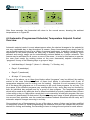
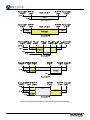
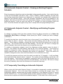
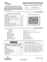
Figure 8 provides five examples of program schedules for cooling. Example #1 illustrates a
simple single setpoint schedule which does not span an entire day. During the times 00:00 to
05:00 and 20:00 to 23:59 this zone will be off. For a single level setpoint either PROG1,
PROG2, or PROG3 could be used. But if PROG3 is used, as in this example, it is easier to add
exceptions (higher priority setpoint blocks) later.
Example #2 first of all expands the base setpoint (PROG3) to cover the entire day. A schedule
from 00:00 to 23:59 will carry over to another day with the same schedule without interruption.
Such a time span should be used to apply a base setpoint to blocks of days (1-5, 6-7, or 1-7)
without interruption. An exception to that setpoint, PROG2, at 73°, operates for a part of the
day within the longer time span of PROG3.
Example #3 shows two levels of exception to the base setpoint schedule (PROG3). PROG2 is
given preference over PROG3, and PROG1 takes precedence over the other two. This
example is for cooling; a different schedule would most likely be set up for heating. Notice the
“inverted wedding cake” form, with PROG levels nested within each other. This example shows
that up to 6 changes in setpoint can be programmed to occur in one day. Exceptions (higher
priority PROG levels) may use higher or lower setpoints than lower priority PROG levels.
Example #4 shows a schedule in which the two typical setback times (night time and midday)
have the same setpoint, 74°, and the most active times (morning and evening) use different
setpoints (72° from PROG 2 in the morning and 71° from PROG 1 in the evening).The thick
lines represent the cooling setpoint temperatures. In this case PROG 1 and PROG 2 are
interchangeable since they don't overlap. The PROG 3 setpoint (74°) carries through midnight
without interruption (if this is applied for consecutive days).
Example #5 shows a schedule in which the two typical setback times (night time and midday)
have different setpoints, 74 and 76°, and the most active times (morning and evening) use the
same setpoint (72° from PROG 2). The thick lines represent the setpoint temperatures. Note
that during the midday, highest priority PROG 1 setpoint (76°) overrides the other two. The
PROG 3 setpoint (74°) carries through midnight without interruption (if this is applied for
consecutive days).
In the above examples, the heating setpoint has been ignored. During the scheduling process
you will have the opportunity to vary the heating setpoint as well. Note that the timing of the
scheduled setpoint changes will be the same whether heating or cooling.
4.8.2 Setpoint Changes within a Week
In a similar manner, there are different program schedule options for days of the week. Plan to
apply a “baseline” daily schedule (as described above) to the entire week (days 1-7), to
weekdays (days 1-5), and/or to weekends (days 6-7). Then, if you wish to make an exception
to that multi-day schedule, add a program schedule for an individual day (1 or 2 or 3, etc.). A
program entered for any single day will take precedence over a program entered which covers
the same day as part of a group of days.

14
Figure 8 – Programming Examples for Automatic Setpoint Control (Cooling)

15
4.8.3 Planning
Now, for the program schedule(s) you will be creating, fill out a table similar to the following,
which describes Example #3 above, applied to every day. Note that times must be entered as
“military time”. Also, the thermostat will not allow a heating setpoint to be greater than the
cooling setpoint minus 2°F.
Day(s)
Program
(1, 2, or 3)
Start
Time
Cool
Temperature
Setpoint
Heat
Temperature
Setpoint
End Time
1 16:00 72° 70° 20:00
2 05:00 73° 71° 22:00
1234567
3 02:00 75° 69° 23:00
4.9 Automatic Setpoint Control – Procedure for entering a Schedule
• Preparation. Before creating a time schedule program, be sure the thermostat is
showing the time and day of the week. (These are set in the iQ Controller.) Otherwise
schedule programming will be prevented. Following the guidelines explained in the
preceding section (Preparation and Planning), write down all of the information that
describes the schedules you will enter, in the form of a table. (You can always go back
and add to or adjust them later.)
• Turn Off the Local Zone Thermostat. If a temperature is displayed, shut off the
thermostat for the zone you will be programming by (a) touching anywhere in the screen,
then (b) touching the ON/OFF icon.(See Activating and Deactivating a Zone (Thermostat
ON/OFF).) Wait 3 seconds for the display to return to the Normal Screen.
• Enter the Program Schedule Mode. Briefly touch the Airzone icon once to enter into
the program scheduling screens. The symbol of a clock face will appear in the upper left
corner of the screen, and the ON/OFF icon will be blinking. Touch the clock icon briefly
once. (Touch the Airzone icon again at any time to escape from the programming
process.)
• Select the Day(s) For the (First) Schedule. See Figure 9. “1” will appear, blinking, in
the day of week part of the screen (for Monday), along with the up and down arrows.
Select the day(s) you wish to enter a program for, then touch the Airzone icon to save it
and proceed. Touching ▲ will advance through 1, 2, 3, 4, 5, 6, 7, then 12345, then 67,
then 1234567, then 1 again, etc. Touching ▼will go backwards through the list. For
example, touching ▼once will change from 1 (Monday) to 1234567 (all week) in one
touch. Note that in order to enter or view a schedule for a different day or set of days,
you must escape and start the process from the beginning.

16
1 .
16:10
Figure 9 – First Program Schedule Screen: Day Selection (Default Monday Shown)
If the ON/OFF icon is not displayed at this time, you have forgotten to turn off the zone.
You may view programs but not enter or change them if this is the case. Touch the
Airzone icon to return to the Normal Screen at this point.
• Select the Program to View, Enter, or Change. After the day has been selected, both
the clock symbol and “PROG 1” will flash, and “PROG 2” and “PROG 3” appear. Touch
any of these to view, enter, or change that program. The selected one will flash ("PROG
1" by default). Note that you may view, enter, or change any or all of these for the
selected day(s) without leaving the programming process. See Figure 10.
If a program has already been entered for one of these and if it has not been turned off,
the temperature setpoint will appear after the “PROG” number has been selected
(touched). Conversely, if no temperature setpoint appears, either no program has been
entered or its program has been turned off.
Figure 10 –Program Schedule Screen: Program Selection (All Weekdays Shown)
• Entering a New Program. For the selected “PROG” number, touch the ON/OFF icon
once. With the clock icon in the corner flashing (for start time), the hour value will now
flash. Touch the ▲ or ▼ as needed to set the hour for the program start time. Touch the
Airzone icon once to save it. Next the minutes value will flash. Touch the ▲ or ▼ as
needed to set the minutes for the start time. Touch the Airzone icon once to save it.
Refer to Figure 11A.
Next the temperature setpoint will flash, and the snowflake icon will appear. This
indicates that this is the cooling setpoint. Touch the ▲ or ▼ as needed to adjust the
cooling setpoint for this program time block (Figure 11B). Touch the Airzone icon once to
save it.After the cooling setpoint has been saved, the snowflake icon will disappear and
the sun icon will appear. This indicates that the heating set point is being displayed and
can be adjusted (Figure 11C). Touch the ▲ or ▼ as needed to adjust the setpoint for this
program time block. Touch the Airzone icon once to save it.
1 2 3 4 5
--:--
A

17
Figure 11A – Program
Schedule Time Selection
Figure 11B – Program
CoolingSetpointSelection
Figure 11C – Program
HeatingSetpointSelection
If the schedule being modified has never been changed before, the setpoints will have
their default values, 85°F for cooling, 65°F for heating. Note that if you raise the heating
setpoint or lower the cooling setpoint, the other setpoint will be “pushed” to maintain a
margin of 2°F between the two values.
Now the clock icon with the “X” through it will flash (for end time). Touch the ▲ or ▼ as
needed to set the hour for the program end time. Touch the Airzone icon once to save it.
Next the minutes value will flash. Touch the ▲ or ▼ as needed to set the minutes for the
end time. Touch the Airzone icon once to save it.
The program has now been entered and saved. Touch another “PROG” number to enter
it in the same manner, or touch the Airzone icon again to exit the process.
• Turning Off and Turning On an Entered Program. To turn off a program which has
been entered (without clearing the entries), follow the above procedure up to Entering a
New Program. When the program you wish to disable is displayed (start time and
setpoint showing), simply touch the ON/OFF icon at this point in the process. The
setpoint will then disappear. Note that there is no other indication that a program has
been entered. Touch the Airzone icon again at any time to escape from the
programming process.
• To restore a program which has been entered but turned off, follow the above procedure
up to Entering a New Program. Simply touch the ON/OFF icon when the “PROG”
number you wish to re-enable has been selected and is flashing. The setpoint and start
time will then reappear.
• Exit the Program Schedule Mode. At any point in the above steps, touch the Airzone
icon again. The Normal Screen will again be displayed.
• Repeat for Additional Program Schedules. Repeat the above steps as necessary to
enter all of the schedules that have been planned. Note that for typical temperate
climates it may be desirable to modify the content of program schedules with the
seasons.
• Enable Automatic Setpoint Control. See Switching to Automatic Setpoint Control
above.

18
4.10 Automatic Setpoint Control – Viewing an Existing Program
Schedule
Enter the program scheduling mode as described in the preceding section. Next, select the day
or days for the schedule you wish to view. Once a “PROG” number is flashing, the start time
and cooling temperature setpoint are displayed if a schedule has already been created and
applied to the selected day(s). (Note that schedule information will not be displayed if the
program has been turned off).Touch the temperature display to switch between cooling and
heating set points. Touch the clock icon with the “X” through it to view the program block end
time. Touch the Airzone icon again at any time to escape from the programming screens.
4.11 Automatic Setpoint Control – Modifying and Existing Program
Schedule
To change a program which has been entered, follow the above procedure up to Select the
Program to View, Enter, or Change. Select (touch) the “PROG” number you wish to change.
(It will flash.)
To modify the start time, touch the clock icon in the corner if it is not flashing. Now touch the
hours value for about 1 second. The number will start flashing, and the ▲ or ▼ icons will
appear. Touch these as needed to change the value, then touch the Airzone icon to save the
new entry. The minutes value will now start flashing. Use the ▲ or ▼ icons to change the
value (if desired), then touch the Airzone icon to save the new entry.
To modify a temperature setpoint, touch the displayed cooling setpoint value for about 1
second. The number will start flashing, and the ▲ or ▼ icons will appear. Touch these as
needed to change the value, then touch the Airzone icon to save the new entry. Next the
heating setpoint value will be displayed with arrows for adjustment. Touch the arrows as
needed to change the value, then touch the Airzone icon to save the new entry.
To modify the program end time, touch the clock icon with the “X” through it. It will now flash.
Now touch the hours value for about 1 second. The number will start flashing, and the ▲ or ▼
icons will appear. Touch these as needed to change the value, then touch the Airzone icon to
save the new entry. The minutes value will now start flashing. Use the ▲ or ▼ icons to change
the value (if desired), then touch the Airzone icon to save the new entry.
4.12 Temporarily Overriding an Automatic Setpoint
When running with Automatic Setpoint Control, it is possible to temporarily override a scheduled
temperature setpoint. Go to the User Setup screen by touching the screen once. The
temperature setpoint as determined by program schedules is now displayed (Figure 7C) along
with the ON/OFF icon. The up and down arrows will also appear as shown in Figure 7C. Touch
these arrows to adjust and override the scheduled setpoint. At the end of the currently active

19
schedule time block (program), the setpoint(s) will return to follow the originally programmed
schedule. Note that overriding a scheduled setpoint does not change the actual schedule, but
only overrides it temporarily.
4.13 Sleep Mode (One Touch Setback)
This feature provides an easy way to trigger a temperature setpoint shift, typically used to
conserve energy such as when the home is unoccupied during the day. The setpoint shift is in
the direction which will save energy (increasing when cooling, decreasing when heating). When
activated, it will change the setpoint temperature by 1°F every 30 minutes until the setpoint has
changed by 4°F. When deactivated, the setpoint temperature will return to the original value (set
by the manual or automatic method). Sleep mode will work in both manual or automatic
setpoint operation. If the iQ controller is in AUTO (autochangeover) mode and Sleep Mode is
active, Sleep Mode will be automatically cancelled if the system needs to switch from cooling to
heating or vice-versa.
4.14 Activating Sleep Mode
The zone to which you want to apply Sleep Mode must be turned on (active). To enter Sleep
Mode, touch the Airzone icon on the screen twice. A mode selection screen will be displayed
including the ventilation and sleep icons as shown in Figure 12A. Touch the Sleep Mode icon
(crescent moon). The Sleep Mode icon will now continue to be displayed after the screen
reverts to the Normal Screen (Figure 12B). (Figures 12A and 12B illustrate the screens with
Manual Setpoint Mode as an example.)
Figure 12A - Activating Sleep Mode Figure 12B - Normal Screen in SleepMode
4.15 Cancelling Sleep Mode
To exit Sleep Mode, touch the Airzone icon once, then touch the Sleep Mode icon (crescent
moon). The Sleep Mode icon will now disappear, and the temperature setpoint will return to

20
that determined by either manual or automatic setpoint control. A few seconds later the
thermostat will return to the Normal Screen (Figure4B).
4.16 Local Ventilation Mode
If heating and cooling equipment are off due to no demand, or the iQ Controller is in the OFF
mode, fan operation (ventilation) may be enabled for individual zones. This Local Ventilation
mode allows some zones to see air circulation while others do not.
(This is different from System-wide Ventilation, which provides air to all zones, regardless of
whether or not they are turned on at the local thermostats. System-wide ventilation can only be
turned on at the iQ Controller.)
4.17 Activating Local Ventilation Mode
A zone must be turned on for Local Ventilation to be available. To activate Local Ventilation Mode, touch
the Airzone icon on the screen twice. A mode selection screen will be displayed including the ventilation
and sleep icons as shown in Figure 13A. Touch the Ventilation icon (fan symbol). The Ventilation icon
will now continue to be displayed after the screen reverts to the Normal Screen (Figure 13B). (Figures
13A and 13B illustrate the screens with Manual Setpoint Mode as an example.)
4.18 Cancelling Local Ventilation Mode
To cancel Local Ventilation Mode, touch the Airzone icon once, then touch the Ventilation icon
(fan symbol). The Ventilation icon will now disappear, and local ventilation for this zone will be
disabled. A few seconds later the thermostat will return to the Normal Screen (Figure 4B). Note
that the Ventilation icon will (still) appear in the Normal Screen whenever System-wide
Ventilation is operating, regardless of the Local Ventilation setting.
Figure 13A.
Activating Local Ventilation Mode
Figure 13B.
Normal Screen in Ventilation Mode
Page is loading ...
Page is loading ...
Page is loading ...
Page is loading ...
Page is loading ...
Page is loading ...
Page is loading ...
Page is loading ...
-
 1
1
-
 2
2
-
 3
3
-
 4
4
-
 5
5
-
 6
6
-
 7
7
-
 8
8
-
 9
9
-
 10
10
-
 11
11
-
 12
12
-
 13
13
-
 14
14
-
 15
15
-
 16
16
-
 17
17
-
 18
18
-
 19
19
-
 20
20
-
 21
21
-
 22
22
-
 23
23
-
 24
24
-
 25
25
-
 26
26
-
 27
27
-
 28
28


Maytag iQ Zone Zoning System User manual
- Category
- Thermostats
- Type
- User manual
Ask a question and I''ll find the answer in the document
Finding information in a document is now easier with AI
Related papers
-
Broan iQ Zone Zoning System User manual
-
Broan PSA4BI User manual
-
Broan PSA4BI Installation guide
-
-
Broan PSH4BI Installation guide
-
Broan PSH4BI Installation guide
-
-
-
-
Broan MGC2T(A,K) User manual
Other documents
-
 Airzone Radiant User manual
-
 Airzone Flexa 3.0 User manual
-
 AirTechnic AIRZONE UNO Installation guide
-
 Airzone Cloud User manual
-
KMC FLEXSTATTM BAC-10000 User manual
-
Uponor Smatrix Space and Space PLUS Owner's manual
-
-
White Rodgers 1F95-1277 User manual
-
 Water Furnace 1F97-1277 User manual
-


