Page is loading ...

DragonflyVR™
SETUP AND USER MANUAL
Page 1 of 14
©2016 Iris Dynamics Ltd. 03-200-001_A0.docx www.irisdynamics.com
DragonflyVR™
FLIGHT YOKE SYSTEM
IDL-20004 FLIGHT YOKE BODY
IDL-300-020 FLIGHT YOKE HANDLE
IDL-30001 INTELLIGENT HANDLE BOARD
SETUP AND USER MANUAL

DragonflyVR™
SETUP AND USER MANUAL
Page 2 of 14
©2016 Iris Dynamics Ltd. 03-200-001_A0.docx www.irisdynamics.com

DragonflyVR™
SETUP AND USER MANUAL
Page 3 of 14
©2016 Iris Dynamics Ltd. 03-200-001_A0.docx www.irisdynamics.com
Contents
SAFETY WARNING ................................................................................................................................................. 4
AVERTISSEMENT DE SÉCURITÉ .............................................................................................................................. 4
1. System Components ............................................................................................................................................. 5
1.1. IDL-20004 Flight Yoke Body.......................................................................................................................... 5
1.2. IDL-300-020 Flight Yoke Handle ................................................................................................................... 5
1.3. IDL-30001 Intelligent Handle Board ............................................................................................................. 5
2. Unpacking, Setup, and First Use ........................................................................................................................... 6
2.1. Introduction ................................................................................................................................................. 6
2.2. Unpacking..................................................................................................................................................... 6
2.3. Handle Installation ....................................................................................................................................... 6
2.4. Driver Installation ......................................................................................................................................... 8
Windows Users ..................................................................................................................................................... 8
2.5. First Use........................................................................................................................................................ 8
3. Force Feedback Effects ......................................................................................................................................... 8
3.1. Default vs. External Effects .......................................................................................................................... 8
3.2. The DirectInput standard ............................................................................................................................. 9
4. Commands ............................................................................................................................................................ 9
4.1. The Arduino ‘Serial’ Monitor ........................................................................................................................ 9
4.2. Commands ................................................................................................................................................. 10
5. Status LED and Buttons ....................................................................................................................................... 11
5.1. Status LED................................................................................................................................................... 11
5.2. Thumb Controls / Hat Switches.................................................................................................................. 11
Left Side Handle – Trim ....................................................................................................................................... 11
Right Side Handle – Other Functionality ............................................................................................................. 11
6. States Explained .................................................................................................................................................. 12
6.1. Active State ................................................................................................................................................ 12
6.2. Standby State ............................................................................................................................................. 12
6.3. Sleep State ................................................................................................................................................. 12
7. Software Updates ............................................................................................................................................... 13
8. Maintenance ....................................................................................................................................................... 13
9. For More Information ......................................................................................................................................... 14

DragonflyVR™
SETUP AND USER MANUAL
Page 4 of 14
©2016 Iris Dynamics Ltd. 03-200-001_A0.docx www.irisdynamics.com
SAFETY WARNING
WARNING: SERIOUS INJURY MAY RESULT FROM IMPROPER USE AND/OR HANDLING. RISK OF ELECTRIC
SHOCK AND STRONG MAGNETIC FIELD HAZARD - DO NOT OPEN. ACTUATOR CAN MOVE QUICKLY AND
WITHOUT WARNING - KEEP CLEAR OF HANDLE. UNIT IS HEAVY - HANDLE WITH CARE - UNPLUG BEFORE
MOVING - DO NOT DROP. PRECISION ELECTRO-MECHANICAL DEVICE. THIS UNIT IS NOT A TOY. NO
USER-SERVICEABLE PARTS INSIDE. DISCONNECT POWER AND USB CABLES BEFORE SERVICING. NEVER
PICK UP THE UNIT BY ITS SHAFT OR HANDLE. DO NOT USE OR STORE THE DEVICE NEAR LOOSE
MAGNETIC MATERIALS.
WARNING: THE PLUG ON THE POWER SUPPLY CORD IS INTENDED TO SERVE AS THE DISCONNECT
DEVICE. ENSURE THE SOCKET-OUTLET IS INSTALLED NEAR THE EQUIPMENT AND IS EASILY ACCESSIBLE.
FOR SUPPORT AND/OR SERVICE SEE THE IRIS DYNAMICS LTD. WEBSITE (WWW.IRISDYNAMICS.COM) OR
CONTACT US VIA EMAIL AT: SUPPORT@IRISDYNAMICS.COM.
AVERTISSEMENT DE SÉCURITÉ
ATTENTION: BLESSURE DE L'UTILISATION ET / OU MAUVAISE MANIPULATION. RISQUE DE CHOC
ÉLECTRIQUE ET CHAMP MAGNÉTIQUE PUISSANT DANGER - NE PAS OUVRIR. ACTIONNEUR PEUT SE
DÉPLACER RAPIDEMENT ET SANS AVERTISSEMENT - ÉVITER LA POIGNÉE. APPAREIL EST LOURD -
FRAGILE - DÉBRANCHER AVANT DE MOUVEMENT - NE LAISSEZ PAS TOMBER. DISPOSITIF DE PRÉCISION
MÉCANIQUES ET ÉLECTRIQUES. CET APPAREIL EST PAS UN JOUET. NO RÉPARABLE PAR L'UTILISATEUR
PIÈCES À L'INTÉRIEUR. DÉBRANCHEZ L'ALIMENTATION ET CÂBLE USB AVANT L'ENTRETIEN. NE JAMAIS
SOULEVER L'UNITÉ PAR SON ARBRE OU POIGNÉE. NE PAS UTILISER OU CONSERVER LE DISPOSITIF PRES
DE MATÉRIAUX MAGNÉTIQUES VRAC.
ATTENTION: LA FICHE DU CORDON D'ALIMENTATION EST DESTINÉ À SERVIR DE DISPOSITIF DE
DÉCONNEXION. VÉRIFIEZ QUE LA PRISE DE COURANT EST INSTALLÉE PRÈS DE L'ÉQUIPEMENT ET EST
FACILEMENT ACCESSIBLE.
POUR SUPPORT ET / OU SERVICE VOIR LA IRIS DYNAMICS LTD. SITE INTERNET
(WWW.IRISDYNAMICS.COM) OU NOUS CONTACTER PAR EMAIL: SUPPORT@IRISDYNAMICS.COM.

DragonflyVR™
SETUP AND USER MANUAL
Page 5 of 14
©2016 Iris Dynamics Ltd. 03-200-001_A0.docx www.irisdynamics.com
1. SYSTEM COMPONENTS
1.1. IDL-20004 Flight Yoke Body
The IDL-20004 Flight Yoke Body is the core of the
DragonflyVR™ Flight Yoke System. It provides
virtual reality variable force feedback and control
loading in response to your flight simulation
software.
1.2. IDL-300-020 Flight Yoke Handle
The optional IDL-300-020 Flight Yoke Handle
provides economical control input for the
DragonflyVR™ Flight Yoke System. The handle
has two thumb-operated hat switches that each
provide 5-way operation—4-way directional
control plus a center-push input.
1.3. IDL-30001 Intelligent Handle Board
The optional IDL-30001 Intelligent Handle Board
allows you to integrate flight yoke handles from
third-party manufacturers. The board supports
up to 10 digital switch inputs and also provides 5
volt power and ground connections.

DragonflyVR™
SETUP AND USER MANUAL
Page 6 of 14
©2016 Iris Dynamics Ltd. 03-200-001_A0.docx www.irisdynamics.com
2. UNPACKING, SETUP, AND FIRST USE
2.1. Introduction
These setup instructions will cover the setup of a DragonflyVR™ Flight Yoke System with the IDL-20004
Flight Yoke Body and IDL-300-020 Flight Yoke Handle. For setups involving third-party flight yoke
handles and the IDL-30001 Intelligent Handle Board, the user will need to devise a mounting system to
attach the handle to the shaft, and then consult the Intelligent Handle Board’s user manual for wiring
instructions. See the “for more information” section at the end of the manual for links to more
information on setting up third-party handles.
2.2. Unpacking
The main housing of the DragonflyVR™ Flight Yoke Body is built from 3/16” structural steel. This
material was selected for two reasons, one being to ensure proper containment of internal dynamic
magnetic fields, and the other being to reduce the need for hold down clamps. As a result of this
material selection the units are very heavy. Great care should be taken to ensure you do not drop your
unit as it is likely to cause significant damage to whatever it lands on. Additionally, it is very important
to never pick the unit up by its shaft or handle. Always pick your unit up with both hands firmly
gripping around the main body of the unit.
This DragonflyVR™ Flight Yoke System relies on the use of strong permanent and dynamic magnetic
fields. Care must be taken to ensure the unit is never brought close to any ferrous (magnetic) metal
shavings. For example, if the unit is brought into proximity with steel shavings (from drilling holes for a
flight deck) these shavings will rapidly adhere to the main shaft which contains numerous strong
permanent magnets. If these shavings are not removed they will enter the internals of the device and
cause serious damage to bearing surfaces, and internal electronics. DO NOT USE OR STORE THE DEVICE
NEAR LOOSE MAGNETIC MATERIALS!
2.3. Handle Installation
To reduce the chances of damage during shipping, DragonflyVR™ bodies and handles are packaged
separately. Prior to powering on your unit you will need to attach the handle to the body. Included
with the Flight Yoke Handle is a parts bag comprised of:
• One 3/16” Allan (hex) key
• One aluminum shaft collar clamp

DragonflyVR™
SETUP AND USER MANUAL
Page 7 of 14
©2016 Iris Dynamics Ltd. 03-200-001_A0.docx www.irisdynamics.com
Assemble as follows:
1. Unpack and unwrap all components onto a level, clean work area.
2. Place the shaft collar clamp on the yoke
handle.
3. Collar shown in place. Rotate the collar so the
split in the collar aligns with the split in the
bottom of the handle shaft.
4. Turn the shaft on the yoke body 90 degrees to
one side, and then turn the yoke body itself
onto its side. This should place the RJ12
connector in the correct orientation and
expose the screw on the bottom of the shaft.
5. Check the orientation and plug the RJ12
connector into the jack inside the handle. The
locking tab on the RJ12 connector should align
with the slot in the handle collar.
6. Slide the yoke handle onto the actuator shaft,
and align the split in the handle collar with the
screw on the bottom of the shaft as shown.
7. Tighten the socket cap screw in the clamping
collar using the 3/16” Allan key.
8. Tighten the socket cap screw until the handle will not pull off the shaft.
9. Your Flight Yoke System is now assembled.

DragonflyVR™
SETUP AND USER MANUAL
Page 8 of 14
©2016 Iris Dynamics Ltd. 03-200-001_A0.docx www.irisdynamics.com
2.4. Driver Installation
Windows Users
For versions of Windows before 10, serial drivers will need to be updated. Windows 10 users can skip
this section.
[Note: This step can also be skipped if command-line communication is not desired. Installing the
drivers is not required, but when the Yoke is plugged in Windows may report a failed driver install. The
yoke will continue to work as a game controller and will be properly recognized by simulator software.]
1. Visit https://www.pjrc.com/teensy/td_download.html and download
https://www.pjrc.com/teensy/serial_install.exe (download link)
2. This file must be run as administrator and simply tells Windows which driver to use for the yoke.
It does not add additional drivers to Windows.
3. This file can be deleted once successfully run.
2.5. First Use
After the unit has been assembled and placed on a secure platform, attach the unit’s power cable to an
appropriate surge protected power source, capable of sourcing 200 watts of power. Upon being
supplied with AC power, the unit’s logic systems will immediately perform a Power-On Self-Test (POST).
If no faults are present, the unit will play a short melody before going to sleep. After a successful POST,
or any time the unit is sleeping, you must perform a “control check” by moving the yoke forwards,
backwards, and to its full limits left and right. As soon as the unit has detected a control check it will
enter “active” mode. Without a connection to a simulator or force-feedback app, the yoke will apply its
default centering force and should simulate a damped spring effect with a little bit of inertia added. This
default behavior is adjustable via serial commands. See Section 4, Commands, for more info.
Next, attach the unit’s USB connection to your computer. Upon being attached to your computer via
USB 2.0 for the first time, the device will enumerate. If the drivers have been updated according to the
steps in “Setup,” two drivers for the Yoke will be installed (Game Controller and Serial). If these steps
were skipped, one driver (Game Controller) will be installed. The unit should now be recognized by your
computer and any simulator or game it runs. Programs may need to be restarted after the yoke is
plugged in for the first time.
3. FORCE FEEDBACK EFFECTS
3.1. Default vs. External Effects
Out of the box, your yoke has built-in effects that center the yoke’s position and dampen quick motions.
In this standalone mode the yoke acts as a traditional non control loading yoke with the added
functionality of having moving trim. These default forces can be modified using serial. See Section 4,
Commands, for more info.

DragonflyVR™
SETUP AND USER MANUAL
Page 9 of 14
©2016 Iris Dynamics Ltd. 03-200-001_A0.docx www.irisdynamics.com
In standalone (default) mode the yoke will not vary forces with airspeed or provide ground bumps/stall
buffeting etc. These effects can be achieved by having your simulation software produce corresponding
force feedback commands using the standard USB protocols. When a program like a flight sim or add-
on sends commands to the Yoke, it will stop its default spring and damper effects until the flight sim or
add-on is closed.
Not all simulators send effects by default. If your yoke feels the same after you start your flight
simulator, check the simulator’s force feedback or control loading settings. You may require an add-on.
3.2. The DirectInput Standard
The DragonflyVR™ Flight Yoke System complies with standard protocols that provide force feedback
commands to USB devices. Therefore, any program that would cause any other USB device to move will
have a similar effect on your yoke. Popular plugins like FS Force or XPForce use this method and will
detect your yoke. They send effects based on the simulator environment.
4. COMMANDS
4.1. The Arduino ‘Serial’ Monitor
Thanks to the great work done by the Arduino and Teensyduino teams, the DragonflyVR™ was
programmed using the user-friendly Arduino environment (with the Teensyduino add-on).
As such, it’s relatively easy to listen to messages coming from the yoke and to send commands.
Here’s how you can hear what the yoke is telling you, and send it serial commands:
1. Install the Arduino IDE: http://arduino.cc/en/main/software. Install version 1.6.5 for best results
(https://www.arduino.cc/en/Main/OldSoftwareReleases#previous)
2. Install the Teensyduino add-on: https://www.pjrc.com/teensy/td_download.html
3. With the flight yoke system connected, open the Arduino environment and select the following
settings:
a. Select the Teensy used in the yoke:
Tools -> Board -> Teensy 3.2 / 3.1
b. Select the communication protocol (serial):
Tools -> USB Type -> Serial
c. Select the serial COM port for the yoke. It will be the last one in the list (highest COM
port number) if it was the last device you installed on your computer.
Tools -> Port -> [select the serial COM port]
4. Open the Serial Monitor by pressing the button in the top right corner, or by pressing
[Ctrl]+[Shift]+[M]
5. Say hi!

DragonflyVR™
SETUP AND USER MANUAL
Page 10 of 14
©2016 Iris Dynamics Ltd. 03-200-001_A0.docx www.irisdynamics.com
4.2. Commands
Syntax
Accepted
Values
Default
Values
Description
about
Displays information about your particular yoke.
factory_reset
Resets all calibration values and settings to a default set. A
calibration will be required after the command, or the yoke
will not wake up.
fx
0-255
210
Changes the gain or “volume” on all roll forces. A value of 0
disables roll forces while a value of 255 allows for maximum
forces. This setting is applied to all roll forces in the yoke.
fy
0-255
230
Changes the gain or “volume” on all pitch forces. A value of
0 disables pitch forces while a value of 255 allows for
maximum forces. This setting is applied to all pitch forces in
the yoke.
iris_damping_x,
iris_damping_y
0-255
15 (x)
20 (y)
Changes the amount of damping on the roll or pitch axis
when no feedback effects have been sent to the yoke.
iris_spring_x,
iris_spring_y
0-255
80 (x)
70 (y)
Changes the force of the default spring effect when no
feedback effects have been sent to the yoke.
iris_inertia_x,
iris_inertia_y
0-255
45 (x)
60 (y)
Changes the force of the default inertial effects when no
feedback effects have been sent to the yoke.
update_firmare
Put the yoke into a bootload state that will look for the
Teensyduino.exe program to provide a firmware update.
reset
Resets the yoke.
standby_timeout
0-65000
300
Changes the number of seconds required for the yoke to
enter standby mode (continues running, but consumes very
little power). Any motion will send the yoke back into active
state.
sleep_timeout
0-65000
7200
Changes the number of seconds required in standby mode
before the yoke goes to sleep. Once asleep, a control check
is required to return to the active state.
sleep
Puts the yoke to sleep.
settings
Display the current state of user settings.
trim_time
0.3-300
16
Change the amount of time required to trim the spring
resting position of the yoke’s default spring force. This value
is in seconds.

DragonflyVR™
SETUP AND USER MANUAL
Page 11 of 14
©2016 Iris Dynamics Ltd. 03-200-001_A0.docx www.irisdynamics.com
5. STATUS LED AND BUTTONS
5.1. Status LED
There is an LED on the IDL-300-020 Flight Yoke Handle that lets you know the unit is awake. The LED is
set to project out the bottom of the handle in normal use, so it does not distract from flight simulation
activities. It can be observed by rotating the handle 90 degrees to the right or left and looking for the
small slot in the base of the handle.
5.2. Thumb Controls / Hat Switches
Left Side Handle – Trim
The Flight Yoke Handle features a 5-way hat switch easily accessible with your left thumb. In the
standalone mode, moving the hat switch forward and back will change the trim and move the center of
the default forces. This allows for trim functionality even when not supported by a simulator, or even
when no simulator is running.
The hat switch also sends button information to the joystick interface. Trim down will show up as a
button 3 press; trim up will show up as a button 4 press. Button assignments for left, right, and center
push are not assigned by default but can be assigned in the simulator or via force-feedback plugin
software.
It is often necessary to install a plugin to bypass the simulator’s trim functionality, as it will apply trim by
modifying the forces and the resting position of your yoke. With your simulator’s trim enabled,
unintended and unrealistic results can come from the trim switch if it isn’t assigned to the correct place.
See Section 9 (“For More Information”) and visit our website for more information.
Right Side Handle – Other Functionality
The Flight Yoke Handle features an identical 5-way hat switch on the right side that can be used for
other functionality in your simulation software such as flaps, brakes, autopilot disconnect, look-around,
etc.

DragonflyVR™
SETUP AND USER MANUAL
Page 12 of 14
©2016 Iris Dynamics Ltd. 03-200-001_A0.docx www.irisdynamics.com
6. STATES EXPLAINED
6.1. Active State
In this state your DragonflyVR™ Flight Yoke System will behave like a control loading / haptic / force-
feedback controller. It could either be applying its default centering forces with an adjustable center
position using the trim switch, or it could be applying external forces sent through the USB interface.
6.2. Standby State
When the yoke hasn’t moved for a while it will go into a standby mode. In this mode the power to many
elements is shut off. The yoke continues to send its position and continues to respond to external force
commands. As soon as any motion in either axis is detected, the yoke goes back to active state. The
default timeout duration can be set using serial command “standby_timeout ####”.
6.3. Sleep State
In sleep state, the yoke will not transmit USB data, and will not apply any forces or make any noises. It is
essentially off. To wake the yoke up, perform a “control check” by moving the yoke forwards,
backwards, and to its limit of travel left and right in a smooth motion. Once you’ve performed the
control check, the yoke will wake up.

DragonflyVR™
SETUP AND USER MANUAL
Page 13 of 14
©2016 Iris Dynamics Ltd. 03-200-001_A0.docx www.irisdynamics.com
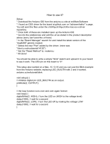
7. SOFTWARE UPDATES
As we make revisions, we will release new versions of the firmware that you can flash onto your yoke.
Visit IrisDynamics.com for the latest firmware build.
Here’s how to install updated firmware on your device:
1. Download the new firmware file from the Iris Dynamics website.
2. Start Arduino.
3. With the flight yoke system connected, open the Arduino environment and select the following
settings:
a. Select the Teensy used in the yoke:
Tools -> Board -> Teensy 3.2 / 3.1
b. Select the communication protocol (serial):
Tools -> USB Type -> Serial
c. Select the serial COM port for the yoke. It will be the last one in the list (highest COM
port number) if it was the last device you installed on your computer.
Tools -> Port -> [select the serial COM port]
4. Open a serial window from Arduino (top right corner of the IDE, magnifying glass).
5. Start ‘teensy’, the Teensy Loader (C:\Program Files (x86)\Arduino\hardware\tools).
6. In the Teensy Loader, click the “Auto” button and ensure it is illuminated bright green (on).
7. Direct the loader to a firmware file (.hex):
a. File -> open HEX file
8. In the Arduino Serial Monitor, type “update_firmware” and press enter to start the re-flash
process.
9. Windows may install a driver at this point. It will happen automatically – let it finish.
10. The Teensy Loader should detect the Teensy is now in a bootload state and upload the hex file.
11. If the upload fails (it will if Windows installed drivers), click the “Auto” button on the Teensy
Loader after the driver install completes and the firmware will upload.
12. Enjoy!
8. MAINTENANCE
Your DragonflyVR™ Flight Yoke System uses self-lubricating bearing surfaces internally and does not
require lubrication. Do not apply any lubricants to the yoke shaft.
The yoke shaft does contain strong magnets and may attract dust over time that should be removed.
You can usually remove the fine particles from the shaft by wiping with a damp paper towel.
The fan vents may also attract dust and may benefit from getting vacuumed if build-up is observed.

DragonflyVR™
SETUP AND USER MANUAL
Page 14 of 14
©2016 Iris Dynamics Ltd. 03-200-001_A0.docx www.irisdynamics.com
9. FOR MORE INFORMATION
DragonflyVR™ firmware, manuals, support, and
user forums
http://www.irisdynamics.com/
Using the XP Force plugin to integrate with X-
Plane
http://www.fsmissioneditor.com/XPForce/
Using the FS Force plugin to integrate with
Microsoft Flight Simulator or Prepar3D
http://fs-force.com/
/