Page is loading ...

www.datataker.com
© 2019 ThermoFisher Scientific
DT90 Range
DT90L and DT90N
User's Manual
A complete guide to:
data acquisition
data logging
programming
sensor wiring
communications
Intelligent Data Logging Products

UM-0090-B1E DT90 Range User Manual Page 2
RG
DT90 Range User’s Manual
© Copyright 2005-2018 Thermo Fisher Scientific Australia Pty Ltd ABN 52 058 390 917
UM-0090-B1E
Warranty
Thermo Fisher Scientific Australia Pty Ltd (“Thermo Fisher”) warrants the instruments it manufactures against defects in
either the materials or the workmanship for a period of three years from the date of delivery to the original customer.
This warranty is limited to, and purchaser’s sole remedy for a breach of this warranty is, the replacement or repair of
such defects, without charge, when the instrument is returned to Thermo Fisher or to one of its authorized dealers
pursuant to Thermo Fisher’s return policy procedures.
The obligations set forth above shall be void with respect to any damage to the instrument resulting from accident,
abuse, improper implementation or use, lack of reasonable care, loss of parts, force majeure, or any other third party
cause beyond Thermo Fisher’s control. Any installation, maintenance, repair, service, or alteration to or of, or other
tampering with, the instruments performed by any person or entity other than Thermo Fisher without its prior written
approval, or any use of replacement parts not supplied by Thermo Fisher, shall immediately void and cancel all
warranties with respect to the affected instruments.
Thermo Fisher shall not be liable for any incidental, indirect, special, punitive or consequential loss or damages resulting
from or arising out of the use of the instrument, In no event shall Thermo Fisher’s liability with respect to the instrument,
the use thereof, this warranty statement or any cause of action related thereto, under any circumstances exceed the
purchase price of the instrument actually paid by purchaser.
Where Thermo Fisher supplies to the customer equipment or items manufactured by a third party, then the warranty
provided by the third party manufacturer shall pass through to purchaser, but only to the extent allowed by the original
manufacturer or third party supplier.
EXCEPT AS EXPRESSLY PROVIDED IN THIS WARRANTY STATEMENT, THERMO FISHER DISCLAIMS ALL
OTHER WARRANTIES, WHETHER EXPRESS OR IMPLIED, ORAL OR WRITTEN, WITH RESPECT TO THE
INSTRUMENTS, INCLUDING WITHOUT LIMITATION ALL IMPLIED WARRANTIES OF MERCHANTABILITY OR
FITNESS FOR ANY PARTICULAR PURPOSE. THERMO FISHER DOES NOT WARRANT THAT THE INSTRUMENTS
ARE ERROR-FREE OR WILL ACCOMPLISH ANY PARTICULAR RESULT. ANY ADVICE OR ASSISTANCE
FURNISHED BY THERMO FISHER IN RELATION TO THE INSTRUMENTS SHALL NOT GIVE RISE TO ANY
WARRANTY OR GUARANTEE OF ANY KIND, AND SHALL NOT CONSTITUTE A WAIVER BY THERMO FISHER.
The Purchaser shall be solely responsible for complying with all applicable local, state and Federal laws with respect to
the installation, use and implementation of the equipment.
Trademarks
dataTaker is a registered trademark of Thermo Fisher Scientific Australia Pty Ltd. All other brand and product names are
trademarks or registered trademarks of their respective holders.
Regulatory Notices
This equipment has been tested and found to comply with the limits for a Class A digital device, pursuant to part 15 of
the FCC Rules. These limits are designed to provide reasonable protection against harmful interference when the
equipment is operated in a commercial environment. This equipment generates, uses, and can radiate radio frequency
energy and, if not installed and used in accordance with the instruction manual, may cause harmful interference to radio
communications. Operation of this equipment in a residential area is likely to cause harmful interference in which case
the user will be required to correct the interference at his own expense.
Please refer to the following table and information for compliance requirements of the DT90 Series.
Domain
Applicable Standards
Safety (Product with Integrated Modem)
AS/NZS 60950.1:2015
EMC
EN 55032: 2015
EN 55035: 2017
EN 61000-3-2: Ed. 4.0 (2014)
EN 61000-3-3: Ed. 3.0 (2013)
AS/CA S042: 2015
FCC & IC
CFR47 FCC Part 15, Subpart B (Class B)
CE RED for Integrated Modem
EN 62311:2008
EN 60950-1:2006+A11:2009+A1:2010+A12:2011+A2:2013
EN 301 489-1 V2.2.1
EN 301 489-19 V2.1.0 (Draft)
EN 301 489-52 V1.1.0 (Draft)
EN 301 511 V12.5.1 (2017-03)
EN 301 908-1 V11.1.1 (2016-07)
EN 301 908-2 V11.1.1.2 (2017-08)
EN 301 908-13 V11.1.2 (2017-07)
EN 303 413 V1.1.1

UM-0090-B1E DT90 Range User Manual Page 3
RG
FCC / IC Statements
This equipment has been tested and found to comply with the limits for a Class B digital device, pursuant to part 15 of
the FCC Rules. These limits are designed to provide reasonable protection against harmful interference when the
equipment is operated in a commercial environment. This equipment generates, uses, and can radiate radio frequency
energy and, if not installed and used in accordance with the instruction manual, may cause harmful interference to radio
communications. Operation of this equipment in a residential area is likely to cause harmful interference in which case
the user will be required to correct the interference at his own expense.
Changes or modifications not expressly approved by the party responsible for compliance could void the user's authority
to operate the equipment.
Cet équipement a été testé et reconnu conforme aux limites d'un appareil numérique de classe B, conformément à la
partie 15 des règles de la FCC. Ces limites sont conçues pour fournir une protection raisonnable contre les interférences
nuisibles lorsque l'équipement est utilisé dans un environnement commercial. Cet équipement génère, utilise et peut
émettre de l'énergie radiofréquence et, s'il n'est pas installé et utilisé conformément au manuel d'instructions, peut
causer des interférences nuisibles aux communications radio. Le fonctionnement de cet équipement dans une zone
résidentielle est susceptible de causer des interférences nuisibles, auquel cas l'utilisateur devra corriger l'interférence à
ses propres frais.
Les changements ou modifications non expressément approuvés par la partie responsable de la conformité pourraient
annuler l'autorisation de l'utilisateur d'utiliser l'équipement.
This product contains modem – FCC ID ZMONL668AM00
Disposal of Product and Batteries
This product is subject to the EU Directive 2012/19/EU for Waste Electrical and Electronic Equipment
(WEEE). As such product must not be disposed of in general waste facilities. Please refer to local
regulations or contact your distributor on how to dispose this product in an environmentally friendly
manner.
Dispose of used batteries via an appropriate recycling facility only.
Warning
dataTaker products are not authorized for use as critical components in any life support system where failure of the
product is likely to affect the system’s safety or effectiveness.
This equipment is compliant with class B of EN55032. In residential environment this equipment may cause radio
interference.
Important: Firmware Version Covered in This Manual
This version of the dataTaker DT90 Range User’s Manual (UM-0090-B1E) applies to the DT90 range of data loggers
(DT90L, DT90N).

UM-0090-B1E DT90 Range User Manual Page 4
RG
Content
Content ...................................................................................................................... 4
Part A – The DT90 ........................................................................................ 6
DT90 Concepts .......................................................................................................... 6
What is the DT90? ........................................................................................................................................ 6
The DT90 Product Family ............................................................................................................................. 6
DT90-Friendly Software ................................................................................................................................ 6
About This Manual ........................................................................................................................................ 6
A Tour of the DT90's Interfaces .................................................................................................................... 7
Getting Started .............................................................................................................................................. 7
Getting Help .................................................................................................................................................. 7
Designing Your Data Logging System .......................................................................................................... 7
Measurements ........................................................................................................... 8
What can the DT90 Measure? ...................................................................................................................... 8
Part B – DT90 Configuration........................................................................ 9
Main Menu.................................................................................................................. 9
Page Description ........................................................................................................................................... 9
Configuration ........................................................................................................... 10
Page Description ......................................................................................................................................... 10
Sensors ....................................................................................................................................................... 10
Global Sensor Settings ............................................................................................................................... 13
Data Transmission ...................................................................................................................................... 16
Alarm ........................................................................................................................................................... 16
Setting ......................................................................................................................................................... 17
Connect .................................................................................................................... 18
Page Description ......................................................................................................................................... 18
Instantaneous Measurement .................................................................................. 18
Page Description ......................................................................................................................................... 18
Measurement .............................................................................................................................................. 19
Load Data ................................................................................................................................................... 19
Get Time ..................................................................................................................................................... 19
Clear Log .................................................................................................................................................... 19
Firmware Update ..................................................................................................... 19
Requirements .............................................................................................................................................. 19
Update Process .......................................................................................................................................... 20
Display Data ............................................................................................................. 20
Page Description ......................................................................................................................................... 20
About DT90 Configuration ...................................................................................... 21
Part C – Sensors & Channels .................................................................... 22
Connector and Pin Assignment ............................................................................. 22
Power and Communication Connector (PC) ............................................................................................... 23
Analog Input Connectors (A1 – A2 – A3 – A4) ............................................................................................ 23
Digital/ Serial Input Connectors (D1 – D2) .................................................................................................. 24
Voltage Output ............................................................................................................................................ 26
Connector Labelling .................................................................................................................................... 26

UM-0090-B1E DT90 Range User Manual Page 5
RG
Part D – References ................................................................................... 27
DT90 Series Specifications .................................................................................... 27
Analog Channels ......................................................................................................................................... 27
Digital Channels .......................................................................................................................................... 27
Data Processing .......................................................................................................................................... 27
Hardware .................................................................................................................................................... 28
Care and Maintenance ............................................................................................ 29
Transport ..................................................................................................................................................... 29
Installation ................................................................................................................................................... 29
Battery Installation, Inspection and Replacement ....................................................................................... 29
Moisture Absorber Replacement ................................................................................................................. 30
Glossary ................................................................................................................... 31
Safety Information ................................................................................................... 32
General ....................................................................................................................................................... 32
Index ......................................................................................................................... 33

UM-0090-B1E DT90 Range User Manual Page 6
RG
Part A – The DT90
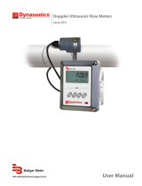
Figure 1: dataTaker DT90N (left); DT90L (right)
DT90 Concepts
What is the DT90?
The DT90L and DT90N dataloggers, are compact all-in-one monitoring modules, designed specifically for remote
measurements, where emphasis is on low power, small size and ease of deployment. Having an analogue 16-bit channel
resolution and digital counters with SDI-12 / MODBUS RTU support it makes it possible to connect various sensors in the
field with minimum time.
Simple connectivity via USB on-site makes it easy to configure and test the deployed monitoring module. Remote
configuration gives the possibility to tune the system to arising needs. Variable sampling and transmission schedules are
possible to set up. The whole design is made to keep it small, simple and effective, meaning; low maintenance, long
uninterrupted working time and money saved!
The DT90 Product Family
The DT90 product family includes the following models:
The DT90L is a low cost, low power Compact variant of data logger
The DT90N is a Nano variant which is smaller model of DT90
DT90-Friendly Software
DT90 Configuration is a desktop based application for programming and monitoring DT90 Series data loggers. This
Config software requires installation in your PC. It provides a totally simple interface to create and set channels, each
channel can have different reading rate.
DT90 Configuration has inbuilt chart to view historic data values and download data. It also possible to trigger
instantaneous measurement.
All software is provided on the CD supplied with your DT90, and updates are available from the dataTaker website,
www.datataker.com (Support/ Downloads section).
About This Manual
This manual is intended for all users of the DT90. It describes:
How to connect sensors and other devices to the DT90's input and output channels.
How to program the DT90 to collect and return data as required.
How to manage the data that the DT90 collects.

UM-0090-B1E DT90 Range User Manual Page 7
RG
A Tour of the DT90's Interfaces
The DT90 have 2 interfaces with the outside world:
Communication/ Power and Sensor Interface
On the bottom part of DT90, there are nine round connectors – in which each connector has a dedicated interface:
Connector PC: External power and communication to PC interface
DT90L only:
Connector A1: 2 x voltage inputs or 2 x current inputs and 2 x 12V voltage excitation
Connector A2: 2 x voltage inputs or 2 x current inputs and 2 x 12V voltage excitation
Connector A3: 2 x RTD (PT100) inputs in 3 wire configuration or 2 x voltage inputs
Connector A4: 2 x RTD (PT100) inputs in 3 wire configuration or 2 x voltage inputs
DT90L and DT90N:
Connector D1: 3 x pulse inputs and 1 x 12V voltage excitation
Connector D2: 1 x SDI12 input and 1 x MODBUS input
Modem Interface
On the top part of DT90, there is coaxial screw connector for main antenna.
Getting Started
Power
DT90 models include an internal 3.6 V Li-ion battery which can power the logger if the main external supply is
interrupted. Several selection for main power are AC/DC adaptor, 12V/ 24V external battery or 9V/ 12V solar panel.
When power is connected and the lid is open, you could observe one LED below the left white terminal will start blinking.
Important: The DT90 is shipped with its internal battery disconnected. We recommend the battery is connected as soon as practical so
that it can charge from the mains adaptor or other external power source.
Connecting to a Host Computer
In order to program the DT90, it is generally necessary to connect it to a "host" computer. There is a cable for Connector
PC for USB connection to a PC. 3. The Windows "New Hardware Found" wizard will then run automatically (if required)
to complete the installation of the necessary drivers.
Launch DT90 Configuration to establish a connection.
Getting Help
This user manual is available in dataTaker website (www.datataker.com), including database of frequently asked
questions, code examples, sensor information, application notes, video tutorials and an online forum.
Designing Your Data Logging System
Data acquisition and data logging are orderly processes and should be undertaken in a systematic way. In order to
obtain effective information efficiently, do the following:
Identify the quantities to be measured.
Select the sensors, considering measurement range, accuracy, stability, ruggedness and cost.
Select the wiring configuration and data rates.
Determine sensor output scaling, that is, the relationship between sensor output voltage/ current and the actual
quantity.
Decide on the sample frequency – don't sample faster than you need to.
Decide on the method of data recovery and alarms.
The remainder of this manual will help you address these questions and then generate a suitable program for your DT90.

UM-0090-B1E DT90 Range User Manual Page 8
RG
Measurements
What can the DT90 Measure?
Analog
Using its analog inputs, the DT90 can directly measure the following:
DC voltage (50mV, 2.5V ranges)
4-20mA current loop
temperature (RTDs)
Digital
The DT90’s counter channels allow the measurement of:
pulse count (32 bit)
Serial
Various “smart sensors” can also be read:
SDI-12 based sensor networks
MODBUS RTU via RS485

UM-0090-B1E DT90 Range User Manual Page 9
RG
Part B – DT90 Configuration
What is DT90 Configuration?
DT90 Configuration is a desktop application to program DT90 series data logger, it will need to be installed on a PC.
This application will set channels, excitation output, data transfer and alarm. It is also possible to plot a chart on historical
data.
Connecting to DT90 Configuration
You can establish a connection to DT90 via USB cable.
Main Menu
Page Description
The Main Menu of DT90 Configuration provides 6 options:
- Configuration – to configure the logger for reading signal from sensors, setting up data transmission and alarms.
- Connect – to establish connection to the logger
- Instantaneous Measurement – to get instantaneous reading from logger, download data, set up time and clear
logged data.
- Firmware Update – to update firmware
- Display Data – to display downloaded data
- About DT90 Configuration – to display software version
Figure 2: Main Menu Windows

UM-0090-B1E DT90 Range User Manual Page 10
RG
Configuration
Page Description
Configuration menu provides simple and intuitive access to the logger’s operation, Select Configuration option from
the main menu to access the configuration window.
Configuration windows comprises the following elements:
- Properties Pane on the right hand side is used to display various setting depending on menu selection. User
can define these setting according to requirements.
- Menus on the left hand side are used to access each configuration setting. There are four menus: Sensors,
Global Sensor Settings, Data Transmission and Alarm. Clicking on a menu will reveal menu items and each
item selection would be displayed in the properties pane.
- The banner area along the top screen contains one Home button which provides a link back to Main Menu and
two information tags: Station Name and Logger Type.
- The bottom of the screen displays Connection Status to the logger.
Figure 3: Configuration Windows
Sensors
Sensors menu is used to create measurement channel based on sensor’s output signal. There are 2 possible “maximum
number” of available channels in a logger unit depending on firmware version, 13 channels (factory default) and 26
channels (optional).
The above selection will determine the number of maximum data point to be recorded in FLASH memory, with 16 MB in
size the logger can hold 260,000 data points (for 13 channels) or 130,000 data points (for 26 channels).
13
channels
Date
Time
Zone
Empty1
Empty2
Empty3
…
Empty12
Empty13
26
channels
Date
Time
Zone
Empty1
Empty2
Empty3
…
Empty25
Empty26
Table 1: Logger memory mapping

UM-0090-B1E DT90 Range User Manual Page 11
RG
Each channel have might be configured by setting the following fields:
Figure 4: Weather Station Sample Program
Input
Signal source for the channel, selected from the list depending on the device.
The drop-down list includes:
- SDI-12 – digital sensors operating in compliance with SDI-12 standard (see SDI-12 (P14))
- Internal analog – measurement of the logger's internal parameters such as: voltage of the built-in battery,
voltage of the external power source, 5V and 12V auxiliary power
- MODBUS RTU – digital sensors operating in compliance with MODBUS RTU standard (see MODBUS RTU
(P14))
- Pulse Counter – predefined pulse sensor necessary for operating a rain gauge (usually tipping bucket rain
gauges), with pulse output
- External analog – measurement of analogue values of voltage and currents from external sensors (see
Analogs (P13))
- Wind Gauge – predefined pulse counter necessary for operating a classic mechanical anemometer – pulse
output only
- Status – predefined pulse sensor for handling logical signal sources 1/0
Name
The Name field includes the name of the given channel defined by the user up to 20 characters. The name might include
any string of ASCII characters.
Parameter
The Parameter field allows to select additional options related to a given input signal type. The example below shows a
drop-down list of available parameters for Internal Battery.
Cycle
The Cycle field allows to define the measurement interval for that particular channel. You can choose intervals ranging
from 1 minute to 24 hours from the drop-down menu. Measurements shall be taken with respect to 00.00 hour of the
logger's time (midnight reference) without the option of entering a time shift. The table below indicates midnight
reference of taking measurements based on time interval values:
5 minutes
interval
Measurement
00:00:xx
Measurement
00:05:xx
Measurement
00:10:xx
…
Measurement
23:55:xx
4 hours
interval
Measurement
00:00:xx
Measurement
04:00:xx
Measurement
08:00:xx
…
Measurement
20:00:xx
Table 2: Midnight reference to measurement interval

UM-0090-B1E DT90 Range User Manual Page 12
RG
The number of seconds shown here as xx depends on the sensor connected to the logger and on the so-called
Measurement Delay available in Global Sensor Settings tab. The time, at which measurement is recorded in FLASH
non-volatile memory is the time of completing a sampling cycle.
In special cases, when sensor requires a longer starting time (i.e. to start up, stabilize the reading after start-up -
Measurement Delay) and while the measurement cycle of a sensor is long (i.e. in order to damp the measurement), a
measurement time shift greater than 60 s may occur, and this is considered normal.
“Other” Interval Option
There is one more way to define sampling intervals by selecting “Other” option in the Cycle field. You will be presented
24 hours check box in hourly basis. Selecting any of the box will prompt the logger to start measurement at the beginning
of the selected hour. This “Other” option will disable a standard measurement interval.
This functionality is particularly useful if the sensors connected to the data logger do not require continuous powering, in
which power will only activated for the time of measurement. Powering up the sensors before measurement and shutting
off the power is preferred for all applications to preserve energy in the data logger.
Figure 5: Internal Channel
Scaling
Values obtained from sensors might be scaled in order to obtain desired output value ranges. Scaling of measurements
applies both to displayed temporary values and the values saved in non-volatile FLASH memory. Users can choose
between two types of scaling. Both options come down to scaling using a linear function.
Figure 6: Scaling - Two points (left) and slope-intercept (right)
x2, y2
x1, y1
y= ax + b

UM-0090-B1E DT90 Range User Manual Page 13
RG
This scaling cannot accept floating point number, thus you will need to use workaround using two points scaling. For
example if you need to define 1 pulse as 0.1 mm for precipitation, because you can’t define 0.1 on “a” component thus
you can use this method:
Figure 7: Scaling to achieve floating point factor
Unit
Each measurement channel might have a defined unit, with which the data are recorded and presented. Unit field might
include up to 10 ASCII characters.
Precision
Precision field allows to determine the precision of decimal points within measurement data either in the display or
transmitted data up to 4 digits (0, 0.1, 0.01, 0.001 and 0.0001). However the setting does not change the method of
saving numbers in the memory, data are always saved in the memory with maximum precision.
Notes: This option does not influence the maximum amount of data saved in the memory.
Alarm
DT90 device allows to configure up to three event alarms. Alarms might be set for any channels, but not more than one
alarm per channel. In order to activate alarm on a given measurement channel, change field Deactivated at the bottom of
its window into the alarm number.
If an alarm is set on one channel, its configuration needs to be completed in Alarm (P16) tab.
Global Sensor Settings
Analogs
This page allows user to set the type of input of 8 analog channels, either as voltage, current or PT100. These analog
channels are located on 4 connectors A1, A2, A3 and A4. This setting is required to set the logger for accepting the
signal.
Figure 8: Analog channel allocations

UM-0090-B1E DT90 Range User Manual Page 14
RG
MODBUS RTU
In this page user can set serial port setting as well as parameters location within MODBUS sensor including sensor
address. Later on after setting up this page user can create channels within Sensors (P10) page.
Figure 9: Serial port configuration
Figure 10: The first 3 MODBUS entries out of 10 entries
There are 9 configuration settings (from A to I) and each of them deals MODBUS block read. Users may utilise these 9
entries for either:
- 9 single parameter reading from a single sensor which have different register location
- 9 blocks read* from a single sensor as long as the total number of channels are within 26
- 9 blocks read* from up to 9 sensors as long as the total number of channels are within 26
Data type and MODBUS functions are configurable on each configuration setting. User may choose data type:
- INT (integer),
- UINT (unsigned integer)
- FLOAT (floating point)
- INT32 (long integer)
- UINT32 (unsigned long integer)
And choose MODBUS functions:
- Coils (function 1)
- Discrete Inputs (function 2)
- Holding Registers (function 3)
- Input Registers (function 4)
Notes: * Block read or block transfer refers to reading action of consecutive MODBUS register using a single command by defining the
number of target registers. The maximum length for block read is 32 registers.
SDI-12
There are 8 sections within SDI12 settings (Figure 11), each setting has one main measurement (M!) with up to 20
parameters and 3 additional measurements (M1! – M3!) with 9 parameters each. Users may choose to use SDI12
version 1.0 (M) or version 1.2 (C), unfortunately it does not support version 1.3 (CC).
After setting up parameter location in this page, user will need to define the channels Sensors (P10) page.

UM-0090-B1E DT90 Range User Manual Page 15
RG
Figure 11: SDI12 Settings
Other Settings
DT90 loggers enable powering measurement equipment from own power source. Depending on the logger model type
the user can choose between:
- 12V – stabilized 12 V voltage from an integrated inverter with maximum current efficiency at the level of 200 mA
(DT90 L) and 100 mA (DT90 N)
- 5V – stabilized 5 V voltage from an integrated inverter with maximum current efficiency at the level of 200 mA
(DT90 L)
The user might apply the aforementioned supply voltage levels, depending on their needs. Please note that activating
inverters for 5V and 12V voltage in one of two modes, that is, active during measurement or always active (Figure 12)
can influence on electricity consumption of the internal battery pack.
After activating the voltage supply the sensors usually need a certain time to stabilise their operating parameters. This
time differs between different sensor manufacturers and models. The Measurement Delay field shows integer numbers
ranging from 0 – 120 s.
It is important to remember that cumulating the delay in initiating measurement with the measurement time might in
particular cases result with incapability to obtain the smallest measurement intervals and data transmission intervals. In
such case unforeseeable delays and irregularities in saving the measurements in non-volatile memory might occur.
Moreover, the logger remains active and its energy intake is higher for the defined period of delay.
Figure 12: Power Output setting
That's why the value entered in Measurement Delay field should be optimally adapted to the applied sensors. Please
consult the sensor manual or manufacturer support to receive information about warm up time.
It is also possible to supply the sensor power at all times, but it is not advised if the logger is using batteries or solar
panels for power.

UM-0090-B1E DT90 Range User Manual Page 16
RG
Data Transmission
Data transmission setting control data connection to 4G network, FTP destination as well as transmission interval. Within
FTP configuration user will need to provide server name and credential, you can also set the number of retries if the
transmission failed.
Figure 13: FTP configuration
Within GPRS configuration, user can set the pin to access SIM card as well as defining APN information. The checkbox
next to Pin entry is used to enable and disable pin feature.
Figure 14: GPRS configuration
The last setting is transmission interval for FTP data, you can have 2 types of interval depending on the limit you defined
within Alarm page. The first one is a normal interval which happen when the reading value is not exceeding alarm limit,
and the next one is alarm interval which happen when the value exceeds defined alarm limit.
Figure 15: Transmission schedule
Alarm
Alarms are triggered based on the value measured for a given channel. Alarm might be triggered by a measured value
exceeding the upper or lower threshold (only one threshold might be selected). The logger will exit from the alarm mode
the measured value does not exceed the set thresholds.

UM-0090-B1E DT90 Range User Manual Page 17
RG
Alarm mode may trigger:
- A change of transmission intervals (settings in Data Transmission tab), however it will not change the sampling
interval on that channels.
- Sending one text message to maximum three destination number.
Alarm Configuration
This setting will allow user to set alarm threshold from three possible alarm events. The selection is limited to upper or
lower threshold exclusively, which mean only one threshold can be selected on every event. There are 3 thresholds in
total which usable across all 26 channels.
Figure 16: Alarm configuration and placement on a channel
SMS Configuration
SMS Configuration page is used to set destination number for SMS, there are 3 numbers available and user
can also set service center for SMS.
Figure 17: SMS Configuration and Alarm Text
Alarm Text
Alarm test is used to define the content of SMS alarm, there are 3 entries available each is related to
destination number in SMS Configuration (see Figure 17).
Setting
Setting page is used to set station name on the logger and time. There is a checkbox to enable time synchronisation with
GSM network also a button to match with PC time. The checkbox is checked as a default and we recommend to keep
this setting for maintaining logger time stamp.

UM-0090-B1E DT90 Range User Manual Page 18
RG
Connect
Page Description
Connect menu provides a tool to establish connection to the logger via USB.
If DT90 device is powered and has been correctly connected to a computer using an USB cable, the software will
automatically recognize the loggers COM port number after clicking Auto Detect button. While Save button will allow
you to save the port's setting as well as initiating the connection.
Figure 18: Connect Windows and Loading Configuration
The first response after a connection have been established is whether the user want to upload the existing configuration
or start the program from scratch.
Instantaneous Measurement
Page Description
Instantaneous Measurement menu provides a simple interface to run a test on the recent loaded configuration, as well
as download the data, getting logger clock and clearing the log.
Instantaneous Measurement windows comprises the following elements:
- Device Logs which occupy most of the screen.
- Menus on the lower side of Device Logs. There are four menus: Measurement, Load Data, Get Time and
Clear Log.
- The banner area along the top screen contains one Home button which provides a link back to Main Menu and
two information tags: Station Name and Firmware Version.
- The bottom of the screen displays Connection Status to the logger.

UM-0090-B1E DT90 Range User Manual Page 19
RG
Figure 19: Instantaneous Measurement Windows
Measurement
DT90 data logger enables taking measurements "on request". When configuration is complete, you can check whether
all parameters have been set in compliance with the user's initial assumptions. You can check whether all the connected
sensors operate correctly.
After selecting Instantaneous measurement tab from the main menu, the window from is visible.
Load Data
If data transmission using mobile network fails, or if the user decides not to use wireless transmission, measurement
data might be downloaded using a dedicated USB cable and computer with DT90 Config software.
After establishing connection with the logger data download can be triggered. The appearing window allows to select the
location and name, under which the data file is saved. After confirmation the logger starts data transmission. Depending
on memory capacity, transmission might take from several dozens of seconds to even several minutes. Progress in
transmission is shown in a filled up bar.
Get Time
This function will show logger’s current time and time synchronisation status
Clear Log
This function will clear the content of Device Logs.
Firmware Update
Requirements
DT90 configuration software enables updates of DT90 logger's software via USB interface. Before starting software
update ensure that the connection between the computer and the logger is stable. The connection cable needs to be in a
good condition. It is recommended that its length does not exceed two metres.
It is not recommended to use an extension cable for USB to update the firmware. Unstable connection resulting from
damaged or too long cable might result in interrupting transmission during software upload. Irreversible blocking of a data
logger's operation might be a result of it. In such case only a repair at the manufacturer's service centre is possible to
restore the logger to work. A safe charge level of the internal battery pack is another condition of safe software update.
A safe update is possible if the battery voltage exceeds approximately 3.6V.
Note: Only a .hex file provided by the manufacturer can be used for update. The manufacturer is not liable if the user uses a file from an
unreliable source.

UM-0090-B1E DT90 Range User Manual Page 20
RG
Update Process
When the correct .hex format file is copied to the computer's hard drive it is necessary to check if DT90 device has been
connected to the computer. When a connection has been established then firmware update can start, after selecting an
appropriate file provided by the manufacturer.
Note: Configuration, data collection and transmission are not available during update process.
Figure 20: Firmware Update Windows
Display Data
Page Description
Display Data menu provides a simple interface to plot the unloaded data into a chart.
Display Data windows comprises the following elements:
- The small top portion is Folder Path which allow user to select folder with the data file.
- The lower portion is Data Files, with Chart button on the right.
- The banner area along the top screen contains one Home button which provides a link back to Main Menu.
- The bottom of the screen displays Connection Status to the logger.
/